CN212603094U - Novel combined injection mold - Google Patents
Novel combined injection mold Download PDFInfo
- Publication number
- CN212603094U CN212603094U CN202021122501.4U CN202021122501U CN212603094U CN 212603094 U CN212603094 U CN 212603094U CN 202021122501 U CN202021122501 U CN 202021122501U CN 212603094 U CN212603094 U CN 212603094U
- Authority
- CN
- China
- Prior art keywords
- injection mold
- wall
- bull stick
- fixedly connected
- sliding block
- Prior art date
- Legal status (The legal status is an assumption and is not a legal conclusion. Google has not performed a legal analysis and makes no representation as to the accuracy of the status listed.)
- Active
Links
Images


Abstract
The utility model relates to a kitchen utensil technical field specifically is a novel modular injection mold, including lower injection mold and last injection mold, injection mold's top fixedly connected with fixed column down, and the fixed column keeps away from down injection mold's one end and inserts the inside of establishing at last injection mold, go up injection mold's inside and install first pivot rod through the bearing, and first pivot rod inserts and establishes the first conical gear of the inside one end fixedly connected with of last injection mold. The utility model discloses be provided with third bull stick and hinge bar, rotation through the third bull stick makes the sliding block remove at its surface to promote the fixed block through the sliding block and remove, the removal through the fixed block can make the roof remove in injection mold's inside under, the inside fashioned mould drawing of patterns of injection mold under effectual convenience, through being provided with the removal cutting plate, it is inconsistent through two sets of removal cutting plates, can pour into the completion back at liquid, cut the sprue gate, avoid the mould to cut after the shaping.
Description
Technical Field
The utility model relates to an injection mold technical field specifically is a novel combined type injection mold.
Background
Injection molding is a method for producing and molding industrial products. The product is generally made by rubber injection molding and plastic injection molding, and the injection molding can be an injection molding die pressing method and a die casting method, wherein the injection molding is a processing method used for mass production of parts with complex shapes, and specifically, a material melted by heating is injected into a die cavity from high pressure, and a formed product is obtained after cooling and solidification.
When current combination formula injection mold is using, the mould is moulding plastics the completion back, and the mould contradicts each other with the inner wall to lead to the inconvenient drawing of patterns of mould, consequently influence the production efficiency of mould, we provide a novel combination formula injection mold for this reason and solve above-mentioned problem.
SUMMERY OF THE UTILITY MODEL
An object of the utility model is to provide a novel modular injection mold to solve the inconvenient drawing of patterns of the mould that proposes in the above-mentioned background art, consequently influence the production efficiency problem of mould.
In order to achieve the above object, the utility model provides a following technical scheme: a novel combined injection mold comprises a lower injection mold and an upper injection mold, wherein a fixed column is fixedly connected to the top end of the lower injection mold, one end, far away from the lower injection mold, of the fixed column is inserted into the upper injection mold, a first rotating rod is installed inside the upper injection mold through a bearing, one end, far away from the lower injection mold, of the first rotating rod is inserted into the upper injection mold, a first bevel gear is fixedly connected to the end, far away from the upper injection mold, of the first rotating rod, the surface of the first bevel gear is abutted to the surface of a second bevel gear, one side, far away from the first bevel gear, of the second bevel gear is fixedly connected to a second rotating rod, the surface of the second rotating rod is abutted to the inner wall of a movable cutting plate, a sliding block is fixedly connected to the surface of the movable cutting plate, a fixed frame is fixedly connected to the bottom end of the lower injection mold, a third rotating rod is installed, the surface of baffle is inconsistent with the inner wall of sliding block, and the surface of sliding block articulates there is the hinge bar, the one end that the sliding block was kept away from to the hinge bar articulates there is the fixed block, and the fixed surface of fixed block is connected with the telescopic link to the one end fixedly connected with roof of fixed block is kept away from to the telescopic link.
Preferably, a circular through hole is formed in the bottom end of the lower injection mold, the telescopic rod is cylindrical, and the size of the inner wall of the circular through hole formed in the bottom end of the lower injection mold is larger than the surface size of the telescopic rod.
Preferably, the fixing column is cylindrical, a circular groove is formed in the bottom end of the upper injection mold, and the surface size of the fixing column is smaller than the size of the inner wall of the circular groove formed in the bottom end of the upper injection mold.
Preferably, the upper injection mold is internally provided with a sliding groove, and the sliding groove arranged in the upper injection mold is in sliding connection with the sliding block.
Preferably, the surface of the second rotating rod is provided with an external thread, the inner wall of the movable cutting plate is provided with an internal thread, and the external thread arranged on the surface of the second rotating rod and the internal thread arranged on the inner wall of the movable cutting plate form a threaded connection.
Preferably, the surface of third bull stick is provided with the external screw thread, the through-hole has been seted up to the inside of sliding block, and the inner wall of through-hole is provided with the internal thread, the external screw thread that third bull stick surface set up constitutes threaded connection with the internal thread that the through-hole inner wall set up.
Compared with the prior art, the beneficial effects of the utility model are that: the utility model discloses a be provided with third bull stick and articulated arm, through the rotation of third bull stick, can make the sliding block move on its surface to can promote the fixed block through the sliding block and remove, can make the roof move in injection mold's inside through the removal of fixed block, the effectual mould drawing of patterns of convenient injection mold internal forming down, through being provided with the removal cutting plate, through two sets of removal cutting plates inconsistent, can be after liquid injection is accomplished, cut the sprue gate, avoid the mould to cut after the shaping;
the device is provided with a third rotating rod and a hinge rod, two groups of sliding blocks can relatively move on the surface of the third rotating rod through rotation of the third rotating rod, and the hinge rod can be driven to move through movement of the sliding blocks, so that the hinge rod can drive a top plate to move in a lower injection mold, a forming mold in the lower injection mold is effectively ejected, and demolding of the formed mold in the lower injection mold is facilitated;
the device is provided with the removal cutting board, through rotating first bull stick, can make and drive the rotation of second bull stick to can make the removal cutting board remove at its surface, when two sets of removal cutting boards were inconsistent, can pour into the liquid injection completion back into plastics, cut the sprue gate, avoid the mould cutting after the shaping.
Description of the drawings:
in order to more clearly illustrate the embodiments of the present invention or the technical solutions in the prior art, the drawings used in the description of the embodiments or the prior art will be briefly described below, it is obvious that the drawings in the following description are only some embodiments of the present invention, and for those skilled in the art, other drawings can be obtained according to these drawings without creative efforts.
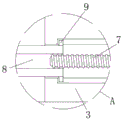
FIG. 1 is a schematic sectional view of the front view of the structure of the present invention;
FIG. 2 is a schematic top view of the structure of the present invention;
FIG. 3 is a schematic top view of the lower injection mold and the fixing column structure of the present invention;
fig. 4 is an enlarged schematic view of a structure in fig. 1 according to the present invention.
In the figure: 1. a lower injection mold; 2. fixing a column; 3. an upper injection mold; 4. a first rotating lever; 5. a first bevel gear; 6. a second bevel gear; 7. a second rotating rod; 8. moving the cutting plate; 9. a slider; 10. a fixing frame; 11. a third rotating rod; 12. a baffle plate; 13. a slider; 14. a hinged lever; 15. a fixed block; 16. a telescopic rod; 17. a top plate.
The specific implementation mode is as follows:
the technical solutions in the embodiments of the present invention will be described clearly and completely with reference to the accompanying drawings in the embodiments of the present invention, and it is obvious that the described embodiments are only some embodiments of the present invention, not all embodiments. Based on the embodiments in the present invention, all other embodiments obtained by a person skilled in the art without creative work belong to the protection scope of the present invention.
Referring to fig. 1-4, the present invention provides an embodiment: the utility model provides a novel combined injection mold, including injection mold 1 and last injection mold 3 down, the top fixedly connected with fixed column 2 of injection mold 1 down, and fixed column 2 keeps away from the one end of injection mold 1 down and inserts the inside of establishing at last injection mold 3, first bull stick 4 is installed through the bearing in the inside of last injection mold 3, and first bull stick 4 inserts the first conical gear 5 of the inside one end fixedly connected with of establishing at last injection mold 3, the surface of first conical gear 5 is inconsistent with the surface of second conical gear 6, and second conical gear 6 keeps away from one side fixedly connected with second bull stick 7 of first conical gear 5, the surface of second bull stick 7 is inconsistent with the inner wall that removes cutting plate 8, and the fixed surface that removes cutting plate 8 is connected with slider 9.
The bottom end of the lower injection mold 1 is fixedly connected with a fixed frame 10, a third rotating rod 11 is mounted inside the fixed frame 10 through a bearing, a baffle 12 is sleeved on the surface of the third rotating rod 11, the surface of the baffle 12 is abutted to the inner wall of a sliding block 13, a hinge rod 14 is hinged on the surface of the sliding block 13, a fixed block 15 is hinged on one end, away from the sliding block 13, of the hinge rod 14, a telescopic rod 16 is fixedly connected on the surface of the fixed block 15, and a top plate 17 is fixedly connected on one end, away from the fixed block 15, of the telescopic rod 16;
furthermore, a circular through hole is formed in the bottom end of the lower injection mold 1, the telescopic rod 16 is cylindrical, the size of the inner wall of the circular through hole formed in the bottom end of the lower injection mold 1 is larger than the surface size of the telescopic rod 16, and the telescopic rod 16 stretches in the circular through hole formed in the bottom end of the lower injection mold 1, so that the top plate 17 can move in the lower injection mold 1, and the demolding of the forming mold is facilitated;
furthermore, the fixing column 2 is cylindrical, a circular groove is formed in the bottom end of the upper injection mold 3, the surface size of the fixing column 2 is smaller than the size of the inner wall of the circular groove formed in the bottom end of the upper injection mold 3, and the fixing column 2 can be inserted into the upper injection mold 3 through the circular groove formed in the bottom end of the upper injection mold, so that the guiding effect is achieved, and the upper injection mold 3 can be conveniently clamped at the top end of the lower injection mold 1;
furthermore, a sliding groove is formed in the upper injection mold 3, the sliding groove formed in the upper injection mold 3 is in sliding connection with the sliding block 9, and the sliding block 9 slides in the sliding groove formed in the upper injection mold 3, so that the cutting plate 8 can be limited and moved;
furthermore, the surface of the second rotating rod 7 is provided with external threads, the inner wall of the movable cutting plate 8 is provided with internal threads, the external threads arranged on the surface of the second rotating rod 7 and the internal threads arranged on the inner wall of the movable cutting plate 8 form threaded connection, and the movable cutting plate 8 can move on the surface of the movable cutting plate through the rotation of the second rotating rod 7, so that the cutting of the pouring gate can be facilitated;
further, the surface of third bull stick 11 is provided with the external screw thread, and the through-hole has been seted up to the inside of sliding block 13, and the inner wall of through-hole is provided with the internal thread, and the external screw thread that the 11 surfaces of third bull stick set up constitutes threaded connection with the internal thread that the through-hole inner wall set up, through the external screw thread that 11 surfaces of third bull stick set up, can make two sets of sliding blocks 13 at its surface relative movement when third bull stick 11 rotates, be convenient for drive hinge rod 14 and remove.
The working principle is as follows: when the lower injection mold 1 is used, according to fig. 1, fig. 2 and fig. 4, after injection of injection liquid is completed, the first rotating rod 4 is rotated to drive the first bevel gear 5 to rotate, and when the first bevel gear 5 rotates, the second bevel gear 6 can be driven to rotate, so that the second bevel gear 6 drives the second rotating rod 7 to rotate, the movable cutting plates 8 can move on the surface of the second rotating rod 7, and when the two groups of movable cutting plates 8 are mutually abutted, the sprue gate can be cut.
When the mould is after the shaping, according to fig. 1 and fig. 3, through rotating third bull stick 11, can make two sets of sliding blocks 13 at its surface relative movement, when sliding block 13 is when removing, can drive hinge bar 14 and remove, through hinge bar 14's removal, can make fixed block 15 remove, when fixed block 15 is when removing, can drive telescopic link 16 and stretch out and draw back in injection mold 1's inside down, thereby can make roof 17 remove in injection mold 1's inside under, the removal through roof 17 can be ejecting with fashioned mould, make things convenient for operating personnel to demold, do above the utility model discloses a whole theory of operation.
It is obvious to a person skilled in the art that the invention is not restricted to details of the above-described exemplary embodiments, but that it can be implemented in other specific forms without departing from the spirit or essential characteristics of the invention. The present embodiments are therefore to be considered in all respects as illustrative and not restrictive, the scope of the invention being indicated by the appended claims rather than by the foregoing description, and all changes which come within the meaning and range of equivalency of the claims are therefore intended to be embraced therein. Any reference sign in a claim should not be construed as limiting the claim concerned.
Claims (6)
1. The utility model provides a novel combined injection mold, includes injection mold (1) and last injection mold (3) down, its characterized in that: the top end of the lower injection mold (1) is fixedly connected with a fixed column (2), one end, far away from the lower injection mold (1), of the fixed column (2) is inserted into the upper injection mold (3), a first rotating rod (4) is installed inside the upper injection mold (3) through a bearing, one end, far away from the lower injection mold (1), of the first rotating rod (4) is fixedly connected with a first bevel gear (5), the surface of the first bevel gear (5) is abutted against the surface of a second bevel gear (6), one side, far away from the first bevel gear (5), of the second bevel gear (6) is fixedly connected with a second rotating rod (7), the surface of the second rotating rod (7) is abutted against the inner wall of a movable cutting plate (8), the surface of the movable cutting plate (8) is fixedly connected with a sliding block (9), and the bottom end of the lower injection mold (1) is fixedly connected with a fixed frame (10), and the inside of fixed frame (10) installs third bull stick (11) through the bearing to baffle (12) have been cup jointed on the surface of third bull stick (11), the surface of baffle (12) is inconsistent with the inner wall of sliding block (13), and the surface of sliding block (13) articulates there is hinge bar (14), the one end that sliding block (13) were kept away from in hinge bar (14) articulates there is fixed block (15), and the fixed surface of fixed block (15) is connected with telescopic link (16), and telescopic link (16) keep away from one end fixedly connected with roof (17) of fixed block (15).
2. A novel modular injection mold as set forth in claim 1, wherein: a circular through hole is formed in the bottom end of the lower injection mold (1), the telescopic rod (16) is cylindrical, and the size of the inner wall of the circular through hole formed in the inner wall of the bottom end of the lower injection mold (1) is larger than the surface size of the telescopic rod (16).
3. A novel modular injection mold as set forth in claim 1, wherein: the fixing column (2) is cylindrical, a circular groove is formed in the bottom end of the upper injection mold (3), and the surface size of the fixing column (2) is smaller than the size of the inner wall of the circular groove formed in the bottom end of the upper injection mold (3).
4. A novel modular injection mold as set forth in claim 1, wherein: a sliding groove is formed in the upper injection mold (3), and the sliding groove formed in the upper injection mold (3) is in sliding connection with the sliding block (9).
5. A novel modular injection mold as set forth in claim 1, wherein: the surface of second bull stick (7) is provided with the external screw thread, the inner wall that removes cutting plate (8) is provided with the internal thread, the external screw thread that second bull stick (7) surface set up constitutes threaded connection with the internal thread that removes cutting plate (8) inner wall and sets up.
6. A novel modular injection mold as set forth in claim 1, wherein: the surface of third bull stick (11) is provided with the external screw thread, the through-hole has been seted up to the inside of sliding block (13), and the inner wall of through-hole is provided with the internal thread, the external screw thread that third bull stick (11) surface set up constitutes threaded connection with the internal thread that the through-hole inner wall set up.
Priority Applications (1)
| Application Number | Priority Date | Filing Date | Title |
|---|---|---|---|
| CN202021122501.4U CN212603094U (en) | 2020-06-17 | 2020-06-17 | Novel combined injection mold |
Applications Claiming Priority (1)
| Application Number | Priority Date | Filing Date | Title |
|---|---|---|---|
| CN202021122501.4U CN212603094U (en) | 2020-06-17 | 2020-06-17 | Novel combined injection mold |
Publications (1)
| Publication Number | Publication Date |
|---|---|
| CN212603094U true CN212603094U (en) | 2021-02-26 |
Family
ID=74717851
Family Applications (1)
| Application Number | Title | Priority Date | Filing Date |
|---|---|---|---|
| CN202021122501.4U Active CN212603094U (en) | 2020-06-17 | 2020-06-17 | Novel combined injection mold |
Country Status (1)
| Country | Link |
|---|---|
| CN (1) | CN212603094U (en) |
-
2020
- 2020-06-17 CN CN202021122501.4U patent/CN212603094U/en active Active
Similar Documents
| Publication | Publication Date | Title |
|---|---|---|
| CN210552855U (en) | Cooling forming device of mould | |
| CN113172826B (en) | Integrated injection mold | |
| CN212603094U (en) | Novel combined injection mold | |
| CN215661651U (en) | Injection mold for liquid containing barrel of automobile | |
| CN208133455U (en) | A kind of injection mold | |
| CN215703595U (en) | Demoulding device for plastic mould | |
| CN213137685U (en) | Injection mold of door handle | |
| CN213500437U (en) | Injection molding machine injection molding device | |
| CN214000319U (en) | Quick-replaceable injection mold for processing high-strength plastic bottles | |
| CN211616411U (en) | Automobile part injection mold | |
| CN113619031A (en) | Plastic mold capable of cutting off excess materials and screening out defective products | |
| CN217021320U (en) | Ejection device for mold processing | |
| CN220075453U (en) | Demolding device for plastic mold | |
| CN215151326U (en) | Full-automatic demoulding precision plastic mould for motor worm | |
| CN214214648U (en) | Multifunctional injection-molded beer set | |
| CN213288655U (en) | Metal product mold ejection device | |
| CN215619659U (en) | Injection mold front mold first demolding mechanism and injection mold | |
| CN218749105U (en) | Automatic change injection moulding's mould | |
| CN214000437U (en) | Automatic plastic part injection mold of drawing of patterns | |
| CN211165143U (en) | Make things convenient for sweeps recovery processing's injection mold | |
| CN218700882U (en) | Flip-chip drawing of patterns injection mold structure | |
| CN211709944U (en) | Injection mold ejection mechanism | |
| CN217319146U (en) | Demoulding device of injection mould | |
| CN219236267U (en) | Mould convenient for demoulding | |
| CN217597698U (en) | Injection mold |
Legal Events
| Date | Code | Title | Description |
|---|---|---|---|
| GR01 | Patent grant | ||
| GR01 | Patent grant |