CN114888565A - Full-automatic ferrule equipment of miniature sealing washer - Google Patents
Full-automatic ferrule equipment of miniature sealing washer Download PDFInfo
- Publication number
- CN114888565A CN114888565A CN202210592714.0A CN202210592714A CN114888565A CN 114888565 A CN114888565 A CN 114888565A CN 202210592714 A CN202210592714 A CN 202210592714A CN 114888565 A CN114888565 A CN 114888565A
- Authority
- CN
- China
- Prior art keywords
- fixedly connected
- assembly
- clamping
- telescopic
- valve rod
- Prior art date
- Legal status (The legal status is an assumption and is not a legal conclusion. Google has not performed a legal analysis and makes no representation as to the accuracy of the status listed.)
- Granted
Links
Images


Classifications
-
- B—PERFORMING OPERATIONS; TRANSPORTING
- B23—MACHINE TOOLS; METAL-WORKING NOT OTHERWISE PROVIDED FOR
- B23P—METAL-WORKING NOT OTHERWISE PROVIDED FOR; COMBINED OPERATIONS; UNIVERSAL MACHINE TOOLS
- B23P21/00—Machines for assembling a multiplicity of different parts to compose units, with or without preceding or subsequent working of such parts, e.g. with programme control
- B23P21/004—Machines for assembling a multiplicity of different parts to compose units, with or without preceding or subsequent working of such parts, e.g. with programme control the units passing two or more work-stations whilst being composed
- B23P21/006—Machines for assembling a multiplicity of different parts to compose units, with or without preceding or subsequent working of such parts, e.g. with programme control the units passing two or more work-stations whilst being composed the conveying means comprising a rotating table
-
- B—PERFORMING OPERATIONS; TRANSPORTING
- B07—SEPARATING SOLIDS FROM SOLIDS; SORTING
- B07C—POSTAL SORTING; SORTING INDIVIDUAL ARTICLES, OR BULK MATERIAL FIT TO BE SORTED PIECE-MEAL, e.g. BY PICKING
- B07C5/00—Sorting according to a characteristic or feature of the articles or material being sorted, e.g. by control effected by devices which detect or measure such characteristic or feature; Sorting by manually actuated devices, e.g. switches
- B07C5/34—Sorting according to other particular properties
-
- B—PERFORMING OPERATIONS; TRANSPORTING
- B23—MACHINE TOOLS; METAL-WORKING NOT OTHERWISE PROVIDED FOR
- B23P—METAL-WORKING NOT OTHERWISE PROVIDED FOR; COMBINED OPERATIONS; UNIVERSAL MACHINE TOOLS
- B23P19/00—Machines for simply fitting together or separating metal parts or objects, or metal and non-metal parts, whether or not involving some deformation; Tools or devices therefor so far as not provided for in other classes
- B23P19/001—Article feeders for assembling machines
Abstract
The embodiment of the application provides full-automatic ring equipment of miniature sealing washer, relates to precision seal ring assembly technical field. A full-automatic micro-seal ring sleeving device comprises: the fifth extensible member is fixed on the fourth extensible member, the second clamping member is fixed on the fifth extensible member, the sixth extensible member is fixed on the fourth extensible member, the third clamping member is fixed on the sixth extensible member, the vacuum chuck is respectively arranged on the second clamping member and the third clamping member, the material supplementing assembly is arranged on the base, the material cutting assembly is arranged on one side of the material supplementing assembly, the material receiving mechanism is arranged on the base, the detection mechanism is fixed on the base, and the turnover mechanism is fixed on the base.
Description
Technical Field
The application relates to the technical field of precision seal ring assembly, in particular to full-automatic ring-sleeving equipment for a micro seal ring.
Background
The valve rod is an important part of the valve and is used for transmission, an actuating mechanism or a handle is connected to the valve rod, and the valve core is directly driven to move or rotate under the actuating mechanism or the handle so as to realize the opening and closing or adjusting functions of the valve.
In the operation process of establishing accurate sealing washer at current valve rod cover, often adopt the manual work to carry out the lasso for the work efficiency of lasso very reduces, and often because staff's carelessness is careless, can lead to the phenomenon of leaking the cover to appear in the valve rod.
Disclosure of Invention
The present application is directed to solving at least one of the problems in the prior art. To this end, the application provides a full-automatic ferrule device for a micro seal ring, which utilizes a feeding mechanism to realize the feeding operation of the seal ring, utilizes a fourth telescopic part to change the transverse positions of a second clamping part and a third clamping part, utilizes a fifth telescopic part and a sixth telescopic part to respectively change the vertical positions of the second clamping part and the third clamping part, utilizes a vacuum chuck to suck and put down the micro seal ring, the position change of the clamping parts is matched with the suction and the putting down of the vacuum chuck to realize the position change of the seal ring, positions the position of a valve rod through a second positioning assembly, and is matched with a bearing disc driven by a power part to rotate to realize the automatic ferrule operation of the seal ring, and utilizes a receiving mechanism to collect the valve rod which completes the ferrule action, and the design realizes the automation of the whole ferrule process, the labor intensity of workers is reduced, the working efficiency is improved, and meanwhile, the sleeve leakage phenomenon caused by manual operation is avoided as much as possible.
The application provides a full-automatic lasso equipment of miniature sealing washer, includes: the supporting mechanism comprises a base, a bearing disc and a power piece, the bearing disc is connected to the output end of the power piece in a transmission mode, and one end, far away from the bearing disc, of the power piece is fixedly connected to the base; the feeding mechanism is arranged on the base; the ferrule mechanism comprises a ferrule assembly, a second positioning assembly, a material supplementing assembly and a material cutting assembly, the ferrule assembly comprises a third support, a fourth telescopic piece, a fifth telescopic piece, a second clamping piece, a sixth telescopic piece, a third clamping piece and a vacuum chuck, the third support is fixedly connected to the base, the fourth telescopic piece is fixedly connected to the third support, the fifth telescopic piece is fixedly connected to the output end of the fourth telescopic piece, the second clamping piece is fixedly connected to the output end of the fifth telescopic piece, the sixth telescopic piece is fixedly connected to the output end of the fourth telescopic piece, the third clamping piece is fixedly connected to the output end of the sixth telescopic piece, the vacuum chuck is respectively arranged on the second clamping piece and the third clamping piece, the second positioning assembly is fixedly connected to the supporting mechanism, and the material supplementing assembly is arranged on the base, the cutting assembly is arranged on one side of the feeding assembly; the material receiving mechanism is arranged on the base; the detection mechanism is fixedly connected to the base and is used for detecting a sealing ring on the valve rod; the turnover mechanism is fixedly connected to the base and used for controlling the valve rod to turn over.
In addition, the fully automatic ring-sleeving equipment for the micro sealing ring according to the embodiment of the application also has the following additional technical characteristics:
in some embodiments of the present application, a control unit is disposed in the base, and the control unit performs a predetermined program operation on the electrical equipment in the micro-sealing ring full-automatic ring-sealing equipment.
In some embodiments of the present application, the feeding mechanism includes a feeding assembly, a clamping assembly and a first positioning assembly, one end of the feeding assembly is fixedly connected to the base, the other end of the feeding assembly is obliquely disposed on the bottom side of the clamping assembly, the clamping assembly is fixedly connected to the base, a part of the first positioning assembly is fixedly connected to the carrying tray, and another part of the first positioning assembly is fixedly connected to the base.
In some embodiments of the present application, a telescopic direction of the fourth telescopic member is perpendicular to a height direction of the third support, a telescopic direction of the fifth telescopic member is perpendicular to a telescopic direction of the fourth telescopic member, and a telescopic direction of the sixth telescopic member is identical to a telescopic direction of the fifth telescopic member.
In some embodiments of the present application, the second positioning assembly includes a second lifting member, a second clamping seat, a second lifting block, a second connecting rod and a second clamping block, the second lifting member is fixedly connected to the base, the second clamping seat is fixedly connected to the bearing plate, the second lifting block is slidably connected to the second clamping seat, one end of the second connecting rod is hinged to the second lifting block, the other end of the second connecting rod is hinged to the second clamping block, and the second clamping block is slidably connected to the second clamping seat.
In some embodiments of the present application, the second positioning assembly and the first positioning assembly are identical in structural size.
In some embodiments of the present application, the second clamping seat top end is provided with a through hole, and the diameter of the through hole of the second clamping seat top end is not smaller than the diameter of the valve rod.
In some embodiments of this application, the feed supplement subassembly contains protecting crust, driving piece, carousel, spacing dish and unloading pipe, protecting crust fixed connection in supporting mechanism, driving piece fixed connection in the protecting crust, the carousel transmission connect in the output of driving piece, the clamp that carousel week side fixedly connected with circumference array set up, spacing dish fixed connection in the protecting crust, be provided with the through-hole on the spacing dish, the output of driving piece rotates and runs through spacing dish, unloading pipe joint in on carousel week side fixed connection's the clamp, the unloading pipe with the through-hole cooperation that sets up on the spacing dish.
In some embodiments of the present application, the cutting assembly comprises a cutting disc, a gear, a rack, a second expansion member, a second bracket, a third expansion member and a positioning rod, the cutting disc is provided with a recess, the recess provided on the cutting disc cooperates with a through hole provided on the limiting disc, the cutting disc is rotatably connected to the second bracket, the cutting disc is fixedly connected with the gear, the gear is engaged with the rack, the rack is slidably connected to the second bracket, the second expansion member is fixedly connected to the second bracket, an output end of the second expansion member is fixedly connected to the rack, the second bracket is fixedly connected to the supporting mechanism, the third expansion member is fixedly connected to one side of the second bracket far away from the second expansion member, the output end of the third expansion member is provided with the positioning rod, the top end of the positioning rod is designed to be conical.
In some embodiments of the present application, the material receiving mechanism includes a fifth positioning assembly, a material receiving assembly, a conveying assembly, and a push-pull assembly, the fifth positioning assembly is disposed on the supporting mechanism, the fifth positioning assembly and the second positioning assembly have the same structure and size, the material receiving assembly is fixedly connected to the base, the conveying assembly is fixedly connected to the base, one end of the push-pull assembly is fixedly connected to the base, and the other end of the push-pull assembly is fixedly connected to the bottom of the material receiving assembly.
In some embodiments of this application, detection mechanism contains third locating component and determine module, third locating component fixed connection in on the supporting mechanism, third locating component with second locating component's structure size is the same completely, determine module contains branch, fixture block and laser sensor, branch fixed connection in the base, the fixture block set up in the branch top, laser sensor joint in on the fixture block.
In some embodiments of the present application, the turnover mechanism includes a lifting assembly, a turnover assembly, and a fourth positioning assembly, the lifting assembly includes a third bracket and a seventh telescopic member, the third bracket is fixedly connected to the base, the seventh telescopic member is fixedly connected to the third bracket, the turnover assembly includes a turnover member, a fourth clamping member, and a limiting member, the turnover member is fixedly connected to an output end of the seventh telescopic member, the fourth clamping member is fixedly connected to the turnover member, the limiting member is fixedly connected to the fourth clamping member, the fourth positioning assembly includes a fourth lifting member, a fourth clamping seat, a fourth lifting block, a fourth connecting rod, and a fourth clamping block, the fourth lifting member is fixedly connected to the supporting mechanism, the fourth clamping seat is fixedly connected to the supporting mechanism, and the fourth lifting block is slidably connected to the fourth clamping seat, one end of the fourth connecting rod is hinged to the fourth lifting block, the other end of the fourth connecting rod is hinged to the fourth clamping block, the fourth connecting rod is symmetrically designed, and the fourth clamping block is connected to the fourth clamping seat in a sliding mode.
According to the full-automatic ring sleeving equipment for the micro sealing ring, the feeding operation of the sealing ring is realized by using the feeding mechanism, the transverse positions of the second clamping piece and the third clamping piece are changed by using the fourth telescopic piece, the vertical positions of the second clamping piece and the third clamping piece are respectively changed by using the fifth telescopic piece and the sixth telescopic piece, the micro sealing ring is sucked and put down by using the vacuum chuck, the position change of the clamping piece is matched with the sucking and putting down of the vacuum chuck to realize the position change of the sealing ring, the position of the valve rod is positioned by the second positioning assembly, the automatic ring sleeving operation of the sealing ring is realized by matching with the bearing plate which is driven by the power piece to rotate, and the valve rod which completes the ring sleeving action is collected by using the material collecting mechanism, so that the whole ring sleeving process is automated, the labor intensity of workers is reduced, and the working efficiency is improved, meanwhile, the sleeve leakage phenomenon caused by manual operation is avoided as much as possible.
Additional aspects and advantages of the present application will be set forth in part in the description which follows and, in part, will be obvious from the description, or may be learned by practice of the present application.
Drawings
In order to more clearly illustrate the technical solutions of the embodiments of the present application, the drawings that are required to be used in the embodiments of the present application will be briefly described below, it should be understood that the following drawings only illustrate some embodiments of the present application and therefore should not be considered as limiting the scope, and that those skilled in the art can also obtain other related drawings based on the drawings without inventive efforts.
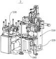
FIG. 1 is a diagram of the overall structure position of a full-automatic micro-seal ring looping device according to an embodiment of the application;
FIG. 2 is an exploded view of a support mechanism according to an embodiment of the present application;
FIG. 3 is a schematic structural diagram of a feed mechanism according to an embodiment of the present application;
FIG. 4 is a schematic illustration of a partial structure of a feed assembly according to an embodiment of the present application;
FIG. 5 is a schematic illustration of a portion of a first positioning assembly according to an embodiment of the present application;
FIG. 6 is a partial schematic structural view of a ferrule mechanism according to an embodiment of the present application;
FIG. 7 is an exploded view of the structure of a ferrule assembly according to an embodiment of the present application;
FIG. 8 is a schematic structural diagram of a second positioning assembly according to an embodiment of the present application;
FIG. 9 is an exploded view of the structure of a feed assembly according to an embodiment of the present application;
FIG. 10 is an exploded view of the construction of a blanking assembly according to an embodiment of the present application;
FIG. 11 is a schematic diagram of the position and configuration of a detection mechanism according to an embodiment of the present application;
FIG. 12 is a schematic view of a partial structure of a detection mechanism according to an embodiment of the present application;
FIG. 13 is a schematic view of a portion of a canting mechanism according to an embodiment of the present application;
FIG. 14 is an exploded view of the construction of a flip assembly according to an embodiment of the present application;
FIG. 15 is an exploded view of a fourth positioning assembly according to an embodiment of the present application;
FIG. 16 is a schematic structural view of a receiving mechanism according to an embodiment of the present application;
FIG. 17 is a schematic structural diagram of a fifth positioning assembly according to an embodiment of the present application;
FIG. 18 is a schematic view of a partial structure of a receiving assembly according to an embodiment of the present application;
FIG. 19 is an exploded view of a partial structure of a receiving assembly according to an embodiment of the present application;
FIG. 20 is an exploded view of the structure of a transfer assembly according to an embodiment of the present application;
figure 21 is a schematic partial structure view of a push-pull assembly according to an embodiment of the present application.
Icon: 1. a support mechanism; 110. a base; 111. a control unit; 120. a carrier tray; 130. a power member; 2. a feeding mechanism; 210. a feed assembly; 211. a feeding compartment; 212. a distributor; 213. a material guide chute; 214. a divider; 215. a drainage plate; 220. a gripping assembly; 221. a first bracket; 222. an electric push rod; 223. a first telescoping member; 224. a first clamping member; 230. a first positioning assembly; 231. a first lifting member; 232. a first clamping seat; 233. a first lifting block; 234. a first link; 235. a first clamping block; 3. a ferrule mechanism; 310. a ferrule assembly; 311. a third support; 312. a fourth telescoping member; 313. a fifth telescoping member; 314. a second clamping member; 315. a sixth telescoping member; 316. a third clamping member; 317. a vacuum chuck; 320. a second positioning assembly; 321. a second lifting member; 322. a second clamping seat; 323. a second lifting block; 324. a second link; 325. a second clamping block; 330. a feed supplement assembly; 331. a protective shell; 332. a drive member; 333. a turntable; 334. a limiting disc; 335. a discharging pipe; 340. a material cutting assembly; 341. cutting a material plate; 342. a gear; 343. a rack; 344. a second telescoping member; 345. a second bracket; 346. a third telescoping member; 347; positioning a rod; 4. a detection mechanism; 410. a third positioning assembly; 420. a detection component; 421. a strut; 422; a clamping block; 423. a laser sensor; 5. a turnover mechanism; 510. a lifting assembly; 511. a fourth bracket; 512. a seventh telescoping member; 520. a turnover assembly; 521. a turnover piece; 522. a fourth clamping member; 523. a limiting member; 530. a fourth positioning assembly; 531. a fourth lifting member; 532. a fourth clamping seat; 533. a fourth lifting block; 534. a fourth link; 535. a fourth clamping block; 6. a material receiving mechanism; 610. a fifth positioning assembly; 611. a fifth lifting member; 612. a fifth clamping seat; 613. a fifth lifting block; 614. a fifth link; 615. a fifth clamping block; 620. a material receiving assembly; 621. a fifth support; 622. an eighth telescoping member; 623. a rotating member; 624. a fifth clamping member; 625. a slider; 630. a delivery assembly; 631. a sixth support; 632. a conveyor belt; 640. a push-pull assembly; 641. a ninth telescoping member; 642. a limiting rod.
Detailed Description
The technical solutions in the embodiments of the present application will be described below with reference to the drawings in the embodiments of the present application.
To make the objects, technical solutions and advantages of the embodiments of the present application clearer, the technical solutions of the embodiments of the present application will be clearly and completely described below with reference to the drawings in the embodiments of the present application, and it is obvious that the described embodiments are some embodiments of the present application, but not all embodiments. All other embodiments obtained by a person of ordinary skill in the art without any inventive work based on the embodiments in the present application are within the scope of protection of the present application.
The following describes a full-automatic micro-seal ring looping device according to an embodiment of the application with reference to the attached drawings.
As shown in fig. 1 to 21, a full-automatic micro-seal ring ferrule apparatus according to an embodiment of the present application includes: the device comprises a supporting mechanism 1, a feeding mechanism 2, a ring sleeving mechanism 3, a detection mechanism 4, a turnover mechanism 5 and a material receiving mechanism 6.
The feeding mechanism 2 is arranged on the supporting mechanism 1, the ferrule mechanism 3 is arranged on the supporting mechanism 1, the detection mechanism 4 is arranged on the supporting mechanism 1, the turnover mechanism 5 is arranged on the supporting mechanism 1, the receiving mechanism 6 is arranged on the supporting mechanism 1, the feeding mechanism 2 supplies valve rods to the ferrule mechanism 3, the ferrule mechanism 3 automatically assembles the valve rods, the receiving mechanism 6 collects the valve rods which finish ferrule movement, wherein, the detection mechanism 4 is arranged at different positions to detect the valve rods at different positions, so as to avoid the situation that the assembly position of the sealing ring on the valve rod does not reach the standard and whether the valve rod after the ferrule action is completed on the supporting mechanism 1 is completely taken out, the turnover mechanism 5 carries out the position-changing operation of two ends on the valve rod which completes the ferrule action for the first time, so that the valve rod can complete the ferrule movement at two ends on the micro-sealing ring full-automatic ferrule device.
According to some embodiments of the present application, as shown in fig. 1 to 21, the supporting mechanism 1 includes a base 110, a carrying tray 120 and a power component 130, the carrying tray 120 is connected to an output end of the power component 130 in a transmission manner, so that the carrying tray 120 can be driven by the power component 130 to rotate, one end of the power component 130 far away from the carrying tray 120 is fixedly connected to the base 110, a control unit 111 is disposed in the base 110, and the control unit 111 performs a predetermined program operation on an electrical device in the micro sealing ring full-automatic ring-looping device, thereby achieving an automatic operation.
The feeding mechanism 2 comprises a feeding assembly 210, a clamping assembly 220 and a first positioning assembly 230, wherein one end of the feeding assembly 210 is fixedly connected to the base 110, the other end of the feeding assembly 210 is obliquely arranged at the bottom side of the clamping assembly 220 to facilitate feeding of the valve rod, the clamping assembly 220 is fixedly connected to the base 110, a part of the first positioning assembly 230 is fixedly connected to the bearing plate 120, the other part of the first positioning assembly 230 is fixedly connected to the base 110, and the first positioning assembly 230 vertically corresponds to the base 110 and the bearing plate 120.
Wherein, the feeding assembly 210 comprises a feeding cabin 211, a distributor 212, a material guiding groove 213 and a divider 214, the feeding cabin 211 is fixedly connected to the base 110, the distributor 212 is fixedly connected to the feeding cabin 211, the material guiding groove 213 is fixedly connected to the feeding cabin 211, the divider 214 is fixedly connected to the material guiding groove 213, a flow guiding plate 215 is fixedly connected to the inside of the feeding cabin 211, the flow guiding plate 215 is obliquely arranged to facilitate blanking, an output end of the distributor 212 is positioned at the lowest end of the flow guiding plate 215 to facilitate ejecting the valve stem out of the feeding cabin 211, the material guiding groove 213 is obliquely arranged, one end of the material guiding groove 213 close to the feeding cabin 211 is higher than one end of the material guiding groove 213 close to the divider 214 to facilitate the valve stem sliding towards the divider 214, the clamping assembly 220 comprises a first bracket 221, an electric push rod 222, a first telescopic member 223 and a first clamping member 224, the first bracket 221 is fixedly connected to the base 110, the electric push rod 222 is fixedly connected to the first bracket 221, the fixed one of first extensible member 223 is connected in electric putter 222's output, first holder 224 is fixed connection in first extensible member 223's output, electric putter 222 transversely fixed connection is in first support 221, the flexible direction of first extensible member 223 and electric putter 222's flexible direction are perpendicular, be convenient for control first holder 224 horizontal and vertical concrete position on first support 221, the completion shifts the position of valve rod, first locating component 230 is located the discharge end of feeding component 210, first elevator 233 is located the top of first lift 231 output.
The ferrule mechanism 3 comprises a ferrule assembly 310, a second positioning assembly 320, a feeding assembly 330 and a cutting assembly 340, wherein the ferrule assembly 310 comprises a third support 311, a fourth telescopic member 312, a fifth telescopic member 313, a second clamping member 314, a sixth telescopic member 315, a third clamping member 316 and a vacuum chuck 317, the third support 311 is fixedly connected to the base 110, the fourth telescopic member 312 is fixedly connected to the third support 311, the fifth telescopic member 313 is fixedly connected to the output end of the fourth telescopic member 312, the second clamping member 314 is fixedly connected to the output end of the fifth telescopic member 313, the sixth telescopic member 315 is fixedly connected to the output end of the fourth telescopic member 312, the third clamping member 316 is fixedly connected to the output end of the sixth telescopic member 315, the vacuum chucks 317 are respectively arranged on the second clamping member 314 and the third clamping member 316, the second positioning assembly 320 is fixedly connected to the supporting mechanism 1, the feeding assembly 330 is arranged on the base 110, the blanking assembly 340 is arranged on one side of the feeding assembly 330, the extending direction of the fourth expansion piece 312 is perpendicular to the height direction of the third support 311, the extending direction of the fifth expansion piece 313 is perpendicular to the extending direction of the fourth expansion piece 312, the extending direction of the sixth expansion piece 315 is the same as the extending direction of the fifth expansion piece 313, so that the fourth expansion piece 312 can simultaneously control the transverse positions of the fifth expansion piece 313 and the sixth expansion piece 315 on the third support 311, the fifth expansion piece 313 and the sixth expansion piece 315 can control the vertical positions of the two vacuum chucks 317 on the third support 311, the second positioning assembly 320 comprises a second lifting piece 321, a second clamping seat 322, a second lifting block 323, a second connecting rod 324 and a second clamping block 325, the second lifting piece 321 is fixedly connected to the base 110, the second clamping seat 322 is fixedly connected to the carrier plate 120, and the second lifting block 323 is slidably connected to the second clamping seat 322, one end of a second connecting rod 324 is hinged to the second lifting block 323, the other end of the second connecting rod 324 is hinged to a second clamping block 325, the second clamping block 325 is connected to a second clamping seat 322 in a sliding manner, so that the position of the second lifting member 321 is fixed, the second clamping seat 322, the second lifting block 323, the second connecting rod 324 and the second clamping block 325 rotate along with the bearing disc 120, so as to change the position of the valve rod and perform operations of different steps, the second positioning assembly 320 and the first positioning assembly 230 have the same structural size, the top end of the second clamping seat 322 is provided with a through hole, the diameter of the through hole at the top end of the second clamping seat 322 is not smaller than the diameter of the valve rod, so as to perform alignment positioning and clamping on the valve rod, the feeding assembly 330 comprises a protective shell 331, a driving member 334, a rotary disc 333, a limiting disc and a blanking tube 335, the protective shell 331 is fixedly connected to the supporting mechanism 1, the driving member 332 is fixedly connected to the protective shell 331, the rotary table 333 is in transmission connection with the output end of the driving part 332, the periphery of the rotary table 333 is fixedly connected with hoops arranged in a circumferential array, the limiting disc 334 is fixedly connected with the protective shell 331, through holes are formed in the limiting disc 334 to facilitate the passing of a sealing ring, the output end of the driving part 332 rotates to penetrate through the limiting disc 334, so that the driving part 332 does not interfere with the limiting disc 334 when driving the rotary table 333 to rotate, the blanking pipe 335 is clamped on the hoops fixedly connected with the periphery of the rotary table 333, the blanking pipe 335 is matched with the through holes formed in the limiting disc 334 to facilitate the falling of the sealing ring in the blanking pipe 335, the blanking assembly 340 comprises a blanking disc 341, a gear 342, a rack 343, a second telescopic part 344, a second bracket 345, a third telescopic part 346 and a positioning rod 347, a recess is formed in the blanking disc 341, the recess formed in the blanking disc 334 is matched with the through holes formed in the limiting disc to facilitate the storage of the sealing ring, the blanking disc 341 is rotatably connected with the second bracket 345, the gear 342 is fixedly connected to the cutting disc 341, the gear 342 is engaged with the rack 343, the rack 343 is slidably connected to the second bracket 345, the second telescopic member 344 is fixedly connected to the second bracket 345, the output end of the second telescopic member 344 is fixedly connected to the rack 343, so that the second telescopic member 344 can control the lateral position of the rack 343 on the second bracket 345 by means of the telescopic movement, and then the gear 342 is driven to rotate by means of the rack 343, so that the cutting disc 341 changes its angle on the second bracket 345 to complete the transfer of the sealing ring, the second bracket 345 is fixedly connected to the supporting mechanism 1, the third telescopic member 346 is fixedly connected to the side of the second bracket 345 far away from the second telescopic member 344, the output end of the third telescopic member 346 is provided with a positioning rod 347, the vertical position of the positioning rod 347 can be changed by the extension of the third telescopic piece 346, and the top end of the positioning rod 347 is in a conical design, so that a sealing ring can be conveniently placed.
The receiving mechanism 6 comprises a fifth positioning component 610, a receiving component 620, a conveying component 630 and a push-pull component 640, the fifth positioning component 610 is arranged on the supporting mechanism 1, the structure sizes of the fifth positioning component 610 and the second positioning component 320 are identical, the receiving component 620 is fixedly connected to the base 110, the conveying component 630 is fixedly connected to the base 110, the valve rod which is assembled with the sealing ring is collected, one end of the push-pull component 640 is fixedly connected to the base 110, the other end of the push-pull component 640 is fixedly connected to the bottom of the receiving component 620, the receiving component 620 is used for displacing the valve rod which is assembled and the valve rod which is not assembled are collected separately.
Wherein, the fifth positioning assembly 610 comprises a fifth lifting piece 611, a fifth clamping seat 612, a fifth lifting block 613, a fifth connecting rod 614 and a fifth clamping block 615, the fifth lifting piece 611 is fixedly connected to the supporting mechanism 1, the fifth clamping seat 612 is fixedly connected to the supporting mechanism 1, the fifth lifting block 613 is slidably connected to the fifth clamping seat 612, one end of the fifth connecting rod 614 is hinged to the fifth lifting block 613, the other end of the fifth connecting rod 614 is hinged to the fifth clamping block 615, the fifth clamping block 615 is slidably connected to the fifth clamping seat 612, the output end of the fifth lifting piece 611 is located at the bottom side of the fifth lifting block 613, the fifth connecting rod 614 is symmetrically arranged so as to enable the fifth lifting piece 611 to realize the clamping and releasing actions of the fifth clamping block 615 through telescopic change, the material receiving assembly 620 comprises a fifth bracket 621, an eighth telescopic piece 622, a rotating piece 623, a fifth clamping piece 624 and a sliding piece 625, the fifth support 621 is fixedly connected to the support mechanism 1, the eighth expansion element 622 is fixedly connected to the fifth support 621, the rotating element 623 is fixedly connected to the expansion end of the eighth expansion element 622, the fifth clamping element 624 is fixedly connected to one side of the rotating element 623 far away from the eighth expansion element 622, one end of the sliding element 625 is fixedly connected to the support mechanism 1, the other end of the sliding element 625 is fixedly connected to the fifth support 621, the conveying assembly 630 is fixedly connected to the support mechanism 1, one end of the push-pull assembly 640 is fixedly connected to the support mechanism 1, and the output end of the push-pull assembly 640 is fixedly connected to the fifth support 621. The extending and retracting direction of the eighth telescopic element 622 is consistent with the height direction of the fifth support 621, so as to change the height positions of the rotating element 623 and the fifth clamping element 624, the clamping point of the fifth clamping element 624 is coaxial with the clamping point of the fifth clamping block 615, so as to clamp and take the valve rod, the conveying assembly 630 comprises a sixth support 631 and a conveyor belt 632, the sixth support 631 is fixedly connected to the supporting mechanism 1, the conveyor belt 632 is arranged on the sixth support 631, one end of the conveyor belt 632 is arranged on one side of the receiving assembly 620, the other end of the conveyor belt 632 is provided with a receiving box, so as to store the valve rod with the completed ferrule, the push-pull assembly 640 comprises a ninth telescopic element 641 and a limit rod 642, one end of the ninth telescopic element 641 is fixedly connected to the supporting mechanism 1, the output end of the ninth telescopic element 641 is fixedly connected to the fifth support 621, so as to control the position of the whole assembly 620, and the limit rod is fixedly connected to the supporting mechanism 1, the limiting rods 642 are symmetrically arranged, the limiting rods 642 are respectively arranged on the fifth support 621, the moving position of the material receiving assembly 620 is convenient to limit, and a defective product box is arranged on one side, away from the ninth telescopic piece 641, of the fifth support 621, so that the valve rod of an unfinished ferrule can be conveniently stored.
It should be noted that, the bottom position of the blanking disc 341 is in clearance fit with the upper surface position of the second bracket 345, the upper surface position of the blanking disc 341 is in clearance fit with the lower surface position of the limiting disc 334, and only one concave part is arranged on the blanking disc 341, so that other sealing rings in the blanking pipe 335 are conveniently blocked in the rotation process of the blanking disc 341, and the sealing rings in the blanking pipe 335 are prevented from falling to other positions.
It should be noted that the second telescopic member 344, the rack 343, and the gear 342 are configured according to the model, parameters, etc. so that the cutting disc 341 can only make 90 ° reciprocating rotation around the rotation connection between itself and the second bracket 345 when the rack 343 moves to drive the gear 342 to rotate.
It should be noted that the initial position of the blanking tray 341 is that the upper recess is located right below the through hole of the limiting tray 334, and after the blanking tray 341 rotates 90 degrees, the upper recess is located right below the vacuum chuck 317 on the second clamping member 314, so that the vacuum chuck 317 can suck the sealing ring on the blanking tray 341.
It can be understood that, in the using process, the valve rod is placed on the obliquely designed flow guide plate 215, the valve rod slides down along the flow guide plate 215 to the output end of the distributor 212, then the distributor 212 ejects the valve rod out of the feeding chamber 211 one by one, the valve rod slides down through the obliquely arranged material guiding groove 213 to the divider 214, then the first clamping member 224 adjusts the specific position of the first clamping member 221 by the electric push rod 222 and the first telescopic member 223, the valve rod on the divider 214 is clamped, then the position is adjusted, the valve rod is placed between the first clamping blocks 235, the first clamping blocks 235 in the initial state are in the separated state, that is, the first lifting member 231 at this time is in the extended state, and after the valve rod is placed between the first clamping blocks 235, the first lifting member 231 contracts and is under the action of self gravity, the first lifting blocks 233 at this time displace downwards on the first clamping seats 232, and then the first connecting rods 234 hinged to the first clamping blocks 232 symmetrically draw the first clamping blocks 235 to approach each other The valve rod is engaged, so that the valve rod is not changed in position and is in a vertical state, the subsequent ferrule operation of the micro sealing ring is conveniently carried out on the valve rod, then the bearing plate 120 rotates clockwise for a set angle, so that the valve rod clamped on the first positioning assembly 230 rotates to the top end of the second lifting part 321, then the bearing plate 120 stops rotating, meanwhile, when in use, the blanking pipe 335 is filled with the sealing ring and then is arranged on the rotating disc 333 through a hoop, the sealing ring in the blanking pipe 335 can fall into the concave part of the cutting plate 341 below the through hole through the corresponding arrangement of the through hole on one of the blanking pipe 335 and the limiting plate 334, then the rack 343 is driven to transversely displace on the second bracket 345 through the telescopic change of the second telescopic part 344, the gear 342 is driven to rotate, and the cutting plate 341 fixedly connected with the gear 342 rotates by taking the rotation joint of the rack and the second bracket 345 as an axis, then the material cutting disc 341 conveys the sealing ring to the lower part of the vacuum chuck 317 on the second clamping member 314, because the bottom end position of the material cutting disc 341 is in clearance fit with the upper surface position of the second bracket 345, the upper surface position of the material cutting disc 341 is in clearance fit with the lower surface position of the limiting disc 334, and only one concave part is arranged on the material cutting disc 341, so that other sealing rings in the blanking pipe 335 are blocked in the rotation process of the material cutting disc 341, the sealing rings in the blanking pipe 335 are prevented from falling to other positions, at this time, the fifth telescopic member 313 and the second clamping member 314 thereon generate transverse displacement relative to the third bracket 311 through the telescopic change of the fourth telescopic member 312, so that the vacuum chuck 317 on the second clamping member 314 is positioned right above the sealing ring on the material cutting disc 341, and the vacuum chuck 317 is close to the sealing ring on the material cutting disc 341 through the telescopic change of the fifth telescopic member 313, the vacuum chuck 317 can suck the sealing ring conveniently, then the fourth expansion part 312 contracts to drive the second clamping part 314 to reset, at the moment, the vacuum chuck 317 on the second clamping part 314 is displaced to be right above the positioning rod 347, then the fifth expansion part 313 extends to enable the vacuum chuck 317 to be sleeved on the positioning rod 347, then the vacuum chuck 317 puts down the sealing ring in the second clamping part, meanwhile, the third expansion part 346 extends to drive the positioning rod 347 to rise, so that the sealing ring can be stably sleeved on the top of the positioning rod 347, in the process, the cutting disc 341 resets after the vacuum chuck 317 sucks the sealing ring on the cutting disc, so that the sealing ring in the discharging pipe 335 can fall to the concave part on the cutting disc 341, then the actions are repeated, the next sealing ring is rotated to the direction of the second clamping part 314 through the cutting disc 341, and the first sleeved sealing ring is behind the top of the positioning rod 347, the fourth expansion piece 312 extends to reset the second clamping piece 314 and the third clamping piece 316, at this time, the vacuum chuck 317 on the second clamping piece 314 is located above the next seal ring, the vacuum chuck 317 on the third clamping piece 316 is located above the positioning rod 347 at this time, the fifth expansion piece 313 and the sixth expansion piece 315 synchronously expand and contract, so that the two vacuum chucks 317 suck the two seal rings simultaneously and then synchronously ascend to facilitate displacement, at this time, the fourth expansion piece 312 contracts to enable the vacuum chuck 317 on the third clamping piece 316 to displace to the positioning rod 347, at this time, the vacuum chuck 317 on the third clamping piece 316 displaces to the position above the valve rod clamped by the second clamping block 325, and then the fifth expansion piece 313 and the sixth expansion piece 315 synchronously expand and contract, so that the two seal rings are completely sleeved on the positioning rod 347, one seal ring is completely sleeved on the valve rod, and the operation of automatic ferrule is completed, after the valve rod on the second clamping block 325 completes the ferrule movement, the control unit 111 controls the power part 130 to start, so that the bearing disc 120 continues to rotate clockwise by a predetermined angle, so that the valve rod completing the ferrule rotates to the next station, and at the same time, the external sensing device monitors the sealing ring in the blanking pipe 335, the external sensing device is in signal connection with the control unit 111, so as to transmit a start-stop signal to the driving part 332, after the sensing device monitors that the sealing ring in the blanking pipe 335 corresponding to the through hole on the limiting disc 334 is used, the driving part 332 is controlled to start through signal transmission, so as to drive the rotating disc 333 to rotate, so that the next blanking pipe 335 clamped on the circumferential side 333 of the rotating disc is displaced to the through hole on the limiting disc 334, so as to realize sustainable sealing ring supply, and when the valve rod is collected, the eighth telescopic part 622 contracts, so that the fifth clamping part 624 clamps the valve rod on the fifth clamping block 615, then the fifth clamping block 615 extends through the fifth lifting piece 611 to change the angle of the fifth connecting rod 614, so that the fifth clamping block 615 releases the valve rod, the eighth telescopic piece 622 extends to enable the fifth clamping piece 624 to take the valve rod out of the fifth clamping block 615, then the rotating piece 623 drives the fifth clamping piece 624 to rotate, the valve rod on the fifth clamping piece 624 is enabled to be released after the valve rod faces the conveying belt 632, the valve rod falls to the conveying belt 632, and the valve rod is conveyed into the collecting box through the conveying belt 632.
In the related art, in the process of looping a valve rod, whether the valve rod has a loop or not, how the loop effect is achieved, and in the whole process, whether the valve rod which is not taken down is on a workpiece on the bearing disc 120 or not is often monitored by naked eyes of a worker, and manual operation is often ineffective due to carelessness of the worker, so that the phenomena of leakage of the loop or unqualified assembly of the sealing ring and the like occur in the whole loop process, and the efficiency and the quality of the sealing ring assembly are reduced.
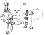
According to some embodiments of the present application, as shown in fig. 11-12, the detecting mechanism 4 includes a third positioning component 410 and a detecting component 420, the third positioning component 410 is fixedly connected to the supporting mechanism 1, the third positioning component 410 and the second positioning component 320 have the same structure and size, the detecting component 420 includes a supporting rod 421, a latch 422 and a laser sensor 423, the supporting rod 421 is fixedly connected to the base 110, the latch 422 is disposed at the top end of the supporting rod 421, and the laser sensor 423 is latched to the latch 422.
It should be noted that three detection mechanisms 4 are arranged in the full-automatic ferrule device for the micro sealing ring, and the three detection mechanisms 4 are respectively located between the two ferrule mechanisms 3, between the ferrule mechanism 3 and the material receiving mechanism 6 which are far away from the feeding mechanism 2, and between the material receiving mechanism 6 and the feeding mechanism 2.
It should be noted that the detection mechanism 4 located between the two ferrule mechanisms 3 detects the valve rod completing the ferrule through the laser sensor 423, if the sealing ring is completely sleeved in the valve rod, the valve rod is rotated to the next process through the bearing disc 120, and if the sealing ring is not completely sleeved in the valve rod, the valve rod is removed, so that the quality of the ferrule is automatically detected; the detection mechanism 4, which is located between the ferrule mechanism 3 and the material receiving mechanism 6 far away from the feeding mechanism 2, detects the valve rods through the laser sensor 423, if the sealing rings are completely sleeved into the valve rods, the bearing disc 120 rotates to the next process, if the sealing rings are not completely sleeved into the valve rods, the control unit 111 controls the rotating piece 623 to drive the fifth clamping piece 624 to rotate and not loosen the valve rods, but the fifth support 621 moves to the direction of the defective product box and then loosens the valve rods through the extension of the ninth telescopic piece 641, so that the valve rods fall into the defective product box, and the classified placement of the valve rods after being sleeved is realized; the detection mechanism 4 is positioned between the material receiving mechanism 6 and the feeding mechanism 2, the laser sensor 423 detects the workpieces on the bearing plate 120 which rotate after passing through the material receiving mechanism 6, if the workpieces have products which are not taken out, the alarm is given and the workpieces are cleared, and other foreign matters in the workpieces rotate to the first ring mechanism 3.
From this, this full-automatic lasso equipment of miniature sealing washer, at the in-process that carries out the lasso to the valve rod, laser sensor 423 through setting up in order, work piece and valve rod on bearing dish 120 detect, whether can real-timely know the valve rod and accomplish the normal assembly of sealing washer and whether bear the valve rod that has not been collected by receiving agencies 6 on the dish 120, then avoided staff's naked eye to watch on the carelessness that appears easily, make the quality of product obtain promoting, the assembly efficiency of sealing washer can improve simultaneously.
Among the correlation technique, carry out the in-process of lasso to the valve rod, all carry out the assembly of sealing washer to the valve rod both ends, and current lasso equipment is carrying out the in-process of miniature sealing washer lasso to the valve rod, often needs the manual work to overturn the valve rod, just can make the two homoenergetic of valve rod carry out the lasso operation, and manual operation has often increased staff's work burden, has leaded to valve rod lasso work efficiency to reduce simultaneously.
According to some embodiments of the present application, as shown in fig. 13-15, the turnover mechanism 5 includes a lifting assembly 510, a turnover assembly 520, and a fourth positioning assembly 530, the lifting assembly 510 includes a fourth bracket 511 and a seventh telescopic member 512, the fourth bracket 511 is fixedly connected to the base 110, the seventh telescopic member 512 is fixedly connected to the fourth bracket 511, the turnover assembly 520 includes a turnover member 521, a fourth clamping member 522, and a limiting member 523, the turnover member 521 is fixedly connected to an output end of the seventh telescopic member 512 for changing a height of the turnover member, the fourth clamping member 522 is fixedly connected to the turnover member 521, the limiting member 523 is fixedly connected to the fourth clamping member 522, the fourth positioning assembly 530 includes a fourth lifting member 531, a fourth clamping seat 532, a fourth lifting block 533, a fourth connecting rod 534, and a fourth clamping block 535, the fourth lifting member 531 is fixedly connected to the supporting mechanism 1, the fourth clamping seat 532 is fixedly connected to the supporting mechanism 1, fourth lifting block 533 is slidably connected to fourth clamping seat 532, one end of fourth link 534 is hinged to fourth lifting block 533, the other end of fourth link 534 is hinged to fourth clamping block 535, fourth link 534 is symmetrically designed, and fourth clamping block 535 is slidably connected to fourth clamping seat 532.
It should be noted that the turning mechanism 5 is located between the two ferrule mechanisms 3.
It can be understood that the seventh telescopic element 512 is in an extended state at the initial state, that is, the height of the turning element 521 is the highest at this time, and the clamping ends of the turning element 521 and the fourth clamping element 522 are both in an open state at this time, when the fourth positioning assembly 530 conveys the valve rod to the bottom end of the turning element 521, the turning element 521 is lowered by the contraction of the seventh telescopic element 512, then the turning element 521 clamps the valve rod, after the valve rod is clamped by the turning element 521, the fourth lifting element 531 is extended, so that the fourth clamping block 535 is released from clamping the valve rod by the fourth connecting rod 534, thereafter, the seventh telescopic element 512 is extended, so that the turning element 521 is lifted, after the valve rod is completely separated from the fourth clamping block 535, the turning element 521 is turned over by 180 degrees, positions of two ends of the valve rod are interchanged, then the valve rod is clamped by the fourth clamping element 522, and the clamping of the valve rod by the turning element 521 is matched, so that the valve rod can be kept in an upright state, then, the seventh telescopic member 512 is contracted, so that the valve rod descends to enter between the two fourth clamping blocks 535, then the fourth lifting member 531 is contracted, under the action of the gravity of the fourth lifting block 533, the angle of the fourth connecting rod 534 is changed, then the two fourth clamping blocks 535 clamp the valve rod, and under the action of the limiting member 523, the position of the valve rod in the vertical direction between the fourth clamping blocks 535 is ensured, so that the fourth clamping block 535 can ensure the positioning of the valve rod while clamping the valve rod, after the positioning and clamping of the valve rod are completed, the overturning member 521 and the fourth clamping member 522 release the clamping of the valve rod, the seventh telescopic member 512 is extended, so that the position of the overturning member 521 rises, and after the valve rod rises to the highest position, the overturning member 521 resets, so that the overturning action of the next valve rod is repeated.
From this, at the in-process that carries out the lasso operation to the valve rod, after the sealing washer assembly is accomplished to valve rod one end through first lasso mechanism 3, it is rotatory through bearing dish 120, with this valve rod rotation to tilting mechanism 5 department, carry out end to end exchange operation to this valve rod by tilting mechanism 5, then rotate to second lasso mechanism 3 department by bearing the valve rod of dish 120 after with this change direction again, carry out the lasso operation to the other end of this valve rod by second lasso mechanism 3, avoided the manual work to overturn the valve rod, just can make the two homoenergetic of valve rod carry out the lasso operation, the overall efficiency of valve rod lasso work has been promoted.
It should be noted that, according to the clockwise direction, the workpiece setting sequence of the full-automatic micro-seal ring sleeving device is that the first station is the feeding mechanism 2, the second station is one of the ring sleeving mechanisms 3, the third station is one of the detecting mechanisms 4, the fourth station is the turnover mechanism 5, the fifth station is another ring sleeving mechanism 3, the sixth station is a second detecting mechanism 4, the seventh station is the material receiving mechanism 6, and the last station is the last detecting mechanism 4, and the circumference is arranged on the periphery of the bearing disc 120 so as to perform the circularly reciprocating ring sleeving operation.
It should be noted that, eight parts of the first positioning assembly 230, the second positioning assembly 320, the third positioning assembly 410, the fourth positioning assembly 530 and the fifth positioning assembly 610, which are arranged on the carrier tray 120, and have the same structural size, and the eight parts are uniformly arranged on the carrier tray 120, so that after the carrier tray 120 rotates, the valve rod clamped thereon can correspondingly reach the next station.
It should be noted that, in this embodiment, the first telescopic member 223, the first lifting member 231, the fourth telescopic member 312, the fifth telescopic member 313, the sixth telescopic member 315, the second lifting member 321, the second telescopic member 344, the third telescopic member 346, the seventh telescopic member 512, the fourth lifting member 531, the fifth lifting member 611, the eighth telescopic member 622, and the ninth telescopic member 641 may be objects with similar functions, such as hydraulic cylinders, the first clamping member 224, the second clamping member 314, the third clamping member 316, the fourth clamping member 522, and the fifth clamping member 624 may be objects with similar functions, such as manipulators, the power member 130 and the driving member 332 may be related devices, such as motors, specific model specifications need to be determined according to actual specifications of the device, and a specific model selection calculation method adopts the prior art, and thus details are not repeated.
It should be noted that, in this embodiment, the control relationship between the control unit 111 and the related electrical device is the prior art, and is not described in detail herein.
Specifically, the working principle of the full-automatic micro-seal ring sleeving equipment is as follows: the valve rod is placed on the drainage plate 215 which is designed in an inclined way, the valve rod slides to the output end of the distributor 212 along the drainage plate 215, then the distributor 212 pushes the valve rod out of the feeding cabin 211 one by one, the valve rod slides to the divider 214 through the guide chute 213 which is arranged in an inclined way, then the first clamping piece 224 adjusts the specific position of the valve rod on the first bracket 221 through the electric push rod 222 and the first telescopic piece 223, the valve rod on the divider 214 is clamped, then the position is adjusted, the valve rod is placed between the first clamping blocks 235, the first clamping blocks 235 in the initial state are in a separated state, namely, the first lifting piece 231 is in an extending state at the moment, after the valve rod is placed between the first clamping blocks 235, the first lifting piece 231 contracts under the action of the self gravity, the first lifting block 233 at the moment displaces downwards on the first clamping seat 232, and then the two first connecting rods 234 which are symmetrically hinged on the first clamping seat 232 are forced to pull the first clamping blocks 235 to approach each other, the valve rod is engaged, so that the valve rod is not subjected to position change and is in a vertical state, subsequent micro sealing ring sleeving operation is convenient to perform on the valve rod, then the bearing disc 120 rotates clockwise by a set angle, so that the valve rod clamped on the first positioning assembly 230 rotates to the top end of the second lifting piece 321, then the bearing disc 120 stops rotating, meanwhile, when the valve rod is used, the blanking pipe 335 is filled with the sealing ring and then is arranged on the turntable 333 through a clamp, the sealing ring in the blanking pipe 335 can fall into a depression of the cutting disc 341 below the through hole through the corresponding arrangement of the through holes on one of the blanking pipe 335 and the limiting disc 334, then the rack 343 is driven to perform transverse displacement on the second bracket 345 through the telescopic change of the second telescopic piece 344, the gear 342 is driven to rotate, and the cutting disc 341 fixedly connected with the gear 342 rotates by taking the rotating connection position of the rack and the second bracket 345 as an axis, then the material cutting disc 341 conveys the sealing ring to the lower part of the vacuum chuck 317 on the second clamping member 314, because the bottom end position of the material cutting disc 341 is in clearance fit with the upper surface position of the second bracket 345, the upper surface position of the material cutting disc 341 is in clearance fit with the lower surface position of the limiting disc 334, and only one concave part is arranged on the material cutting disc 341, so that other sealing rings in the blanking pipe 335 are blocked in the rotation process of the material cutting disc 341, the sealing rings in the blanking pipe 335 are prevented from falling to other positions, at this time, the fifth telescopic member 313 and the second clamping member 314 thereon generate transverse displacement relative to the third bracket 311 through the telescopic change of the fourth telescopic member 312, so that the vacuum chuck 317 on the second clamping member 314 is positioned right above the sealing ring on the material cutting disc 341, and the vacuum chuck 317 is close to the sealing ring on the material cutting disc 341 through the telescopic change of the fifth telescopic member 313, the vacuum chuck 317 can suck the sealing ring conveniently, then the fourth expansion part 312 contracts to drive the second clamping part 314 to reset, at the moment, the vacuum chuck 317 on the second clamping part 314 is displaced to be right above the positioning rod 347, then the fifth expansion part 313 extends to enable the vacuum chuck 317 to be sleeved on the positioning rod 347, then the vacuum chuck 317 puts down the sealing ring in the second clamping part, meanwhile, the third expansion part 346 extends to drive the positioning rod 347 to rise, so that the sealing ring can be stably sleeved on the top of the positioning rod 347, in the process, the cutting disc 341 resets after the vacuum chuck 317 sucks the sealing ring on the cutting disc, so that the sealing ring in the discharging pipe 335 can fall to the concave part on the cutting disc 341, then the actions are repeated, the next sealing ring is rotated to the direction of the second clamping part 314 through the cutting disc 341, and the first sleeved sealing ring is behind the top of the positioning rod 347, the fourth expansion piece 312 extends to reset the second clamping piece 314 and the third clamping piece 316, at this time, the vacuum chuck 317 on the second clamping piece 314 is located above the next seal ring, the vacuum chuck 317 on the third clamping piece 316 is located above the positioning rod 347 at this time, the fifth expansion piece 313 and the sixth expansion piece 315 synchronously expand and contract, so that the two vacuum chucks 317 suck the two seal rings simultaneously and then synchronously ascend to facilitate displacement, at this time, the fourth expansion piece 312 contracts to enable the vacuum chuck 317 on the third clamping piece 316 to displace to the positioning rod 347, at this time, the vacuum chuck 317 on the third clamping piece 316 displaces to the position above the valve rod clamped by the second clamping block 325, and then the fifth expansion piece 313 and the sixth expansion piece 315 synchronously expand and contract, so that the two seal rings are completely sleeved on the positioning rod 347, one seal ring is completely sleeved on the valve rod, and the operation of automatic ferrule is completed, after the valve rod on the second clamping block 325 completes the ferrule movement, the control unit 111 controls the power member 130 to start, so that the bearing disc 120 continues to rotate clockwise by a predetermined angle, so that the valve rod completing the ferrule rotates to the next station, and at the same time, the external sensing device monitors the sealing ring in the blanking pipe 335, the external sensing device is in signal connection with the control unit 111, so as to transmit a start-stop signal to the driving member 332, after the sensing device monitors that the sealing ring in the blanking pipe 335 corresponding to the through hole on the limiting disc 334 is used, the driving member 332 is controlled to start through signal transmission, so as to drive the rotating disc 333 to rotate, so that the next blanking pipe 335 clamped on the circumferential side 333 of the rotating disc is displaced to the through hole on the limiting disc 334, so as to realize sustainable sealing ring supply, and the detection mechanism 4 located between the two ferrules 3 detects the valve rod completing the ferrule through the laser sensor 423, if the sealing ring is completely sleeved in the valve rod, the bearing disc 120 rotates to the next process, if the sealing ring is not completely sleeved in the valve rod, the sealing ring is removed, the quality of the sealing ring is automatically detected, the qualified valve rod rotates to the turnover mechanism 5 through the bearing disc 120, wherein the seventh telescopic part 512 is in an extension state in the initial state, namely the height of the turnover part 521 is the highest at the moment, the clamping ends of the turnover part 521 and the fourth clamping part 522 are both in an open state, when the fourth positioning assembly 530 conveys the valve rod to the bottom end of the turnover part 521, the seventh telescopic part 512 contracts to enable the turnover part 521 to descend, then the turnover part 521 clamps the valve rod, after the turnover part 521 clamps the valve rod, the fourth lifting part 531 extends to enable the fourth clamping block 535 to release the clamping of the valve rod under the action of the fourth connecting rod 534, and then the seventh telescopic part 512 extends to enable the turnover part 521 to ascend, after the valve rod is completely separated from the fourth clamping block 535, the overturning part 521 overturns 180 degrees, so that positions of two ends of the valve rod are exchanged, then the fourth clamping part 522 clamps the valve rod, the overturning part 521 is matched with clamping of the valve rod, so that the valve rod can be kept in a vertical state, then the seventh telescopic part 512 contracts, so that the valve rod descends to enter between the two fourth clamping blocks 535, then the fourth lifting part 531 contracts, under the action of gravity of the fourth lifting block 533, the angle of the fourth connecting rod 534 is changed, so that the two fourth clamping blocks 535 clamp the valve rod, and under the action of the limiting part 523, the position of the valve rod in the vertical direction between the fourth clamping blocks 535 is ensured, so that the fourth clamping block 535 clamps the valve rod while the valve rod can ensure the positioning of the valve rod, after the positioning and the clamping of the valve rod are completed, the overturning part 521 and the fourth clamping part 522 release the clamping of the valve rod, the seventh expansion element 512 extends to enable the position of the turnover element 521 to rise, after the turnover element 521 rises to the highest position, the turnover element 521 resets to repeat the turnover action of the next valve rod, after the valve rod is turned over, the bearing disc 120 continues to rotate to another ferrule mechanism 3 to ferrule the other end of the valve rod, after the process is completed, the bearing disc 120 rotates to enable the valve rod to rotate to a sixth station, namely a second detection mechanism 4, the valve rod is detected through the laser sensor 423, after the detection, the bearing disc 120 rotates to enable the valve rod to rotate to a receiving mechanism 6, if the sealing ring is completely sleeved in the valve rod, the eighth expansion element 622 contracts to enable the fifth clamping element 624 to clamp the valve rod on the fifth clamping block 615, then the fifth clamping block 615 extends through the fifth lifting element 611 to enable the angle of the fifth connecting rod 614 to change, and then the fifth clamping block 615 releases the valve rod, the eighth expansion element 622 extends to make the fifth clamping element 624 take the valve rod to be separated from the fifth clamping block 615, then the rotating element 623 drives the fifth clamping element 624 to rotate, so that the valve rod on the fifth clamping element 624 is released from the valve rod after facing the conveyor belt 632, so that the valve rod falls towards the conveyor belt 632, and then the valve rod is conveyed into the collecting box through the conveyor belt 632, if the sealing ring on the valve rod is not completely sleeved, the rotating element 623 drives the fifth clamping element 624 to rotate, so that the valve rod is not released, but the fifth support 621 moves towards the direction of the defective box through the extension of the ninth expansion element 641, then the fifth clamping element 624 is released, so that the valve rod falls into the defective box, then the ninth expansion element 641 retracts to reset the fifth support 621, and simultaneously the rotating element 623 drives the fifth clamping element 624 to reset and rotate, so as to repeat the above actions, the classified placement of the looped valve rod is realized, and after the classified collection of the valve rod by the collecting element 6, bear the dish 120 and rotate, the work piece with its last centre gripping valve rod rotates to last workstation, last detection mechanism 4 promptly, detect the work piece that bears the dish 120 that rotates coming through laser sensor 423, if there is the product warning that does not take out and clear away on the work piece, no other foreign matter then rotates to first lasso mechanism 3 department in the work piece, the flow is accomplished to the above-mentioned repetition, this kind of design of this equipment, make whole lasso operation realize the automation, make the assembly efficiency of sealing washer promote on the valve rod, the assembly quality can improve simultaneously.
The above description is only for the specific embodiments of the present application, but the scope of the present application is not limited thereto, and any person skilled in the art can easily conceive of the changes or substitutions within the technical scope of the present application, and shall be covered by the scope of the present application. Therefore, the protection scope of the present application shall be subject to the protection scope of the claims.
Claims (10)
1. The utility model provides a full-automatic lasso equipment of miniature sealing washer which characterized in that includes:
the supporting mechanism (1) comprises a base (110), a bearing disc (120) and a power piece (130), the bearing disc (120) is connected to the output end of the power piece (130) in a transmission mode, and one end, far away from the bearing disc (120), of the power piece (130) is fixedly connected to the base (110);
the feeding mechanism (2), the feeding mechanism (2) is arranged on the base (110);
the ferrule mechanism (3), the ferrule mechanism (3) comprises a ferrule assembly (310), a second positioning assembly (320), a feeding assembly (330) and a blanking assembly (340), the ferrule assembly (310) comprises a third support (311), a fourth telescopic member (312), a fifth telescopic member (313), a second clamping member (314), a sixth telescopic member (315), a third clamping member (316) and a vacuum chuck (317), the third support (311) is fixedly connected to the base (110), the fourth telescopic member (312) is fixedly connected to the third support (311), the fifth telescopic member (313) is fixedly connected to an output end of the fourth telescopic member (312), the second clamping member (314) is fixedly connected to an output end of the fifth telescopic member (313), and the sixth telescopic member (315) is fixedly connected to an output end of the fourth telescopic member (312), the third clamping piece (316) is fixedly connected to the output end of the sixth telescopic piece (315), the vacuum chuck (317) is respectively arranged on the second clamping piece (314) and the third clamping piece (316), the second positioning assembly (320) is fixedly connected to the supporting mechanism (1), the feeding assembly (330) is arranged on the base (110), and the cutting assembly (340) is arranged on one side of the feeding assembly (330);
the material receiving mechanism (6), the material receiving mechanism (6) is arranged on the base (110);
the detection mechanism (4), the detection mechanism (4) is fixedly connected to the base (110), and the detection mechanism (4) is used for detecting a sealing ring on the valve rod;
the turnover mechanism (5), turnover mechanism (5) fixed connection in base (110), turnover mechanism (5) are used for controlling the valve rod and carry out the upset action.
2. The full-automatic micro-seal ring ferrule device according to claim 1, wherein a control unit (111) is disposed in the base (110), and the control unit (111) performs a predetermined program operation on the electrical device in the full-automatic micro-seal ring ferrule device.
3. The full-automatic ferrule device for the micro sealing ring according to claim 1, wherein the feeding mechanism (2) comprises a feeding assembly (210), a clamping assembly (220) and a first positioning assembly (230), one end of the feeding assembly (210) is fixedly connected to the base (110), the other end of the feeding assembly (210) is obliquely arranged on the bottom side of the clamping assembly (220), the clamping assembly (220) is fixedly connected to the base (110), one part of the first positioning assembly (230) is fixedly connected to the bearing plate (120), and the other part of the first positioning assembly (230) is fixedly connected to the base (110).
4. The full-automatic ferrule device for the micro sealing ring according to claim 1, wherein the extending and retracting direction of the fourth telescopic member (312) is perpendicular to the height direction of the third support (311), the extending and retracting direction of the fifth telescopic member (313) is perpendicular to the extending and retracting direction of the fourth telescopic member (312), and the extending and retracting direction of the sixth telescopic member (315) is consistent with the extending and retracting direction of the fifth telescopic member (313).
5. The full-automatic ferrule device for the micro sealing ring according to claim 3, wherein the second positioning assembly (320) comprises a second lifting member (321), a second clamping seat (322), a second lifting block (323), a second connecting rod (324) and a second clamping block (325), the second lifting member (321) is fixedly connected to the base (110), the second clamping seat (322) is fixedly connected to the bearing plate (120), the second lifting block (323) is slidably connected to the second clamping seat (322), one end of the second connecting rod (324) is hinged to the second lifting block (323), the other end of the second connecting rod (324) is hinged to the second clamping block (325), and the second clamping block (325) is slidably connected to the second clamping seat (322).
6. The fully automatic ferrule device for micro seal ring according to claim 5, wherein the second positioning assembly (320) and the first positioning assembly (230) have the same size.
7. The full-automatic ferrule device for the micro sealing ring according to claim 5, wherein a through hole is formed in the top end of the second clamping seat (322), and the diameter of the through hole in the top end of the second clamping seat (322) is not smaller than the diameter of the valve rod.
8. The full-automatic ferrule device for the micro sealing ring according to claim 1, wherein the feed supplement assembly (330) comprises a protective shell (331), a driving member (332), a rotating disc (333), a limiting disc (334) and a feeding pipe (335), the protective shell (331) is fixedly connected to the supporting mechanism (1), the driving member (332) is fixedly connected to the protective shell (331), the rotating disc (333) is in transmission connection with an output end of the driving member (332), a hoop arranged in a circumferential array is fixedly connected to the circumferential side of the rotating disc (333), the limiting disc (334) is fixedly connected to the protective shell (331), a through hole is formed in the limiting disc (334), the output end of the driving member (332) rotates to penetrate through the limiting disc (334), and the feeding pipe (335) is clamped to the hoop fixedly connected to the circumferential side of the rotating disc (333), the blanking pipe (335) is matched with a through hole arranged on the limiting disc (334).
9. The full-automatic ferrule device for the micro sealing ring according to claim 8, wherein the cutting assembly (340) comprises a cutting disc (341), a gear (342), a rack (343), a second telescopic member (344), a second bracket (345), a third telescopic member (346) and a positioning rod (347), the cutting disc (341) is provided with a recess, the recess provided on the cutting disc (341) is matched with the through hole provided on the limiting disc (334), the cutting disc (341) is rotatably connected to the second bracket (345), the gear (342) is fixedly connected to the cutting disc (341), the gear (342) is meshed with the rack (343), the rack (343) is slidably connected to the second bracket (345), the second telescopic member (344) is fixedly connected to the second bracket (345), and the output end of the second telescopic member (344) is fixedly connected to the rack (343), the second bracket (345) is fixedly connected to the supporting mechanism (1), the third telescopic piece (346) is fixedly connected to one side, away from the second telescopic piece (344), of the second bracket (345), the output end of the third telescopic piece (346) is provided with the locating rod (347), and the top end of the locating rod (347) is in a conical design.
10. The full-automatic ferrule device for the micro sealing ring according to claim 9, wherein the receiving mechanism (6) comprises a fifth positioning assembly (610), a receiving assembly (620), a conveying assembly (630) and a push-pull assembly (640), the fifth positioning assembly (610) is disposed on the supporting mechanism (1), the fifth positioning assembly (610) and the second positioning assembly (320) have the same structural size, the receiving assembly (620) is fixedly connected to the base (110), the conveying assembly (630) is fixedly connected to the base (110), one end of the push-pull assembly (640) is fixedly connected to the base (110), and the other end of the push-pull assembly (640) is fixedly connected to the bottom of the receiving assembly (620).
Priority Applications (1)
| Application Number | Priority Date | Filing Date | Title |
|---|---|---|---|
| CN202210592714.0A CN114888565B (en) | 2022-05-27 | 2022-05-27 | Full-automatic lasso equipment of miniature sealing washer |
Applications Claiming Priority (1)
| Application Number | Priority Date | Filing Date | Title |
|---|---|---|---|
| CN202210592714.0A CN114888565B (en) | 2022-05-27 | 2022-05-27 | Full-automatic lasso equipment of miniature sealing washer |
Publications (2)
| Publication Number | Publication Date |
|---|---|
| CN114888565A true CN114888565A (en) | 2022-08-12 |
| CN114888565B CN114888565B (en) | 2023-05-16 |
Family
ID=82725402
Family Applications (1)
| Application Number | Title | Priority Date | Filing Date |
|---|---|---|---|
| CN202210592714.0A Active CN114888565B (en) | 2022-05-27 | 2022-05-27 | Full-automatic lasso equipment of miniature sealing washer |
Country Status (1)
| Country | Link |
|---|---|
| CN (1) | CN114888565B (en) |
Citations (8)
| Publication number | Priority date | Publication date | Assignee | Title |
|---|---|---|---|---|
| US5038463A (en) * | 1988-03-17 | 1991-08-13 | Honda Giken Kogyo Kabushiki Kaisha | Apparatus for assembling a vehicular drive shaft |
| CN204075698U (en) * | 2014-08-19 | 2015-01-07 | 广东华声电器股份有限公司 | photovoltaic cable connector automatic assembly equipment |
| CN105834740A (en) * | 2016-05-18 | 2016-08-10 | 宁波盛达阳光气动机械有限公司 | Multi-station automatic assembly machine for valve rod sealing rings |
| CN207013988U (en) * | 2017-07-26 | 2018-02-16 | 余姚市耐德自动化科技有限公司 | Water-leakage basket assembly machine |
| CN108115401A (en) * | 2017-12-18 | 2018-06-05 | 袁福德 | A kind of automatic assembly method of rubber ring |
| CN109956300A (en) * | 2019-03-26 | 2019-07-02 | 昆山庄正精密机械有限公司 | A kind of cylinder seal circle feeding device |
| CN110802390A (en) * | 2019-10-22 | 2020-02-18 | 丽水市盛裕机械制造有限公司 | Be used for two-way O type sealing washer suit equipment of tubulose work piece |
| CN214212812U (en) * | 2020-12-07 | 2021-09-17 | 青岛泰萌自动化设备有限公司 | Sealing ring feeding machine |
-
2022
- 2022-05-27 CN CN202210592714.0A patent/CN114888565B/en active Active
Patent Citations (8)
| Publication number | Priority date | Publication date | Assignee | Title |
|---|---|---|---|---|
| US5038463A (en) * | 1988-03-17 | 1991-08-13 | Honda Giken Kogyo Kabushiki Kaisha | Apparatus for assembling a vehicular drive shaft |
| CN204075698U (en) * | 2014-08-19 | 2015-01-07 | 广东华声电器股份有限公司 | photovoltaic cable connector automatic assembly equipment |
| CN105834740A (en) * | 2016-05-18 | 2016-08-10 | 宁波盛达阳光气动机械有限公司 | Multi-station automatic assembly machine for valve rod sealing rings |
| CN207013988U (en) * | 2017-07-26 | 2018-02-16 | 余姚市耐德自动化科技有限公司 | Water-leakage basket assembly machine |
| CN108115401A (en) * | 2017-12-18 | 2018-06-05 | 袁福德 | A kind of automatic assembly method of rubber ring |
| CN109956300A (en) * | 2019-03-26 | 2019-07-02 | 昆山庄正精密机械有限公司 | A kind of cylinder seal circle feeding device |
| CN110802390A (en) * | 2019-10-22 | 2020-02-18 | 丽水市盛裕机械制造有限公司 | Be used for two-way O type sealing washer suit equipment of tubulose work piece |
| CN214212812U (en) * | 2020-12-07 | 2021-09-17 | 青岛泰萌自动化设备有限公司 | Sealing ring feeding machine |
Also Published As
| Publication number | Publication date |
|---|---|
| CN114888565B (en) | 2023-05-16 |
Similar Documents
| Publication | Publication Date | Title |
|---|---|---|
| CN107717443B (en) | Pilot valve automatic assembling and detection device | |
| CN107363530B (en) | O-shaped ring assembling equipment | |
| CN109202441A (en) | A kind of servo motor assemble method and system | |
| CN103972590B (en) | The automatic material receiving of up-coiler and disc loading apparatus | |
| CN107020513B (en) | Automatic coffee cup assembling and hot melting machine | |
| CN107052819B (en) | Automatic production line | |
| CN216780908U (en) | Valve core assembling equipment | |
| CN110654600B (en) | Electric cooker packaging production line | |
| CN109531148A (en) | A kind of heating power expansion valve automatic assembly equipment | |
| CN111092141A (en) | Solid crystal picking and packaging device | |
| CN112871727A (en) | Bearing assembling equipment | |
| CN112496524A (en) | Automatic steel bar welding equipment | |
| CN114888565A (en) | Full-automatic ferrule equipment of miniature sealing washer | |
| CN209867849U (en) | Full-automatic bobbin case assembly quality | |
| CN209078082U (en) | A kind of square pile flange automatic soldering device | |
| CN215200513U (en) | Multifunctional shower head assembling machine | |
| CN106667016B (en) | Toilet brush feather planting machine automatic loading and unloading device | |
| CN108788568A (en) | Precision component welds center | |
| CN212169567U (en) | Automatic insulator assembling equipment | |
| CN215316797U (en) | Full-automatic assembling equipment | |
| CN211150594U (en) | Solid crystal picking and packaging device | |
| CN109352154B (en) | Automatic welding equipment for stainless steel cup | |
| CN209840956U (en) | Air bag igniter shell through hole detection machine | |
| CN209664523U (en) | Reflow Soldering automatic feed mechanism | |
| CN113155035A (en) | Appearance detection device for CNC (computer numerical control) product |
Legal Events
| Date | Code | Title | Description |
|---|---|---|---|
| PB01 | Publication | ||
| PB01 | Publication | ||
| SE01 | Entry into force of request for substantive examination | ||
| SE01 | Entry into force of request for substantive examination | ||
| GR01 | Patent grant | ||
| GR01 | Patent grant |