CN114871893A - Medical coaptation board grinding device that becomes more meticulous - Google Patents
Medical coaptation board grinding device that becomes more meticulous Download PDFInfo
- Publication number
- CN114871893A CN114871893A CN202210797797.7A CN202210797797A CN114871893A CN 114871893 A CN114871893 A CN 114871893A CN 202210797797 A CN202210797797 A CN 202210797797A CN 114871893 A CN114871893 A CN 114871893A
- Authority
- CN
- China
- Prior art keywords
- driving
- gear
- grinding
- sliding
- rack
- Prior art date
- Legal status (The legal status is an assumption and is not a legal conclusion. Google has not performed a legal analysis and makes no representation as to the accuracy of the status listed.)
- Pending
Links
Images


Classifications
-
- B—PERFORMING OPERATIONS; TRANSPORTING
- B24—GRINDING; POLISHING
- B24B—MACHINES, DEVICES, OR PROCESSES FOR GRINDING OR POLISHING; DRESSING OR CONDITIONING OF ABRADING SURFACES; FEEDING OF GRINDING, POLISHING, OR LAPPING AGENTS
- B24B9/00—Machines or devices designed for grinding edges or bevels on work or for removing burrs; Accessories therefor
- B24B9/02—Machines or devices designed for grinding edges or bevels on work or for removing burrs; Accessories therefor characterised by a special design with respect to properties of materials specific to articles to be ground
- B24B9/04—Machines or devices designed for grinding edges or bevels on work or for removing burrs; Accessories therefor characterised by a special design with respect to properties of materials specific to articles to be ground of metal, e.g. skate blades
-
- B—PERFORMING OPERATIONS; TRANSPORTING
- B24—GRINDING; POLISHING
- B24B—MACHINES, DEVICES, OR PROCESSES FOR GRINDING OR POLISHING; DRESSING OR CONDITIONING OF ABRADING SURFACES; FEEDING OF GRINDING, POLISHING, OR LAPPING AGENTS
- B24B27/00—Other grinding machines or devices
- B24B27/0076—Other grinding machines or devices grinding machines comprising two or more grinding tools
-
- B—PERFORMING OPERATIONS; TRANSPORTING
- B24—GRINDING; POLISHING
- B24B—MACHINES, DEVICES, OR PROCESSES FOR GRINDING OR POLISHING; DRESSING OR CONDITIONING OF ABRADING SURFACES; FEEDING OF GRINDING, POLISHING, OR LAPPING AGENTS
- B24B41/00—Component parts such as frames, beds, carriages, headstocks
- B24B41/06—Work supports, e.g. adjustable steadies
-
- B—PERFORMING OPERATIONS; TRANSPORTING
- B24—GRINDING; POLISHING
- B24B—MACHINES, DEVICES, OR PROCESSES FOR GRINDING OR POLISHING; DRESSING OR CONDITIONING OF ABRADING SURFACES; FEEDING OF GRINDING, POLISHING, OR LAPPING AGENTS
- B24B47/00—Drives or gearings; Equipment therefor
- B24B47/10—Drives or gearings; Equipment therefor for rotating or reciprocating working-spindles carrying grinding wheels or workpieces
- B24B47/12—Drives or gearings; Equipment therefor for rotating or reciprocating working-spindles carrying grinding wheels or workpieces by mechanical gearing or electric power
-
- B—PERFORMING OPERATIONS; TRANSPORTING
- B24—GRINDING; POLISHING
- B24B—MACHINES, DEVICES, OR PROCESSES FOR GRINDING OR POLISHING; DRESSING OR CONDITIONING OF ABRADING SURFACES; FEEDING OF GRINDING, POLISHING, OR LAPPING AGENTS
- B24B55/00—Safety devices for grinding or polishing machines; Accessories fitted to grinding or polishing machines for keeping tools or parts of the machine in good working condition
Abstract
The invention discloses a fine grinding device for a medical bone fracture plate, which belongs to the technical field of processing of orthopedic bone fracture plates and comprises a plurality of grinding assemblies, a driving assembly for driving the grinding assemblies to move and a clamping piece for clamping workpieces, wherein the grinding assemblies comprise a first grinding piece and a second grinding piece which are opposite in sliding direction; the base is provided with a lead screw parallel to the slide rail, the lead screw is provided with a first slide block, the first slide block is provided with a first rack, the slide rail is provided with a sliding table, the two sides of the sliding table are provided with a second rack, a first support is arranged between the first slide block and the slide rail, the first support is provided with a connecting shaft gear set, the connecting shaft gear set is respectively meshed with the first rack and the second rack and is connected with the first rack and the second rack, the first polishing part is arranged on the sliding table of the first driving part, and the thread directions of the lead screw of the first driving part and the lead screw of the second driving part are opposite.
Description
Technical Field
The invention relates to the technical field of processing of bone fracture plates, in particular to a fine polishing device for a medical bone fracture plate.
Background
The metal bone fracture plate (supporting bone fracture plate) is mainly used for treating extremity metaphysis fracture diseases in orthopedics and is used for fixing or supporting the fracture part in the operation. Under the matching use of the bone screw, the bone screw is used as a fracture part for anatomical reduction connection so as to achieve the effect of assisting fracture healing.
The prior art aims at grinding devices of the metal bone fracture plate, such as the grinding device disclosed in CN112959194 and the grinding device disclosed in CN111168492, only aim at grinding and deburring a circular hole groove, while the common locking pressure combination holes in the bone fracture plate are two partially overlapped holes with different diameters, and the prior art also lacks the grinding device of the hole groove aiming at the hole groove with the shape.
Disclosure of Invention
In order to solve the technical problems, the invention adopts the following technical scheme: the invention provides a medical bone fracture plate refining polishing device which is characterized by comprising a plurality of polishing components, a driving component for driving the polishing components to move and a clamping piece for clamping a workpiece, wherein the polishing components comprise a first polishing piece and a second polishing piece which are opposite in sliding direction, the driving component comprises a first driving piece and a second driving piece for driving the first polishing piece and the second polishing piece to slide, and the first driving piece and the second driving piece both comprise: the device comprises a base, a screw rod and a sliding table; the base is provided with a slide rail, a first slide groove is formed in the middle of the slide rail, a lead screw parallel to the slide rail is arranged in the first slide groove, a first slide block is arranged on the lead screw, a first rack is arranged on the first slide block, a sliding table is arranged on the slide rail, second racks parallel to the first racks are arranged on two sides of the sliding table, a first support is arranged between the first slide groove and the slide rail, a connecting shaft gear set is arranged on the first support, the middle of the connecting shaft gear set is meshed with the first rack, two ends of the connecting shaft gear set are meshed with the second racks, the first polishing piece and the second polishing piece are arranged on the sliding table of the first driving piece and the second driving piece respectively, the screw thread directions of the lead screw of the first driving piece and the second driving piece are opposite, and a clamping piece is arranged on the base.
Preferably, the first polishing part and the second polishing part both comprise a polishing roller and a shell, an umbrella-shaped driving assembly for driving the polishing roller to rotate is arranged inside the shell, a polishing roller is arranged on a rotating shaft of an umbrella-shaped gear of the umbrella-shaped driving assembly, and the radius of the polishing roller of the first polishing part is larger than that of the polishing roller of the second polishing part.
Preferably, in order to prevent the first polishing member and the second polishing member from shaking in the sliding process after the polishing operation is completed, the rotating polishing roller continues to rotate to polish the surface of the bone plate, so that the precision is poor, a second support and a third support are further arranged between the first sliding groove and the sliding rail, a second rotating shaft perpendicular to the base is arranged on the third support, a driving ratchet gear slidably connected with the second rotating shaft is arranged on the second rotating shaft, a driven ratchet gear is arranged at one end, away from the polishing roller, of the umbrella-shaped driving assembly, a second sliding groove is arranged around the periphery of the driving ratchet gear, a shifting lever rotatably connected with the second support is arranged on the second support, a second sliding block rotatably connected with the shifting lever is arranged at one end, close to the driving ratchet gear, of the shifting lever, a connecting rod rotatably connected with a first rack is arranged at one end, close to the driving ratchet gear, of the first rack, of the shifting lever, and the second sliding block and the second sliding groove are arranged at one end of the shifting lever, close to the driving ratchet gear, of the second rack, and the second sliding rod is arranged at the other end of the shifting lever, close to the driving ratchet gear The other end of the connecting rod is rotatably connected with one end of the shifting rod, which is far away from the driving ratchet gear, and one end of the connecting rod, which is close to the driving ratchet gear, is provided with an open notch.
Preferably, a first triangular block with a central line perpendicular to the rod body of the shifting lever is arranged in the middle of the shifting lever, a column cavity is arranged at one end, away from the base, of the second support, a second triangular block slidably connected with the column cavity is arranged in the column cavity, and a spring abutted against the second triangular block is arranged in the column cavity.
Preferably, the connecting shaft gear set comprises a first gear and a second gear which are coaxially connected, the two ends of the first gear are respectively provided with a second gear which is coaxial, and the second gear is a half gear.
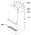
Preferably, after finishing polishing the main hole of the combined pressurizing hole, the bone fracture plate is moved by a proper distance to polish the auxiliary hole of the combined pressurizing hole, the clamping piece comprises a clamping arm and a third sliding groove, the third sliding groove is perpendicular to the sliding rail, the clamping arm is slidably arranged in the third sliding groove, the clamping arm is provided with a U-shaped clamping groove, one side wall of the clamping groove is provided with a clamping plate and an adjusting screw, two ends of the clamping plate are slidably connected with the side wall of the clamping groove through a sliding rod, and the adjusting screw penetrates through the side wall of the clamping groove to abut against the clamping plate.
Preferably, a third rack is arranged on the side face of the clamping arm, one end of the screw rod penetrates through the base to enter the third sliding groove, a third gear meshed with the third rack is arranged at one end of the screw rod entering the third sliding groove, and the third gear is a half gear.
Preferably, a fourth gear for driving the second rotating shaft to rotate is arranged on the second rotating shaft.
Preferably, a belt pulley is arranged at one end, extending out of the first sliding groove, of the screw rod, and a driving motor for driving the belt pulley to rotate is arranged on the base.
The invention has the beneficial effects that: 1. the bone fracture plate comprises a first grinding piece and a second grinding piece which are opposite in sliding direction, so that the fine processing of the combined pressurizing hole of the bone fracture plate can be realized; 2. according to the invention, through the matching of the structures, the precision difference caused by the influence on other parts of the bone fracture plate when the first polishing piece and the second polishing piece are polished can be effectively prevented; 3. the invention can realize full-automatic fine treatment of the combined pressurizing hole of the bone fracture plate through mutual matching of the structures; 4. the invention can simultaneously finish the automatic grinding of the main holes and the auxiliary holes of a plurality of combined pressurizing holes of the bone fracture plate, thereby improving the working efficiency and the processing precision.
Drawings
In order to more clearly illustrate the embodiments of the present invention or the technical solutions in the prior art, the drawings used in the description of the embodiments or the prior art will be briefly described below, it is obvious that the drawings in the following description are only some embodiments of the present invention, and for those skilled in the art, other drawings can be obtained according to the drawings without creative efforts.
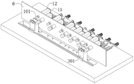
Fig. 1 is a structural schematic diagram of a medical bone fracture plate refining polishing device provided by an embodiment of the invention matched with a bone fracture plate.
Fig. 2 is a first perspective structural view of a medical bone fracture plate refining grinding device according to an embodiment of the present invention.
Fig. 3 is a left side view of a structure of a medical bone fracture plate refining grinding device according to an embodiment of the present invention.
Fig. 4 is an enlarged view of a portion a in fig. 3.
Fig. 5 is a second perspective structural view of a medical bone plate refining and polishing device according to an embodiment of the present invention.
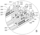
Fig. 6 is an enlarged view of a portion B in fig. 5.
Fig. 7 is a left side sectional view of a first working state of the structure of the medical bone plate refining grinding device provided by the embodiment of the invention.
Fig. 8 is an enlarged view of a portion C in fig. 7.
Fig. 9 is a left side sectional view of a second working state of the structure of the medical bone plate refining grinding device provided by the embodiment of the invention.
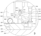
Fig. 10 is an enlarged view of a portion D in fig. 9.
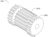
Fig. 11 is a schematic structural view of a coupling gear set of a medical bone fracture plate refining polishing device according to an embodiment of the present invention.
Fig. 12 is a schematic structural view of a clamping arm of a medical bone plate refining and grinding device according to an embodiment of the present invention.
Fig. 13 is a schematic connection rod diagram of a medical bone fracture plate refining polishing device according to an embodiment of the present invention.
Fig. 14 is a structural diagram of a bone plate for posterior-lateral two-post fixation and locking of a distal humerus in the prior art.
Description of reference numerals: a first polishing member 11; a second grinding member 12; polishing the roller 101; a housing 102; an umbrella drive assembly 103; the driven ratchet-gear 104; a base 201; a slide rail 202; a screw rod 203; a first slider 204; a first rack 205; a slide table 206; a second rack 207; a first bracket 208; a coupling gear set 209; first gear 2091; second gear 2092; a second bracket 210; a third bracket 211; a second rotating shaft 212; the driving ratchet gear 213; a shift lever 214; a second slider 215; a connecting rod 216; a first triangular block 217; the column cavity 218; a second triangular block 219; a spring 220; a notch 221; a second chute 222; a fourth gear 223; a pulley 224; a drive motor 225; a first chute 226; a clamp arm 301; a third chute 302; a third rack 303; a third gear 304; a holding groove 305; a clamping plate 306; adjusting screws 307, bone plate 4; a pressure coupling hole 5; supporting the baffle 6.
Detailed Description
The technical solutions in the embodiments of the present invention will be clearly and completely described below with reference to the drawings in the embodiments of the present invention, and it is obvious that the described embodiments are only a part of the embodiments of the present invention, and not all of the embodiments. All other embodiments, which can be derived by a person skilled in the art from the embodiments given herein without making any creative effort, shall fall within the protection scope of the present invention.
Example 1: as shown in fig. 1 to 10 and 14, the invention provides a medical bone plate refining grinding device, which comprises a plurality of grinding assemblies, a driving assembly for driving the grinding assemblies to move and a clamping piece for clamping workpieces, wherein the grinding assemblies comprise a first grinding piece 11 and a second grinding piece 12 which slide in opposite directions, after the first grinding piece 11 finishes grinding a bone plate 4, the first grinding piece 11 is far away from the bone plate 4, the second grinding piece 12 starts to approach the bone plate 4, the driving assembly drives the first grinding piece 11 and the second grinding piece 12 to slide in opposite directions, as shown in fig. 14, the bone plate 4 comprises a bone plate main body and a pressure combination hole 5 on the bone plate 4, the pressure combination hole 5 comprises a main hole and an auxiliary hole, the main hole and the auxiliary hole are overlapped, the radius of the main hole is larger than that of the auxiliary hole, the first grinding piece 11 and the second grinding piece 12 are respectively used for grinding the main hole and the auxiliary hole, the driving assembly comprises a first driving member and a second driving member for driving the first grinding member 11 and the second grinding member 12 to slide, and the first driving member and the second driving member each comprise: base 201, lead screw 203 and slip table 206 specifically are: a slide rail 202 is arranged on a base 201, a first slide groove 226 is arranged in the middle of the slide rail 202, a screw rod 203 parallel to the slide rail 202 is arranged in the first slide groove 226, a first slide block 204 is arranged on the screw rod 203, the screw rod 203 can drive the first slide block 204 to slide along the first slide groove 226 in a rotating mode, a first rack 205 is arranged on the first slide block 204, the first rack 205 is parallel to the screw rod, the first rack 205 and the first slide block 204 synchronously slide, a sliding table 206 is arranged on the slide rail 202, second racks 207 parallel to the first rack 205 are arranged on two sides of the sliding table 206, a first support 208 is arranged between the first slide groove 226 and the slide rail 202, a connecting shaft gear set 209 is arranged on the first support 208, the middle of the connecting shaft gear set 209 is in meshed connection with the first rack 205, the first rack 205 drives the connecting shaft gear set 209 to rotate through the middle of the connecting shaft gear set 209, two ends of the connecting shaft gear set 209 are respectively in meshed connection with the second rack 207, and the first slide block 204 is arranged on the first slide rail 205, The connecting gear set 209 and the second rack 207 drive the sliding table 206 to slide along the sliding rail 202; the first polishing element 11 and the second polishing element 12 are respectively disposed on the sliding table 206 of the first driving element and the second driving element, the side wall of the sliding table 206 away from the base 201 is a frame structure, in other words, the upper surface of the sliding table 206 (i.e. the side wall of the sliding table 206 away from the base 201) is a supporting frame, the shape of the supporting frame is used for fixing the shape of the sliding table 206, so as to slide on the sliding rail 202, and meanwhile, the upper surface of the sliding table 206 provides support for the first polishing element 11 and the second polishing element 12, so as to drive the first polishing element 11 and the second polishing element 12 to slide. In the invention, the screw rod 203 of the first driving piece and the screw rod 203 of the second driving piece have opposite thread directions, the sliding table 206 is driven by the screw rod 203 to slide through a sliding block 204, a first rack 205, a connecting gear set 209 and a second rack 207 to slide along a sliding rail 202, the screw rod 203 of the first driving piece and the second driving piece can drive the first grinding piece 11 and the second grinding piece 12 to slide in opposite directions, and the clamping piece is used for clamping the bone fracture plate 4 to be processed.
Further, the first polishing member 11 and the second polishing member 12 both include a polishing roller 101 and a housing 102, an umbrella-shaped driving assembly 103 for driving the polishing roller 101 to rotate is disposed inside the housing 102, a polishing roller 101 is disposed on a rotating shaft of a bevel gear of the umbrella-shaped driving assembly 103, in other words, the polishing roller 101 is mounted on a rotating shaft of a bevel gear of the umbrella-shaped driving assembly 103, and an external rotating motor rotates to drive the umbrella-shaped driving assembly 103 to rotate, so as to drive the polishing roller 101 to rotate, the polishing roller 101 is a prior art in the field, and is used for polishing and flattening burrs in the rough blank pressurizing and combining hole 5 of the metal bone fracture plate 4, and the radius of the polishing roller 101 of the first polishing member 11 is greater than that of the polishing roller 101 of the second polishing member 12, so as to polish the main hole and burrs of the pressurizing and combining hole 5 for locking respectively.
Further, still be equipped with supporting baffle 6 on the base 201, supporting baffle 6 is last be equipped with the subassembly complex a plurality of cylinder holes of polishing.
Example 2: as shown in fig. 3 to 8 and 13, on the basis of embodiment 1, in order to prevent the first grinding member 11 and the second grinding member 12 from shaking during the sliding process after the grinding operation is completed, the following scheme is adopted in the invention, in which the rotating grinding roller 101 continues to rotate to grind the surface of the bone plate 4, so that the precision is poor: the coupling gear set 209 includes a first gear 2091 and a second gear 2092 coaxially connected, two ends of the first gear 2091 are respectively provided with a second gear 2092 coaxially, the second gear 2092 is a half gear, one half of the outer circumferential surface of the second gear 2092 covers teeth, the other half is a smooth surface, in this embodiment, "one half of the surface" is only used to explain the technical scheme of the present invention, and does not limit the technical scheme of the present invention, in actual operation, that is, there is smooth surface second gear 2092 surface, it can not totally cover the tooth, tooth is totally covered to first gear 2091 outer circumference, first gear 2091 meshes with first rack 205 all the time, first rack 205 slides and can drive first gear 2091 and rotate, second gear 2092 is the half-gear, thereby first rack 205 drives first gear 2092 and rotates certain angle back second gear 2092 and second rack 207 meshing drive slip table 206 and slide.
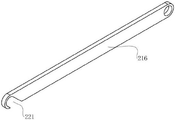
Further, a second bracket 210 and a third bracket 211 are disposed between the first sliding slot 226 and the sliding rail 202, a second rotating shaft 212 perpendicular to the base 201 is disposed on the third bracket 211, a driving ratchet gear 213 slidably connected to the second rotating shaft 212 is disposed on the second rotating shaft 212, a driven ratchet gear 104 (the driving ratchet gear is a prior art and is not described here), an output end of an external rotating motor can be connected to the driving ratchet gear 213, the driven ratchet gear 104 cooperates with the driving ratchet gear 213 to drive the umbrella-shaped driving assembly 103 to rotate, so as to drive the polishing roller 101 to rotate, a second sliding slot 222 is disposed around the periphery of the driving ratchet gear 213, a driving lever 214 rotatably connected to the second bracket 210 is disposed on the second bracket 210, a second slider 215 rotatably connected to the driving lever 214 is disposed at an end of the driving lever 214 close to the driving ratchet gear 213, the driving lever 214 is slidably connected to the outer wall of the driving ratchet gear 213 through the second sliding block 215 and the second sliding slot 222, and the driving lever 214 rotates around the second bracket 210 to drive the driving ratchet gear 213 to slide up and down along the second rotating shaft 212, so as to engage or disengage the driving ratchet gear 213 with or from the driven ratchet gear 104; in order to realize the automatic separation of the driving ratchet gear 213 and the driven ratchet gear 104 during the grinding process, a connecting rod 216 with one end rotatably connected to the first rack 205 is disposed at one end of the first rack 205 close to the driving ratchet gear 213, the other end of the connecting rod 216 is rotatably connected to one end of the driving lever 214 away from the driving ratchet gear 213, and the first rack 205 can slide to drive the driving lever 214 to rotate around the second bracket 210 through the connecting rod 216. Through the matching of the first gear 2091 and the second gear 2092, the first rack 205 slides away from the bone plate 4, the first rack 205 drives one end of the shift lever 214 away from the driving ratchet gear 213 to rotate upwards around the first bracket 210 through the connecting rod 216, the shift lever 214 drives the driving ratchet gear 213 to slide downwards along the second rotating shaft 212 and away from the driven ratchet gear 104, the first rack 205 cannot drive the sliding table 206 to slide through the connecting shaft gear set 209, at this time, the driving ratchet gear 213 is away from the driven ratchet gear 104 first and is disconnected, the transmission structure is prevented from being damaged by the rotating shearing force, and because of the limitation of the connecting rod 216 and the third bracket 211, the first rack 205 cannot slide continuously, one end of the connecting rod 216 close to the driving ratchet gear 213 is provided with the open notch 221, the notch 221 is in a bent hook shape, after the first rack 205 drives the shift lever 214 to rotate, the side surface of the notch 221 is in a horizontal state, at this time, the first rack 205 can be disconnected from the connecting rod 216, the sliding is continued, so that the sliding table 206 is driven to slide through the connecting shaft gear set 209, and the polishing roller 101 which is finished is driven to be far away from the bone fracture plate 4, and on the contrary, when the first rack 205 slides to approach the bone fracture plate 4, the first rack 205 drives the connecting gear set 209 to rotate, drives the sliding table 206 to slide, since the second gear 2092 is a half gear, the sliding platform 206 stops after sliding a distance, the first rack 205 can continue to slide along with the first slider 204, and then one end of the first rack 205 close to the driving ratchet gear 213 slightly hits the notch 221 of the connecting rod 216 and drives one end of the shift lever 214 far away from the driving ratchet gear 213 to rotate downwards through the connecting rod 216, and one end of the shift lever 214 close to the driving ratchet gear 213 drives the driving ratchet gear 213 close to the driven ratchet gear 104, so as to realize the aligned engagement between the driving ratchet gear 213 and the driven ratchet gear 104, thereby realizing the automatic control of the start rotation or stop rotation of the grinding roller 101.
Further, as shown in fig. 9 to 10, a first triangular block 217 whose central line is perpendicular to the rod body of the shift lever 214 is disposed in the middle of the shift lever 214, a cylindrical cavity 218 is disposed at an end of the second bracket 210 away from the base 1, a second triangular block 219 slidably connected to the cylindrical cavity 218 is disposed in the cylindrical cavity 218, a spring 220 abutting against the second triangular block 219 is disposed in the cylindrical cavity 218, the first triangular block 217 is staggered at the top of the second triangular block 219, and the shift lever 214 is fixed so that the shift lever 214 cannot rotate freely with the aid of the spring 220.
Example 3: as shown in fig. 7, 11, 12 and 14, the compression combination hole 5 of the bone plate is an 8-shaped hole with a part of the area intersected, after the grinding of the main hole of the combination compression hole 5 is completed, the bone plate 4 needs to be moved for a proper distance to grind the auxiliary hole of the combination compression hole 5, and based on the following scheme is adopted on the basis of the embodiment 2: the clamping piece comprises a clamping arm 301 and a third sliding groove 302, the third sliding groove 302 is perpendicular to the sliding rail 202, the clamping arm 301 is slidably arranged in the third sliding groove 302, the clamping arm 301 slides along the third sliding groove 302 to drive the bone fracture plate 4 to slide for a proper distance, a U-shaped clamping groove 305 is formed in the clamping arm 301, a clamping plate 306 and an adjusting screw 307 are arranged on one side wall of the clamping groove 305, two ends of the clamping plate 306 are slidably connected with the side wall of the clamping groove 305 through a sliding rod or a polished rod, the adjusting screw 307 penetrates through the side wall of the clamping groove 305 to abut against the clamping plate 306, the clamping plate 306 is in close contact with the surface of the bone fracture plate 4 through the adjusting screw bone fracture plate 307, the bone fracture plate 4 is fixed on the clamping groove 305 of the clamping arm 301, the clamping plate 306 prevents the adjusting screw from directly abutting against the surface of the bone fracture plate 4 to damage the surface of the bone fracture plate 4, the bone fracture plate 4 is not flat, and is not convenient for subsequent grinding work, and the surface of the clamping plate 306 close to the bone fracture plate 4 can be covered with an elastic layer.
Further, a third rack 303 is arranged on the side surface of the clamping arm 301, one end of the screw rod 203 penetrates through the base 201 and enters the third chute 302, a third gear 304 meshed with the third rack 303 is arranged at one end of the screw rod 203 extending into the third chute 302, the third gear 304 is a half gear, similarly to the embodiment 2, the screw rod 203 rotates to drive the third gear 304 to rotate, the clamping arm can be driven to slide along the third chute 302, the bone plate 4 can automatically move for a certain distance, during grinding, because the grinding roller 101 extends into the pressurizing combination hole 5, the rotation of the screw rod 203 firstly stops the rotation of the grinding roller 101, the grinding roller 101 cannot be driven to be far away from the bone plate 4, at the moment, the grinding roller 101 is driven to slide for a proper distance by the rotation of the screw rod 203, the grinding roller 101 is broken or bent, so the third gear 304 is a half gear, the third gear 304 is meshed with the third rack 303 after the grinding roller 101 is driven to be far away from the bone plate 4 by the sliding table 206, and then the third gear can slide for a proper distance, thereby completely realizing the automatic grinding process of the compression bonding hole 5 of the bone plate 4.
Further, a fourth gear 223 is disposed on the second shaft 212 for driving the second shaft 212 to rotate, and the external rotating motor can drive the second shaft 212 to rotate through the fourth gear 223, so as to drive the driving ratchet gear 213 to rotate.
Further, a belt pulley 224 is disposed at an end of the screw 203 extending out of the first chute 226 (or the screw 203 is far away from the third chute 302), a driving motor 225 for driving the belt pulley 224 to rotate is disposed on the base 201, and the driving motor 225 drives the screw 203 of the driving assembly to rotate through the belt pulley 224 (a part of a belt is not shown in the figure).
When the automatic grinding device is used, the clamping plate 306 is in close contact with the surface of the bone fracture plate 4 through the adjusting screw 307, the bone fracture plate 4 is fixed on the clamping groove 305 of the clamping arm 301, the driving motor 225 is adjusted to enable the grinding roller 101 of the first grinding piece 11 to extend into the main hole of the pressurization combination hole 5 of the bone fracture plate 4, grinding of the main hole of the pressurization combination hole 5 is achieved, after grinding of the main hole of the pressurization combination hole 5 is completed, the driving motor 225 is adjusted to rotate reversely, the first grinding piece 11 stops rotating and is far away from the main hole of the pressurization combination hole 5 of the bone fracture plate 4, the lead screw 203 drives the bone fracture plate 4 to move for a proper distance, and the second grinding piece 12 is close to the auxiliary hole of the pressurization combination hole 5 of the bone fracture plate 4, so that automatic grinding of the main holes and the auxiliary holes of a plurality of pressurization combination holes 5 is completed simultaneously.
It will be apparent to those skilled in the art that various changes and modifications may be made in the present invention without departing from the spirit and scope of the invention. Thus, if such modifications and variations of the present invention fall within the scope of the claims of the present invention and their equivalents, the present invention is also intended to include such modifications and variations.
Claims (9)
1. The utility model provides a medical coaptation board grinding device that becomes more meticulous, its characterized in that includes a plurality of subassemblies of polishing, the drive assembly that the drive subassembly that drives the subassembly of polishing removed and the holder of centre gripping work piece, the subassembly of polishing includes that the slip direction is opposite first polishes (11) and second polishes (12), the drive assembly is including driving first polishes (11) and second polishes gliding first driving piece and second driving piece of (12), first driving piece and second driving piece all include: the device comprises a base (201), a screw rod (203) and a sliding table (206); the polishing machine is characterized in that a sliding rail (202) is arranged on the base (201), a first sliding groove (226) is arranged in the middle of the sliding rail (202), a lead screw (203) parallel to the sliding rail (202) is arranged in the first sliding groove (226), a first sliding block (204) is arranged on the lead screw (203), a first rack (205) is arranged on the first sliding block (204), a sliding table (206) is arranged on the sliding rail (202), second racks (207) parallel to the first racks (205) are arranged on two sides of the sliding table (206), a first support (208) is arranged between the first sliding groove (226) and the sliding rail (202), a connecting shaft gear set (209) is arranged on the first support (208), the middle of the connecting shaft gear set (209) is meshed with the first racks (205), two ends of the connecting shaft gear set are meshed with the second racks (207), the first polishing piece (11) and the second polishing piece (12) are respectively arranged on the sliding tables (206) of the first driving piece and the second driving piece, the screw thread directions of the screw rods (203) of the first driving piece and the second driving piece are opposite, and the base (201) is further provided with a clamping piece.
2. The medical bone plate fine grinding device as claimed in claim 1, wherein each of the first grinding member (11) and the second grinding member (12) comprises a grinding roller (101) and a housing (102), an umbrella-shaped driving assembly (103) for driving the grinding roller (101) to rotate is arranged inside the housing (102), a grinding roller (101) is arranged on a rotating shaft of a bevel gear of the umbrella-shaped driving assembly (103), and the radius of the grinding roller (101) of the first grinding member (11) is larger than that of the grinding roller (101) of the second grinding member (12).
3. The medical bone plate refining grinding device according to claim 2, wherein a second support (210) and a third support (211) are further arranged between the first sliding groove (226) and the sliding rail (202), a second rotating shaft (212) perpendicular to the base (201) is arranged on the third support (211), a driving ratchet gear (213) slidably connected with the second rotating shaft (212) is arranged on the second rotating shaft (212), a driven ratchet gear (104) is arranged at one end, away from the grinding roller (101), of the umbrella-shaped driving assembly (103), a second sliding groove (222) is arranged around the driving ratchet gear (213), a driving lever (214) rotatably connected with the second support (210) is arranged on the second support (210), and a second sliding block (215) rotatably connected with the driving lever (214) is arranged at one end, close to the driving ratchet gear (213), of the driving lever (214), the driving lever (214) is slidably connected with the outer wall of the driving ratchet gear (213) through a second sliding block (215) and a second sliding groove (222), one end, close to the driving ratchet gear (213), of the first rack (205) is provided with a connecting rod (216) of which one end is rotatably connected with the first rack (205), the other end of the connecting rod (216) is rotatably connected with one end, far away from the driving ratchet gear (213), of the driving lever (214), and one end, close to the driving ratchet gear (213), of the connecting rod (216) is provided with an open notch (221).
4. A medical bone plate refining and polishing device as claimed in claim 3, characterized in that a first triangular block (217) is arranged in the middle of the driving lever (214) and the center line of the driving lever (214) is perpendicular to the rod body of the driving lever, a cylindrical cavity (218) is arranged at one end of the second bracket (210) far away from the base 1, a second triangular block (219) slidably connected with the cylindrical cavity (218) is arranged in the cylindrical cavity (218), and a spring (220) abutting against the second triangular block (219) is arranged in the cylindrical cavity (218).
5. The medical bone plate refining grinding device as claimed in claim 1, wherein the coupling gear set (209) comprises a first gear (2091) and a second gear (2092) which are coaxially connected, the two ends of the first gear (2091) are respectively provided with the second gear (2092) which is coaxial, and the second gear (2092) is a half gear.
6. The medical bone plate refining and grinding device as claimed in claim 1, wherein the clamping member comprises a clamping arm (301) and a third sliding groove (302), the third sliding groove (302) is perpendicular to the sliding rail (202), the clamping arm (301) is slidably disposed in the third sliding groove (302), a U-shaped clamping groove (305) is formed in the clamping arm (301), a clamping plate (306) and an adjusting screw (307) are disposed on one side wall of the clamping groove (305), two ends of the clamping plate (306) are slidably connected with the side wall of the clamping groove (305) through the sliding rail, and the adjusting screw (307) penetrates through the side wall of the clamping groove (305) and abuts against the clamping plate (306).
7. The medical bone plate refining and grinding device as claimed in claim 6, wherein a third rack (303) is arranged on the side surface of the clamping arm (301), one end of the screw rod (203) penetrates through the base (201) and enters the third sliding groove (302), a third gear (304) meshed with the third rack (303) is arranged at one end of the screw rod (203) extending into the third sliding groove (302), and the third gear (304) is a half gear.
8. The medical bone plate refining grinding device as set forth in claim 3, wherein the second rotating shaft (212) is provided with a fourth gear (223) for driving the second rotating shaft (212) to rotate.
9. The medical bone plate refining and grinding device as claimed in claim 1, wherein a pulley (224) is provided at an end of the screw rod (203) extending out of the first sliding groove (226), and a driving motor (225) for driving the pulley (224) to rotate is provided on the base (201).
Priority Applications (1)
| Application Number | Priority Date | Filing Date | Title |
|---|---|---|---|
| CN202210797797.7A CN114871893A (en) | 2022-07-08 | 2022-07-08 | Medical coaptation board grinding device that becomes more meticulous |
Applications Claiming Priority (1)
| Application Number | Priority Date | Filing Date | Title |
|---|---|---|---|
| CN202210797797.7A CN114871893A (en) | 2022-07-08 | 2022-07-08 | Medical coaptation board grinding device that becomes more meticulous |
Publications (1)
| Publication Number | Publication Date |
|---|---|
| CN114871893A true CN114871893A (en) | 2022-08-09 |
Family
ID=82683055
Family Applications (1)
| Application Number | Title | Priority Date | Filing Date |
|---|---|---|---|
| CN202210797797.7A Pending CN114871893A (en) | 2022-07-08 | 2022-07-08 | Medical coaptation board grinding device that becomes more meticulous |
Country Status (1)
| Country | Link |
|---|---|
| CN (1) | CN114871893A (en) |
Cited By (1)
| Publication number | Priority date | Publication date | Assignee | Title |
|---|---|---|---|---|
| CN115921956A (en) * | 2022-12-28 | 2023-04-07 | 徐州深丰精密机械有限公司 | Arc drilling fixture tool |
Citations (12)
| Publication number | Priority date | Publication date | Assignee | Title |
|---|---|---|---|---|
| CN202399096U (en) * | 2011-11-01 | 2012-08-29 | 苏州新金相金属材料有限公司 | Novel machining device for roller hole shape of two-roller and three-roller rolling mill |
| CN107775469A (en) * | 2016-08-25 | 2018-03-09 | 天津宝涞精工集团股份有限公司 | One kind grinds omnipotent hole special equipment |
| CN109773602A (en) * | 2019-03-12 | 2019-05-21 | 南昌市环昱智能机器人有限公司 | A kind of porous polishing machine |
| CN111168492A (en) * | 2020-01-15 | 2020-05-19 | 尤之浩 | Orthopedics coaptation board processing apparatus that becomes more meticulous |
| CN111702577A (en) * | 2020-05-25 | 2020-09-25 | 安徽机电职业技术学院 | Repairing device for grinding inner diameter of motor end cover |
| CN112091758A (en) * | 2020-09-16 | 2020-12-18 | 奥士康科技股份有限公司 | PCB board production and processing drilling cleaning device |
| CN212735397U (en) * | 2020-07-31 | 2021-03-19 | 邯郸市永年区虎腾紧固件制造有限公司 | Deburring device for inner hole of finish rolling nut |
| CN112959194A (en) * | 2021-05-18 | 2021-06-15 | 烟台拉斐尔生物科技有限公司 | Orthopedics coaptation board becomes more meticulous processing apparatus |
| CN214214308U (en) * | 2020-12-23 | 2021-09-17 | 佛山市朗格机械设备有限公司 | Drilling and hole grinding machine for table top machining |
| CN215092553U (en) * | 2021-01-08 | 2021-12-10 | 江苏泽沐医疗器械有限公司 | Deburring device for anatomical bone plate |
| CN113857976A (en) * | 2021-11-08 | 2021-12-31 | 郑州市骨科医院 | Bone fracture plate processing device for trauma surgery |
| CN114074283A (en) * | 2020-08-14 | 2022-02-22 | 台山市远鹏研磨科技有限公司 | Die inner wall polishing device provided with longitudinal and transverse double sliding seats |
-
2022
- 2022-07-08 CN CN202210797797.7A patent/CN114871893A/en active Pending
Patent Citations (12)
| Publication number | Priority date | Publication date | Assignee | Title |
|---|---|---|---|---|
| CN202399096U (en) * | 2011-11-01 | 2012-08-29 | 苏州新金相金属材料有限公司 | Novel machining device for roller hole shape of two-roller and three-roller rolling mill |
| CN107775469A (en) * | 2016-08-25 | 2018-03-09 | 天津宝涞精工集团股份有限公司 | One kind grinds omnipotent hole special equipment |
| CN109773602A (en) * | 2019-03-12 | 2019-05-21 | 南昌市环昱智能机器人有限公司 | A kind of porous polishing machine |
| CN111168492A (en) * | 2020-01-15 | 2020-05-19 | 尤之浩 | Orthopedics coaptation board processing apparatus that becomes more meticulous |
| CN111702577A (en) * | 2020-05-25 | 2020-09-25 | 安徽机电职业技术学院 | Repairing device for grinding inner diameter of motor end cover |
| CN212735397U (en) * | 2020-07-31 | 2021-03-19 | 邯郸市永年区虎腾紧固件制造有限公司 | Deburring device for inner hole of finish rolling nut |
| CN114074283A (en) * | 2020-08-14 | 2022-02-22 | 台山市远鹏研磨科技有限公司 | Die inner wall polishing device provided with longitudinal and transverse double sliding seats |
| CN112091758A (en) * | 2020-09-16 | 2020-12-18 | 奥士康科技股份有限公司 | PCB board production and processing drilling cleaning device |
| CN214214308U (en) * | 2020-12-23 | 2021-09-17 | 佛山市朗格机械设备有限公司 | Drilling and hole grinding machine for table top machining |
| CN215092553U (en) * | 2021-01-08 | 2021-12-10 | 江苏泽沐医疗器械有限公司 | Deburring device for anatomical bone plate |
| CN112959194A (en) * | 2021-05-18 | 2021-06-15 | 烟台拉斐尔生物科技有限公司 | Orthopedics coaptation board becomes more meticulous processing apparatus |
| CN113857976A (en) * | 2021-11-08 | 2021-12-31 | 郑州市骨科医院 | Bone fracture plate processing device for trauma surgery |
Cited By (2)
| Publication number | Priority date | Publication date | Assignee | Title |
|---|---|---|---|---|
| CN115921956A (en) * | 2022-12-28 | 2023-04-07 | 徐州深丰精密机械有限公司 | Arc drilling fixture tool |
| CN115921956B (en) * | 2022-12-28 | 2023-10-20 | 徐州深丰精密机械有限公司 | Arc drilling fixture tool |
Similar Documents
| Publication | Publication Date | Title |
|---|---|---|
| WO2020088378A1 (en) | Ceramics bottom grinding machine | |
| CN108747626A (en) | A kind of five metalworking grinding devices that convenience polishes to steel pipe notch | |
| CN110238740B (en) | Adjustable steel plate surface polishing and derusting device | |
| CN114871893A (en) | Medical coaptation board grinding device that becomes more meticulous | |
| CN210024698U (en) | Efficient polishing device for sliding plate | |
| CN214445204U (en) | Automobile punching part burring device | |
| CN112475478A (en) | Device for grinding and polishing gear | |
| CN210678079U (en) | Efficient polisher | |
| CN208163273U (en) | A kind of thread roller of steel bar | |
| CN219562476U (en) | Burr removing device | |
| CN112959194B (en) | Orthopedics coaptation board becomes more meticulous processing apparatus | |
| CN213225448U (en) | Cabinet body plywood radius device that facilitates use | |
| CN109732441A (en) | A kind of auto parts process equipment and its processing method | |
| CN109894934A (en) | A kind of axle sander | |
| CN212947127U (en) | Efficient tube grinding machine polishes | |
| CN209021772U (en) | A kind of flat polisher | |
| CN111922833A (en) | Part processing equipment capable of carrying out multi-process machining | |
| CN210790398U (en) | Grinding device for machining | |
| CN219212563U (en) | Precise grinding machine for machining automobile parts | |
| CN218364055U (en) | A frock clamp for five metals are participated in and are polished | |
| CN214817167U (en) | Gear ring polishing treatment device for processing gear ring in massage machine core of massage chair | |
| CN217750946U (en) | Burnishing device of stainless steel bucket production usefulness | |
| CN220445974U (en) | Grinding device for stone breaker welt convenient to location | |
| CN219767642U (en) | Equipment maintenance polisher | |
| CN213531869U (en) | Pin shaft surface treatment device |
Legal Events
| Date | Code | Title | Description |
|---|---|---|---|
| PB01 | Publication | ||
| PB01 | Publication | ||
| SE01 | Entry into force of request for substantive examination | ||
| SE01 | Entry into force of request for substantive examination | ||
| RJ01 | Rejection of invention patent application after publication |
Application publication date: 20220809 |
|
| RJ01 | Rejection of invention patent application after publication |