CN114871596A - Plate cutting device for pressure container production - Google Patents
Plate cutting device for pressure container production Download PDFInfo
- Publication number
- CN114871596A CN114871596A CN202210795748.XA CN202210795748A CN114871596A CN 114871596 A CN114871596 A CN 114871596A CN 202210795748 A CN202210795748 A CN 202210795748A CN 114871596 A CN114871596 A CN 114871596A
- Authority
- CN
- China
- Prior art keywords
- fixedly connected
- plate
- sides
- processing platform
- base
- Prior art date
- Legal status (The legal status is an assumption and is not a legal conclusion. Google has not performed a legal analysis and makes no representation as to the accuracy of the status listed.)
- Granted
Links
Images


Classifications
-
- B—PERFORMING OPERATIONS; TRANSPORTING
- B23—MACHINE TOOLS; METAL-WORKING NOT OTHERWISE PROVIDED FOR
- B23K—SOLDERING OR UNSOLDERING; WELDING; CLADDING OR PLATING BY SOLDERING OR WELDING; CUTTING BY APPLYING HEAT LOCALLY, e.g. FLAME CUTTING; WORKING BY LASER BEAM
- B23K26/00—Working by laser beam, e.g. welding, cutting or boring
- B23K26/36—Removing material
- B23K26/38—Removing material by boring or cutting
-
- B—PERFORMING OPERATIONS; TRANSPORTING
- B23—MACHINE TOOLS; METAL-WORKING NOT OTHERWISE PROVIDED FOR
- B23K—SOLDERING OR UNSOLDERING; WELDING; CLADDING OR PLATING BY SOLDERING OR WELDING; CUTTING BY APPLYING HEAT LOCALLY, e.g. FLAME CUTTING; WORKING BY LASER BEAM
- B23K26/00—Working by laser beam, e.g. welding, cutting or boring
- B23K26/70—Auxiliary operations or equipment
- B23K26/702—Auxiliary equipment
-
- B—PERFORMING OPERATIONS; TRANSPORTING
- B23—MACHINE TOOLS; METAL-WORKING NOT OTHERWISE PROVIDED FOR
- B23K—SOLDERING OR UNSOLDERING; WELDING; CLADDING OR PLATING BY SOLDERING OR WELDING; CUTTING BY APPLYING HEAT LOCALLY, e.g. FLAME CUTTING; WORKING BY LASER BEAM
- B23K2101/00—Articles made by soldering, welding or cutting
- B23K2101/04—Tubular or hollow articles
- B23K2101/12—Vessels
-
- Y—GENERAL TAGGING OF NEW TECHNOLOGICAL DEVELOPMENTS; GENERAL TAGGING OF CROSS-SECTIONAL TECHNOLOGIES SPANNING OVER SEVERAL SECTIONS OF THE IPC; TECHNICAL SUBJECTS COVERED BY FORMER USPC CROSS-REFERENCE ART COLLECTIONS [XRACs] AND DIGESTS
- Y02—TECHNOLOGIES OR APPLICATIONS FOR MITIGATION OR ADAPTATION AGAINST CLIMATE CHANGE
- Y02E—REDUCTION OF GREENHOUSE GAS [GHG] EMISSIONS, RELATED TO ENERGY GENERATION, TRANSMISSION OR DISTRIBUTION
- Y02E30/00—Energy generation of nuclear origin
- Y02E30/30—Nuclear fission reactors
Landscapes
- Engineering & Computer Science (AREA)
- Physics & Mathematics (AREA)
- Optics & Photonics (AREA)
- Plasma & Fusion (AREA)
- Mechanical Engineering (AREA)
- Laser Beam Processing (AREA)
Abstract
The invention is suitable for the field of pressure vessel production and manufacture, and provides a plate cutting device for pressure vessel production, which comprises a rack, wherein the top of the rack is fixedly connected with a processing platform, and the plate cutting device also comprises: the material leakage hole is formed in the processing platform, and the diameter of the material leakage hole is larger than the size of the cut plate; the bearing disc is arranged in the rack and corresponds to the position of the material leakage hole; the box bases are fixedly connected to the two sides of the processing platform, and conveying units are arranged in the box bases on the two sides. The beneficial effects are as follows: the circular panel that cuts out leaks the formula under and transfers and can not influence the removal of panel, can improve cutting process's efficiency greatly to the circular panel that cuts out is loaded by the arrangement and can transfer more conveniently.
Description
Technical Field
The invention belongs to the field of production and manufacturing of pressure containers, and particularly relates to a plate cutting device for production of pressure containers.
Background
The pressure container is a closed device which contains gas or liquid and bears certain pressure. The application is extremely wide, and the composite material has important position and function in many fields. Among them, the most used in chemical and petrochemical industries.
When a large pressure container is produced, a plurality of plates need to be cut, then the plates are bent and welded, the large pressure container is assembled by the plates, the two ends of a pipe fitting are easily and directly cut off by a small pressure, and the two ends of the large pressure container and the small pressure container are both bent into a hemispherical shape and then welded, so the circular plates are indispensable parts for producing the pressure container.
When carrying out panel cutting at present, place panel on the processing platform, then cut out circular shape panel on the panel, but need remove the panel originally and just can take out circular panel after, this process needs artifical or mechanical assistance to go on, so leads to the holistic cutting efficiency of device not high.
Disclosure of Invention
An object of an embodiment of the present invention is to provide a plate cutting device for producing a pressure vessel, which aims to solve the problems mentioned in the background above.
The embodiment of the invention is realized in such a way that the plate cutting device for pressure container production comprises a frame, wherein the top of the frame is fixedly connected with a processing platform, and the plate cutting device further comprises:
the material leakage holes are formed in the processing platform, and the diameter of each material leakage hole is larger than the size of the cut plate;
the bearing disc is arranged in the rack and corresponds to the position of the material leakage hole, and the cut plate falls onto the bearing disc through the material leakage hole;
the box seats are fixedly connected to two sides of the processing platform, conveying units are arranged in the box seats on the two sides and are used for driving the plates to transversely and horizontally move on the processing platform;
mounting bracket, mounting bracket fixed connection are on the case seat of both sides, fixedly connected with driving piece on the mounting bracket, and the output fixedly connected with crossbearer of driving piece is provided with the cutting assembly towards the processing platform side on the crossbearer.
Preferably, the frame includes base and four pillars, pillar fixed connection on the base, and processing platform fixed connection is at the top of pillar, fixedly connected with extensible member on the base, the other end fixedly connected with diaphragm of extensible member, accept the dish and be located the diaphragm.
Preferably, the pillars on the two sides are fixedly provided with horizontal conveying assemblies, the conveying assemblies are located on the two sides of the telescopic part, a reserved space is formed between the conveying assemblies on the two sides, the reserved space is larger than the diameter of the transverse plate and smaller than the diameter of the bearing disc, and when the telescopic part is contracted and reset, the bearing disc moves towards the base side until the bearing disc is located on the conveying assemblies.
Preferably, conveying assembly includes the drive box of fixed connection on the pillar, and the last fixedly connected with mounting panel towards extensible member side of drive box is provided with a plurality of rollers of rotating the connection along its self length direction on the mounting panel, and the drive box is used for driving all rollers synchronous and syntropy to rotate.
Preferably, the conveying unit is including rotating the pivot that sets up in the case seat, fixedly connected with drive roller in the pivot, and both sides still are provided with along the gliding support of pivot length direction in the case seat, are provided with the grip roller on the support, still be provided with the adjusting unit in the case seat, the adjusting unit is used for driving the support relative movement of both sides to the interval of adjustment grip roller.
Preferably, a rod piece sliding along the vertical direction is arranged on the support, the cross section of the rod piece is polygonal, clamping seats used for mounting the clamping rollers are fixedly connected to two ends of the rod piece, and an elastic piece sleeved on the outer side of the rod piece is fixedly connected between the clamping seats and the support.
Preferably, the cutting assembly is transversely connected to the cross frame in a sliding manner, and the cross frame is further provided with a control assembly which is used for adjusting the position of the cutting assembly on the cross frame.
Preferably, the output fixedly connected with elasticity telescopic link of driving piece, crossbearer fixed connection are at elasticity telescopic link's the other end, and cutting assembly is provided with the laser cutting head towards the processing platform side on setting up the base on the crossbearer including setting up the base on the crossbearer, rotates on the base to be connected with the extension rod that is located the laser cutting head outside, and the other end of extension rod rotates and is connected with the rolling member.
Preferably, rolling support members are arranged on two sides of the material leaking hole in the processing platform.
The plate cutting device for pressure container production provided by the embodiment of the invention has the beneficial effects that: this device is through the conveying unit of both sides carry panel, make panel can lateral shifting on processing platform, rethread driving piece drives cutting assembly and carries out rotary cutting processing, and the circular panel that the cutting was come out can fall to the dish of accepting of below through the hourglass material hole on the processing platform, it can receive a plurality of circular panels to accept the dish, can conveniently remove circular panel to subsequent processing apparatus through accepting the dish, this device only need carry out the transport of panel continuously, and the circular panel that the cutting was come out leaks the formula down and transfers and can not influence the removal of panel, can improve cutting processing's efficiency greatly, and the circular panel that the cutting was come out is loaded and can be transferred more conveniently by the arrangement, and the in-service use effect is good.
Drawings
Fig. 1 is a front view of a plate cutting apparatus for pressure vessel production according to an embodiment of the present invention;
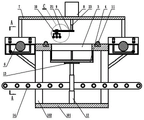
FIG. 2 is a front cross-sectional view of a plate cutting apparatus for pressure vessel production according to an embodiment of the present invention;
FIG. 3 is a cross-sectional view taken at A-A of FIG. 2;
FIG. 4 is an enlarged view of a portion of FIG. 3 at B;
fig. 5 is a perspective structural view of a conveying unit provided in an embodiment of the present invention;
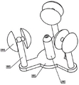
fig. 6 is a perspective structural view of a tray according to an embodiment of the present invention;
FIG. 7 is a perspective view of a cutting assembly according to an embodiment of the present invention;
FIG. 8 is an enlarged view of a portion of FIG. 2 at C;
in the drawings: 1-a frame; 101-a base; 102-a pillar; 2-processing the platform; 3-a material leaking hole; 4-carrying tray; 401-round bottom plate; 402-a gear lever; 5-a box base; 6-a conveying unit; 601-a rotating shaft; 602-a drive roller; 7-a mounting frame; 8-a driving member; 9-a transverse frame; 10-a cutting assembly; 1001-base; 1002-laser cutting head; 1003-extension pole; 1004 — a rolling member; 11-a rolling support; 12-a telescopic member; 13-a transverse plate; 14-a delivery assembly; 1401-a drive box; 1402-mounting plate; 1403-roller; 15-a scaffold; 16-a nip roll; 17-a regulating unit; 1701-lead screw; 18-a rod member; 19-a cassette; 20-an elastic member; 21-a control component; 2101-screw; 22-a card slot; 23-elastic telescopic rod.
Detailed Description
In order to make the objects, technical solutions and advantages of the present invention more apparent, the present invention is described in further detail below with reference to the accompanying drawings and embodiments. It should be understood that the specific embodiments described herein are merely illustrative of the invention and are not intended to limit the invention.
Specific implementations of the present invention are described in detail below with reference to specific embodiments.
As shown in fig. 1 and 2, a structure of a cutting apparatus for a pressure vessel production sheet according to an embodiment of the present invention includes:
frame 1, 1 top fixedly connected with processing platform 2 of frame still includes:
and the material leakage holes 3 are formed in the processing platform 2, and the diameter of each material leakage hole 3 is larger than the size of the cut plate.
The bearing disc 4 is arranged in the rack 1, the bearing disc 4 corresponds to the position of the material leakage hole 3, and the cut plate falls onto the bearing disc 4 through the material leakage hole 3.
The box bases 5 are fixedly connected to two sides of the processing platform 2, conveying units 6 are arranged in the box bases 5 on two sides, and the conveying units 6 are used for driving plates to transversely and horizontally move on the processing platform 2.
In an embodiment of the present invention, the device conveys the plates through the conveying units 6 on both sides, so that the plates can move laterally on the processing platform 2, and then the driving member 8 drives the cutting assembly 10 to perform the rotary cutting processing, and the cut circular plates can fall into the receiving tray 4 below through the material leaking holes 3 on the processing platform 2, the receiving tray 4 can receive a plurality of circular plates, and the circular plates can be conveniently moved to the subsequent processing device through the receiving tray 4.
In an example of the present invention, the conveying unit 6 may adopt a conveying belt disposed in the two side box seats 5, when the plate is placed in one side box seat 5, the side conveying unit 6 will convey the plate to the other side conveying unit 6, when the plate is on the processing platform 2, the conveying unit 6 can be controlled to stop working to facilitate the cutting process, and after the plate enters the other side conveying unit 6, the waste leftover material generated by cutting is discharged from the side conveying unit 6, the driving member 8 may adopt a motor, or of course a hydraulic motor, as long as the cutting assembly 10 on the cross frame 9 can be driven to rotate, the cutting assembly 10 may adopt a plasma cutting mode, the two sides of the material leaking hole 3 on the processing platform 2 are both provided with rolling supports 11, the rolling supports 11 may adopt a plurality of balls disposed on the processing platform 2, of course, the structural form of the roller can be adopted, the supporting effect can be mainly achieved, and the situation that the cutting size is not accurate due to deformation in the middle of the plate is avoided.
As shown in fig. 2, as a preferred embodiment of the present invention, the frame 1 includes a base 101 and four pillars 102, the pillars 102 are fixedly connected to the base 101, the processing platform 2 is fixedly connected to the tops of the pillars 102, an expansion member 12 is fixedly connected to the base 101, the other end of the expansion member 12 is fixedly connected to a horizontal plate 13, and the tray 4 is located on the horizontal plate 13.
In one aspect of this embodiment, the extensible member 12 may be an electric extensible rod, or a hydraulic extensible rod, the extensible member 12 may be used to raise the height of the receiving tray 4 to approach the material leaking port, so that there is not too large height difference during material dropping, and noise generated during material dropping of the circular plate is reduced, as shown in fig. 2 and 3, the horizontal conveying assemblies 14 are fixedly disposed on the pillars 102 at both sides, the conveying assemblies 14 are disposed at both sides of the extensible member 12, and a reserved space is disposed between the conveying assemblies 14 at both sides, the reserved space is larger than the diameter of the horizontal plate 13 and smaller than the diameter of the receiving tray 4, when the extensible member 12 is contracted and reset, the receiving tray 4 moves toward the base 101 until it is disposed on the conveying assemblies 14, based on the characteristic that the receiving tray 4 can perform lifting movement, the conveying assemblies 14 are disposed on the pillars 102 at both sides, after the receiving disc 4 is loaded with a specified number of round plates, the receiving disc 4 is reset through the telescopic piece 12 to be in contact with the conveying assembly 14, the conveying assembly 14 can transfer the receiving disc 4 to one side, a new receiving disc 4 can be added from the other side of the conveying assembly 14, the receiving disc 4 can be pushed upwards through the telescopic piece 12 to be in charge of receiving, and the quick discharging operation of the device is realized through the structure, as shown in fig. 6, the receiving disc 4 comprises a round bottom plate 401, a vertical stop lever 402 is fixedly connected to the outer side edge of the round bottom plate 401, the stop lever can limit the round plates falling onto the round bottom plate 401, as shown in fig. 5, the conveying assembly 14 comprises a driving box 1401 fixedly connected to the support column 102, a mounting plate 1402 is fixedly connected to the driving box 1401 towards the telescopic piece 12 side, a plurality of rollers 1403 in rotary connection are arranged on the mounting plate 1402 along the length direction of the mounting plate, the driving box 1401 is used for driving all the rollers 1403 to rotate synchronously and in the same direction, a belt transmission mechanism can be arranged inside the driving box 1401, a driving motor is fixedly arranged inside the driving box, the rollers 1403 can rotate synchronously, and the driving box 1401 can adopt a chain transmission structure.
As shown in fig. 3 and 4, as a preferred embodiment of the present invention, the conveying unit 6 may further include a rotating shaft 601 rotatably disposed in the box base 5, a driving roller 602 is fixedly connected to the rotating shaft 601, brackets 15 sliding along a length direction of the rotating shaft 601 are further disposed on two sides in the box base 5, clamping rollers 16 are disposed on the brackets 15, and an adjusting unit 17 is further disposed in the box base 5, and the adjusting unit 17 is configured to drive the brackets 15 on two sides to move relatively, so as to adjust a distance between the clamping rollers 16.
In one case of this embodiment, one end of the rotating shaft 601 is located outside the box base 5, the conveying units 6 of the box bases 5 on both sides can be connected by means of a belt or a chain, so as to enable the conveying units 6 on both sides to work synchronously, the adjusting unit 17 can adopt a screw 1701 transversely rotatably connected in the box base 5, the bracket 15 is fittingly sleeved on both ends of the screw 1701, both ends of the screw 1701 are of opposite thread structures, so that the distance between the clamping rollers 16 can be adjusted by rotating the screw 1701, transverse conveying of the plate can be ensured by rotating the driving roller 602, the clamping rollers 16 on both sides can ensure the alignment of the plate and can play a role of fixing the plate, avoiding the situation that the plate can shift to cause uneven cutting during cutting, of course, the adjusting unit 17 can adopt an electric telescopic rod arranged in the box base 5, the distance between the clamping rollers 16 can also be controlled, as shown in fig. 4, a rod member 18 sliding in the vertical direction is arranged on the support 15, the cross section of the rod member 18 is polygonal, clamping seats 19 for mounting the clamping rollers 16 are fixedly connected to two ends of the rod member 18, an elastic member 20 sleeved on the outer side of the rod member 18 is fixedly connected between the clamping seats 19 and the support 15, the elastic member 20 may be a spring, and certainly may also be an air bag structure, in an actual situation, if the clamping seats 19 and the support 15 are fixedly connected, the middle part of the plate may be separated from the driving roller 602 after the clamping rollers 16 clamp the plate from two sides due to the thickness of the plate, so that the conveying effect is lost, and therefore, the clamping rollers 16 are arranged to be capable of elastically and adjustably moving up and down, so that the clamped plate can be in contact with the driving roller 602.
As shown in fig. 2, as a preferred embodiment of the present invention, the cutting assembly 10 is laterally slidably connected to the cross frame 9, and the cross frame 9 is further provided with a control assembly 21, and the control assembly 21 is used for adjusting the position of the cutting assembly 10 on the cross frame 9.
In one case of this embodiment, as shown in fig. 8, a clamping groove 22 is formed in the cross frame 9, the cutting assembly 10 is slidably clamped in the clamping groove 22, the control assembly 21 includes a screw 2101 with a rotating wheel connected to the cross frame 9 and inserted into the cutting assembly 10 in a matching manner, and the position of the cutting assembly 10 can be adjusted by the screw 2101, so that the diameter of the cut circular plate can be adjusted, when the control assembly 21 can also adopt a form in which the cutting assembly 10 is driven by an air cylinder to move, the distance between the cutting assembly 10 and the plate is not limited in the foregoing, and the distance between the cutting assembly 10 and the plate is generally within a certain range by adopting plasma or laser cutting; in a further development of this embodiment, as shown in fig. 2 and 7, the output end of the driving member 8 is fixedly connected with the elastic telescopic rod 23, the cross frame 9 is fixedly connected to the other end of the elastic telescopic rod 23, the cutting assembly 10 includes a base 1001 disposed on the cross frame 9, a laser cutting head 1002 facing the processing platform 2 is disposed on the base 1001, an extension rod 1003 disposed outside the laser cutting head 1002 is rotatably connected to the base 1001, a rolling member 1004 is rotatably connected to the other end of the extension rod 1003, the rolling member 1004 may be in the form of a roller or a ball, when the plate moves, the rolling member 1004 is first in contact with the rolling member 1004, due to the curved structure of the outer surface of the rolling member 1004, the rolling member 1004 moves upwards, so as to ensure that the rolling member 1004 can move to the upper surface of the plate, and the length of the elastic telescopic rod 23 can be adjusted adaptively, therefore, by setting the length of the extension rod 1003, the laser cutting head 1002 can always keep a constant distance from the surface of the plate material, thereby ensuring the cutting uniformity and avoiding incomplete cutting caused by overlarge distance.
It will be evident to those skilled in the art that the invention is not limited to the details of the foregoing illustrative embodiments, and that the present invention may be embodied in other specific forms without departing from the spirit or essential attributes thereof. The present embodiments are therefore to be considered in all respects as illustrative and not restrictive, the scope of the invention being indicated by the appended claims rather than by the foregoing description, and all changes which come within the meaning and range of equivalency of the claims are therefore intended to be embraced therein. Any reference sign in a claim should not be construed as limiting the claim concerned.
Furthermore, it should be understood that although the present description refers to embodiments, not every embodiment may contain only a single embodiment, and such description is for clarity only, and those skilled in the art should integrate the description, and the embodiments may be combined as appropriate to form other embodiments understood by those skilled in the art.
Claims (9)
1. The utility model provides a panel cutting device is used in pressure vessel production, includes the frame, frame top fixedly connected with processing platform, its characterized in that still includes:
the material leakage holes are formed in the processing platform, and the diameter of each material leakage hole is larger than the size of the cut plate;
the bearing disc is arranged in the rack and corresponds to the position of the material leakage hole, and the cut plate falls onto the bearing disc through the material leakage hole;
the box seats are fixedly connected to two sides of the processing platform, conveying units are arranged in the box seats on the two sides and are used for driving the plates to transversely and horizontally move on the processing platform;
mounting bracket, mounting bracket fixed connection are on the case seat of both sides, fixedly connected with driving piece on the mounting bracket, and the output fixedly connected with crossbearer of driving piece is provided with the cutting assembly towards the processing platform side on the crossbearer.
2. The plate cutting device for producing the pressure vessel as claimed in claim 1, wherein the frame comprises a base and four pillars, the pillars are fixedly connected to the base, the processing platform is fixedly connected to the tops of the pillars, the base is fixedly connected with an extensible member, the other end of the extensible member is fixedly connected with a transverse plate, and the bearing plate is located on the transverse plate.
3. The plate cutting device for producing the pressure container as claimed in claim 2, wherein the pillars at two sides are fixedly provided with horizontal conveying assemblies, the conveying assemblies are located at two sides of the telescopic member, a reserved space is arranged between the conveying assemblies at two sides, the reserved space is larger than the diameter of the transverse plate and smaller than the diameter of the receiving disc, and when the telescopic member is contracted and reset, the receiving disc moves towards the base side until the receiving disc is located on the conveying assemblies.
4. The plate cutting device for producing the pressure container as claimed in claim 3, wherein the conveying assembly comprises a driving box body fixedly connected to the support, a mounting plate is fixedly connected to the driving box body towards the telescopic member, a plurality of rotatably connected rollers are arranged on the mounting plate along the length direction of the mounting plate, and the driving box body is used for driving all the rollers to rotate synchronously and in the same direction.
5. The plate cutting device for producing the pressure container according to claim 1, wherein the conveying unit comprises a rotating shaft rotatably disposed in the box base, a driving roller is fixedly connected to the rotating shaft, brackets sliding along the length direction of the rotating shaft are further disposed on two sides in the box base, clamping rollers are disposed on the brackets, and an adjusting unit is further disposed in the box base and used for driving the brackets on the two sides to move relatively, so as to adjust the distance between the clamping rollers.
6. The plate cutting device for producing the pressure vessel as claimed in claim 5, wherein the support is provided with a rod member sliding in a vertical direction, the cross section of the rod member is polygonal, two ends of the rod member are fixedly connected with clamping seats for mounting the clamping rollers, and an elastic member sleeved on the rod member at the outer side is fixedly connected between the clamping seats and the support.
7. The pressure vessel production panel cutting apparatus of claim 1, wherein the cutting assembly is laterally slidably connected to a cross frame, and a control assembly is further disposed on the cross frame, and the control assembly is configured to adjust a position of the cutting assembly on the cross frame.
8. The plate cutting device for producing the pressure container as claimed in claim 1, wherein the output end of the driving member is fixedly connected with an elastic telescopic rod, the cross frame is fixedly connected to the other end of the elastic telescopic rod, the cutting assembly comprises a base arranged on the cross frame, a laser cutting head facing the side of the processing platform is arranged on the base, an extension rod located on the outer side of the laser cutting head is rotatably connected to the base, and a rolling member is rotatably connected to the other end of the extension rod.
9. The plate cutting device for producing the pressure vessel as claimed in claim 1, wherein rolling support members are provided on both sides of the material leaking hole on the processing platform.
Priority Applications (1)
| Application Number | Priority Date | Filing Date | Title |
|---|---|---|---|
| CN202210795748.XA CN114871596B (en) | 2022-07-07 | 2022-07-07 | Plate cutting device for pressure container production |
Applications Claiming Priority (1)
| Application Number | Priority Date | Filing Date | Title |
|---|---|---|---|
| CN202210795748.XA CN114871596B (en) | 2022-07-07 | 2022-07-07 | Plate cutting device for pressure container production |
Publications (2)
| Publication Number | Publication Date |
|---|---|
| CN114871596A true CN114871596A (en) | 2022-08-09 |
| CN114871596B CN114871596B (en) | 2023-01-03 |
Family
ID=82682746
Family Applications (1)
| Application Number | Title | Priority Date | Filing Date |
|---|---|---|---|
| CN202210795748.XA Active CN114871596B (en) | 2022-07-07 | 2022-07-07 | Plate cutting device for pressure container production |
Country Status (1)
| Country | Link |
|---|---|
| CN (1) | CN114871596B (en) |
Cited By (1)
| Publication number | Priority date | Publication date | Assignee | Title |
|---|---|---|---|---|
| CN118218805A (en) * | 2024-05-27 | 2024-06-21 | 上海腾丞机械科技有限公司 | Cutting process for annular steel plate |
Citations (31)
| Publication number | Priority date | Publication date | Assignee | Title |
|---|---|---|---|---|
| CN205464547U (en) * | 2016-04-15 | 2016-08-17 | 广州市荣声智能家具有限公司 | Plate cutting device |
| CN206718052U (en) * | 2017-05-22 | 2017-12-08 | 杭州长庆汇科技有限公司 | A kind of plate cutting device |
| CN208099578U (en) * | 2018-02-24 | 2018-11-16 | 佛山智达思佳机电科技有限公司 | A kind of auto parts and components processing plate cutting machine plain circular cutting mechanism |
| CN109202312A (en) * | 2018-11-14 | 2019-01-15 | 佛山市宏石激光技术有限公司 | A kind of plate deviation correction mechanism and the laser cutting machine using the deviation correction mechanism |
| CN208644213U (en) * | 2018-07-19 | 2019-03-26 | 邯郸市邯钢附属企业公司 | A kind of cutting machine of automatic fly-cutting annular sheet metal |
| CN109607220A (en) * | 2018-11-15 | 2019-04-12 | 华南智能机器人创新研究院 | A kind of vision tray conveying line |
| CN208775847U (en) * | 2018-08-21 | 2019-04-23 | 武汉爱疆智能科技有限公司 | A kind of solar battery sorting machine feeding device |
| CN208811701U (en) * | 2018-10-18 | 2019-05-03 | 郑州栾信科技有限公司 | A kind of environment-friendly type building plate cutting device |
| CN208873747U (en) * | 2018-08-28 | 2019-05-17 | 秦皇岛博冠科技有限公司 | It is a kind of to draw the feeding conveying mechanism for splitting machine for solar battery sheet |
| CN109894752A (en) * | 2017-12-08 | 2019-06-18 | 宝钢工程技术集团有限公司 | Customize the simple processing line and its application method of special backing plate |
| CN110950031A (en) * | 2019-11-22 | 2020-04-03 | 苏州晟成光伏设备有限公司 | Battery piece conveying platform and technology thereof |
| CN111037643A (en) * | 2019-12-31 | 2020-04-21 | 苏州新派特信息科技有限公司 | Cutting equipment for circular plate |
| CN111302064A (en) * | 2020-04-08 | 2020-06-19 | 江阴德龙激光能源设备有限公司 | Accurate unloader of laser scribing machine |
| CN210853114U (en) * | 2019-09-27 | 2020-06-26 | 珠海市诺途智能技术有限公司 | Visual detection packaging machine |
| CN210848827U (en) * | 2019-07-15 | 2020-06-26 | 天津泰格瑞祥仪器设备有限公司 | Laser cutting machine |
| CN211219109U (en) * | 2019-12-22 | 2020-08-11 | 健泰(佛冈)五金电器有限公司 | Steel plate circle cutting device |
| CN211444458U (en) * | 2019-12-21 | 2020-09-08 | 佛山市佳圣达工贸有限公司 | Device for improving production safety performance of conveying belt |
| CN111725119A (en) * | 2020-07-01 | 2020-09-29 | 湖南艾科威智能装备有限公司 | Universal transmission device suitable for silicon wafer battery piece magazine |
| CN111994640A (en) * | 2020-10-30 | 2020-11-27 | 四川富美达微电子有限公司 | Semiconductor lead frame stamping forming product ejection of compact is folded and is received transfer device |
| CN212144992U (en) * | 2020-03-05 | 2020-12-15 | 东莞市原天环保科技有限公司 | PP panel laser cutting device |
| CN112454459A (en) * | 2020-10-29 | 2021-03-09 | 安徽朗验科技有限公司 | A nonmetal board guillootine for gasket processing |
| CN213003344U (en) * | 2020-08-21 | 2021-04-20 | 深圳市天泽光电有限公司 | Forehead temperature gun LCD display screen cutting device |
| CN213351611U (en) * | 2020-09-03 | 2021-06-04 | 怀来宝福鑫隆新型建材有限公司 | Cutting device is used in steel construction production and processing |
| CN112935368A (en) * | 2021-02-19 | 2021-06-11 | 王成 | Automobile parts sheet metal device |
| CN213440099U (en) * | 2020-10-16 | 2021-06-15 | 常州顺唯尔材料科技有限公司 | Automatic punching device for diffusion plate |
| CN213889025U (en) * | 2020-09-04 | 2021-08-06 | 江门市新会区佰德日用品有限公司 | Metal cutting device with fixing function |
| CN214640635U (en) * | 2021-05-10 | 2021-11-09 | 武汉佳鸿鑫金属制品制造有限公司 | Steel plate shearing machine |
| CN214981456U (en) * | 2021-08-06 | 2021-12-03 | 沈阳晓马挤塑板有限公司 | Automatic cutting and unloading mechanism for extruded sheet processing |
| CN215202378U (en) * | 2021-08-02 | 2021-12-17 | 宁波乐图纸制品有限公司 | Paper toy picture arrangement cutting device |
| CN114227006A (en) * | 2021-12-23 | 2022-03-25 | 深圳市万福昌科技有限公司 | Laser cutting equipment that multi-angle was adjusted |
| CN216656786U (en) * | 2022-01-10 | 2022-06-03 | 商丘市海顺机械设备有限公司 | Automatic go up laser cutting machine of unloading |
-
2022
- 2022-07-07 CN CN202210795748.XA patent/CN114871596B/en active Active
Patent Citations (31)
| Publication number | Priority date | Publication date | Assignee | Title |
|---|---|---|---|---|
| CN205464547U (en) * | 2016-04-15 | 2016-08-17 | 广州市荣声智能家具有限公司 | Plate cutting device |
| CN206718052U (en) * | 2017-05-22 | 2017-12-08 | 杭州长庆汇科技有限公司 | A kind of plate cutting device |
| CN109894752A (en) * | 2017-12-08 | 2019-06-18 | 宝钢工程技术集团有限公司 | Customize the simple processing line and its application method of special backing plate |
| CN208099578U (en) * | 2018-02-24 | 2018-11-16 | 佛山智达思佳机电科技有限公司 | A kind of auto parts and components processing plate cutting machine plain circular cutting mechanism |
| CN208644213U (en) * | 2018-07-19 | 2019-03-26 | 邯郸市邯钢附属企业公司 | A kind of cutting machine of automatic fly-cutting annular sheet metal |
| CN208775847U (en) * | 2018-08-21 | 2019-04-23 | 武汉爱疆智能科技有限公司 | A kind of solar battery sorting machine feeding device |
| CN208873747U (en) * | 2018-08-28 | 2019-05-17 | 秦皇岛博冠科技有限公司 | It is a kind of to draw the feeding conveying mechanism for splitting machine for solar battery sheet |
| CN208811701U (en) * | 2018-10-18 | 2019-05-03 | 郑州栾信科技有限公司 | A kind of environment-friendly type building plate cutting device |
| CN109202312A (en) * | 2018-11-14 | 2019-01-15 | 佛山市宏石激光技术有限公司 | A kind of plate deviation correction mechanism and the laser cutting machine using the deviation correction mechanism |
| CN109607220A (en) * | 2018-11-15 | 2019-04-12 | 华南智能机器人创新研究院 | A kind of vision tray conveying line |
| CN210848827U (en) * | 2019-07-15 | 2020-06-26 | 天津泰格瑞祥仪器设备有限公司 | Laser cutting machine |
| CN210853114U (en) * | 2019-09-27 | 2020-06-26 | 珠海市诺途智能技术有限公司 | Visual detection packaging machine |
| CN110950031A (en) * | 2019-11-22 | 2020-04-03 | 苏州晟成光伏设备有限公司 | Battery piece conveying platform and technology thereof |
| CN211444458U (en) * | 2019-12-21 | 2020-09-08 | 佛山市佳圣达工贸有限公司 | Device for improving production safety performance of conveying belt |
| CN211219109U (en) * | 2019-12-22 | 2020-08-11 | 健泰(佛冈)五金电器有限公司 | Steel plate circle cutting device |
| CN111037643A (en) * | 2019-12-31 | 2020-04-21 | 苏州新派特信息科技有限公司 | Cutting equipment for circular plate |
| CN212144992U (en) * | 2020-03-05 | 2020-12-15 | 东莞市原天环保科技有限公司 | PP panel laser cutting device |
| CN111302064A (en) * | 2020-04-08 | 2020-06-19 | 江阴德龙激光能源设备有限公司 | Accurate unloader of laser scribing machine |
| CN111725119A (en) * | 2020-07-01 | 2020-09-29 | 湖南艾科威智能装备有限公司 | Universal transmission device suitable for silicon wafer battery piece magazine |
| CN213003344U (en) * | 2020-08-21 | 2021-04-20 | 深圳市天泽光电有限公司 | Forehead temperature gun LCD display screen cutting device |
| CN213351611U (en) * | 2020-09-03 | 2021-06-04 | 怀来宝福鑫隆新型建材有限公司 | Cutting device is used in steel construction production and processing |
| CN213889025U (en) * | 2020-09-04 | 2021-08-06 | 江门市新会区佰德日用品有限公司 | Metal cutting device with fixing function |
| CN213440099U (en) * | 2020-10-16 | 2021-06-15 | 常州顺唯尔材料科技有限公司 | Automatic punching device for diffusion plate |
| CN112454459A (en) * | 2020-10-29 | 2021-03-09 | 安徽朗验科技有限公司 | A nonmetal board guillootine for gasket processing |
| CN111994640A (en) * | 2020-10-30 | 2020-11-27 | 四川富美达微电子有限公司 | Semiconductor lead frame stamping forming product ejection of compact is folded and is received transfer device |
| CN112935368A (en) * | 2021-02-19 | 2021-06-11 | 王成 | Automobile parts sheet metal device |
| CN214640635U (en) * | 2021-05-10 | 2021-11-09 | 武汉佳鸿鑫金属制品制造有限公司 | Steel plate shearing machine |
| CN215202378U (en) * | 2021-08-02 | 2021-12-17 | 宁波乐图纸制品有限公司 | Paper toy picture arrangement cutting device |
| CN214981456U (en) * | 2021-08-06 | 2021-12-03 | 沈阳晓马挤塑板有限公司 | Automatic cutting and unloading mechanism for extruded sheet processing |
| CN114227006A (en) * | 2021-12-23 | 2022-03-25 | 深圳市万福昌科技有限公司 | Laser cutting equipment that multi-angle was adjusted |
| CN216656786U (en) * | 2022-01-10 | 2022-06-03 | 商丘市海顺机械设备有限公司 | Automatic go up laser cutting machine of unloading |
Cited By (2)
| Publication number | Priority date | Publication date | Assignee | Title |
|---|---|---|---|---|
| CN118218805A (en) * | 2024-05-27 | 2024-06-21 | 上海腾丞机械科技有限公司 | Cutting process for annular steel plate |
| CN118218805B (en) * | 2024-05-27 | 2024-09-06 | 上海腾丞机械科技有限公司 | Cutting process for annular steel plate |
Also Published As
| Publication number | Publication date |
|---|---|
| CN114871596B (en) | 2023-01-03 |
Similar Documents
| Publication | Publication Date | Title |
|---|---|---|
| CN114871596B (en) | Plate cutting device for pressure container production | |
| CN213592162U (en) | Hydraulic horizontal moving type roller frame | |
| CN110405103A (en) | A kind of brake disc production line | |
| CN110771950B (en) | Cigarette explodes pearl and loads equipment | |
| CN216444566U (en) | Centering clamping mechanism and glass panel turnover machine thereof | |
| CN209452612U (en) | A kind of outcase of refrigerator flexible production line | |
| CN111252488B (en) | Precision manipulator handling system | |
| CN114310004A (en) | Irregular material fixing structure for laser marking machine | |
| CN112354736A (en) | Plate gluing device | |
| CN203754043U (en) | Faceplate turnover device | |
| CN209160127U (en) | A kind of adjustable cardboard carriage of width | |
| CN209973699U (en) | Cell-phone screen material loading machine | |
| CN117181874A (en) | Water tank stamping cover plate edge folding device | |
| CN215285582U (en) | Mattress rotary folding machine | |
| CN214568204U (en) | Automatic unloader of plastics tubular product | |
| CN210854212U (en) | Partially-pasting equipment discharging mechanism | |
| CN211110134U (en) | Liftable two roller aluminized film rolling machines of adjusting | |
| CN208787666U (en) | Feeding device is used in a kind of processing of section roll end face | |
| CN216324350U (en) | Bending machine for producing storage racks | |
| CN220481262U (en) | Metal plate polishing equipment | |
| CN221518961U (en) | Novel anticollision material processing former | |
| CN115067086B (en) | Baling device of baling machine | |
| CN116885048B (en) | Solar cell on-line loading and unloading equipment | |
| CN218808393U (en) | Conveying device for welding processing of steel structural part | |
| CN213324376U (en) | Flour bag packing transfer equipment |
Legal Events
| Date | Code | Title | Description |
|---|---|---|---|
| PB01 | Publication | ||
| PB01 | Publication | ||
| SE01 | Entry into force of request for substantive examination | ||
| SE01 | Entry into force of request for substantive examination | ||
| GR01 | Patent grant | ||
| GR01 | Patent grant |