CN114769869A - Laser welding machine for machining mobile phone parts - Google Patents
Laser welding machine for machining mobile phone parts Download PDFInfo
- Publication number
- CN114769869A CN114769869A CN202210660756.3A CN202210660756A CN114769869A CN 114769869 A CN114769869 A CN 114769869A CN 202210660756 A CN202210660756 A CN 202210660756A CN 114769869 A CN114769869 A CN 114769869A
- Authority
- CN
- China
- Prior art keywords
- annealing
- sliding
- rod
- mobile phone
- welding
- Prior art date
- Legal status (The legal status is an assumption and is not a legal conclusion. Google has not performed a legal analysis and makes no representation as to the accuracy of the status listed.)
- Pending
Links
- 238000003466 welding Methods 0.000 title claims abstract description 63
- 238000003754 machining Methods 0.000 title claims description 7
- 238000000137 annealing Methods 0.000 claims abstract description 62
- 230000001681 protective effect Effects 0.000 claims abstract description 23
- 238000001514 detection method Methods 0.000 claims abstract description 21
- 230000005540 biological transmission Effects 0.000 claims abstract description 7
- 239000000523 sample Substances 0.000 claims abstract description 7
- 230000001360 synchronised effect Effects 0.000 claims abstract description 3
- 238000001179 sorption measurement Methods 0.000 claims description 14
- 230000000694 effects Effects 0.000 claims description 2
- 238000004064 recycling Methods 0.000 claims 1
- 238000000034 method Methods 0.000 abstract description 6
- 235000014676 Phragmites communis Nutrition 0.000 description 8
- 239000000463 material Substances 0.000 description 6
- 229910000838 Al alloy Inorganic materials 0.000 description 5
- 238000003860 storage Methods 0.000 description 5
- 238000009960 carding Methods 0.000 description 2
- 230000007547 defect Effects 0.000 description 2
- 238000003825 pressing Methods 0.000 description 2
- 230000009286 beneficial effect Effects 0.000 description 1
- 230000002950 deficient Effects 0.000 description 1
- 238000009826 distribution Methods 0.000 description 1
- 238000010438 heat treatment Methods 0.000 description 1
- 238000004519 manufacturing process Methods 0.000 description 1
- 238000011084 recovery Methods 0.000 description 1
- 238000002310 reflectometry Methods 0.000 description 1
- 238000007711 solidification Methods 0.000 description 1
- 230000008023 solidification Effects 0.000 description 1
- 210000003437 trachea Anatomy 0.000 description 1
Images


Classifications
-
- B—PERFORMING OPERATIONS; TRANSPORTING
- B23—MACHINE TOOLS; METAL-WORKING NOT OTHERWISE PROVIDED FOR
- B23K—SOLDERING OR UNSOLDERING; WELDING; CLADDING OR PLATING BY SOLDERING OR WELDING; CUTTING BY APPLYING HEAT LOCALLY, e.g. FLAME CUTTING; WORKING BY LASER BEAM
- B23K26/00—Working by laser beam, e.g. welding, cutting or boring
- B23K26/20—Bonding
- B23K26/21—Bonding by welding
-
- B—PERFORMING OPERATIONS; TRANSPORTING
- B23—MACHINE TOOLS; METAL-WORKING NOT OTHERWISE PROVIDED FOR
- B23K—SOLDERING OR UNSOLDERING; WELDING; CLADDING OR PLATING BY SOLDERING OR WELDING; CUTTING BY APPLYING HEAT LOCALLY, e.g. FLAME CUTTING; WORKING BY LASER BEAM
- B23K26/00—Working by laser beam, e.g. welding, cutting or boring
- B23K26/70—Auxiliary operations or equipment
- B23K26/702—Auxiliary equipment
Landscapes
- Engineering & Computer Science (AREA)
- Physics & Mathematics (AREA)
- Optics & Photonics (AREA)
- Plasma & Fusion (AREA)
- Mechanical Engineering (AREA)
- Heat Treatment Of Articles (AREA)
Abstract
The invention discloses a laser welding machine for processing mobile phone parts, which relates to the technical field of mobile phone processing, and comprises a welding assembly, a shielding gas assembly, an annealing assembly, a moving assembly and a transmission belt assembly, wherein the welding assembly also comprises a sliding rod arranged on a turntable fixing support in a sliding manner, and the sliding of the sliding rod is realized by the synchronous rotation of a large turntable roller and a sliding rod cam; one end of the sliding rod is fixedly provided with a welding platform, a touch rod is rotatably arranged on the welding platform, and a detection connecting rod is fixedly arranged on the touch rod and used for leveling a detection probe to realize detection; the protective gas component is used for connecting protective gas during welding, and the annealing component realizes annealing treatment on the welded parts; the equipment solves the problems that protective gas is communicated and an annealing process is added during welding, and is provided with detection equipment and an unqualified product classification device; unqualified products are greatly reduced, and the welding efficiency is improved.
Description
Technical Field
The invention relates to the technical field of mobile phone processing, in particular to a laser welding machine for processing mobile phone parts.
Background
The cell-phone medium plate all adopts aluminum alloy frame and aluminum alloy medium plate to weld. Laser welding uses laser as a high-energy density light source, and is characterized in that a heating block and instantaneous solidification are adopted, and the aspect ratio is as high as 12: 1, the aluminum alloy door and window can be welded through the laser welding without large heat influence on the surface. But some defect problems inevitably occur during welding due to the high reflectivity and good thermal conductivity of the aluminum alloy itself and the shielding effect of plasma, wherein the two most important defects are air holes and thermal cracks. One of the major drawbacks of laser welding of aluminum alloys is the problem of blowholes. Through tests, the generation of air holes is mainly influenced by factors such as the surface state of a material, the type and flow of protective gas, a protection method, welding energy, the shape of a welding seam and the like, the generation of the air holes can be reduced to the minimum when the gas protection is enhanced and welding with high power, high speed and large defocusing amount (negative value) is adopted, an annealing process is adopted after welding, the generation of cracks can be effectively reduced, and most of the prior art does not adopt gas protection when welding and annealing treatment after welding, so that a plurality of air holes and hot cracks exist, and the product quality is seriously influenced.
The Chinese patent with publication number CN106735899A discloses an automatic spot welding machine, which is used for welding a reed carried by a reed on a rear shell of a mobile phone and comprises a workbench, a material distributing mechanism, a conveying mechanism, a rotating mechanism and a laser welding machine; the conveying mechanism comprises a supporting frame, a conveying track and a material sucking device; the first conveying cylinder is arranged on the conveying track and pushes the material sucking device to transversely slide on the conveying track; the material suction device is provided with a second conveying cylinder and a suction piece; the suction piece is provided with a suction nozzle for sucking the reed. The automatic spot welding machine is provided with the carding track through the material distribution mechanism, carding the reed carrying belt, sucking the reed to the rear shell of the mobile phone through the conveying track, and then pressing the reed by the reed pressing head so as to facilitate welding of the laser welding machine, the whole process is controlled by the control system, automatic production is realized, the whole equipment can be operated by one person, and the labor intensity of workers is greatly reduced. The equipment improves the welding efficiency of the reed but fails to solve the phenomena of hot crack and air hole which are possibly caused by welding; and detection of welded products and classification of defective products.
Disclosure of Invention
Aiming at the technical problems, the invention solves the problems of adding protective gas and annealing process during welding, and is provided with detection equipment and an unqualified product classification device; greatly reducing the technical problem of unqualified products.
The technical scheme adopted by the invention is as follows: the utility model provides a laser welder for cell-phone parts machining, includes welding subassembly, shielding gas subassembly, annealing subassembly, removal subassembly, transmission band subassembly, its characterized in that: the welding assembly further comprises a sliding rod which is arranged on the turntable fixing support in a sliding mode, and the sliding of the sliding rod is realized by synchronous rotation of a large turntable roller and a sliding rod cam; a welding platform is fixedly arranged at one end of the sliding rod, a limiting frame is fixedly arranged on the welding platform, a touch rod is rotatably arranged on the welding platform, and a detection connecting rod is also fixedly arranged on the touch rod and used for leveling a detection probe; one end of the welding platform is slidably provided with a jacking rod, and the jacking rod is movably connected with the trapezoidal sliding block and used for transferring mobile phone parts; one end of the trapezoidal sliding block is provided with a plurality of groups of symmetrically distributed transverse sliding rollers in a sliding manner, one side of each transverse sliding roller is fixedly provided with a plurality of groups of symmetrically distributed sliding frames, each sliding frame is arranged on the T-shaped transverse guide rail in a sliding manner, one side of each sliding frame is also fixedly provided with a first touch round rod and a second touch round rod, and the first touch round rods are movably matched with the lifting rotating frame to transfer the mobile phone parts on the conveying belt assembly into a plurality of groups of symmetrically distributed clamps for welding; the other end of the lifting rotating frame is movably connected with a lifting rotating column, a lifting adsorption plate and a lifting gear are fixedly arranged on the lifting rotating column, the lifting gear is in rotating fit with the lifting rack, the lifting rotating column is arranged in the first moving support in a sliding mode, a cylinder assembly is further fixedly arranged on the second moving support, and the cylinder assembly is used for separating unqualified products into a recovery box.
Further, the one end of moving movable support two is the fixed annealing subassembly that is provided with still, annealing subassembly is still including fixed setting annealing dish on annealing support, it is provided with annealing carousel still to move about on the annealing support, the fixed adsorption plate that is provided with on the annealing carousel, the fixed annealing carriage that is provided with of one end of annealing carousel, the annealing carriage slides and sets up on annealing support.
Further, carousel gyro wheel and carousel clearance fit, the carousel outside is rotated and is provided with small turntable two and small turntable one, rotate on the small turntable one and be connected with the protective gas connecting rod, the protective gas connecting rod rotates the one end that sets up at the piston rod, the fixed piston that is provided with of the other end of piston rod, the piston slides and sets up in the blast pipe, and the other end of blast pipe is fixed and is provided with the protective gas holding vessel.
Further, a turning cylinder is fixedly arranged at one end of the second moving support, a limiting rod is fixedly arranged on the second moving support, a placing table is arranged at the other end of the turning cylinder in a rotating mode, a turning column and a turning spring frame are fixedly arranged on one side of the second moving support, and a tensioning spring is movably arranged on the turning spring frame.
Furthermore, one side of the T-shaped transverse guide rail is movably provided with a return spring, and one side of the T-shaped longitudinal guide rail is movably provided with a return spring.
Furthermore, the lifting rack is fixedly arranged on a second movable support, and one end of the second movable support is rotatably provided with a transmission belt assembly.
Furthermore, the lifting rotating frame is rotatably arranged on the first moving support, a sliding groove is formed in one side of the lifting rotating frame, the first moving support is provided with the sliding groove, and the first moving support and the lifting rotating frame are symmetrically distributed in multiple groups.
Furthermore, a plurality of cylinders are fixedly arranged on the annealing support, and a plurality of sliding grooves used for being matched with the cylinders to realize overturning are formed in the annealing turntable.
Compared with the prior art, the invention has the beneficial effects that: protective gas is communicated during welding to reduce the phenomenon of air holes of the product; the annealing process is added, the frequency of hot cracks of the product is reduced, the detection equipment is arranged, the outflow of unqualified products is reduced, the unqualified product classification device is additionally arranged, the labor cost is greatly reduced, and the product processing efficiency is improved.
Drawings
Fig. 1 is a schematic view of the overall structure of the present invention.
FIG. 2 is a schematic view of a welded assembly according to the present invention.
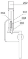
FIG. 3 is a schematic view of a shielding gas assembly according to the present invention.
FIG. 4 is a schematic view of an annealing assembly according to the present invention.
FIG. 5 is a schematic view of a moving assembly according to the present invention.
FIG. 6 is a schematic view of the structure of the flip-up assembly of the mobile assembly of the present invention.
Reference numerals: 1-welding the assembly; 2-a shielding gas component; 3-annealing the component; 4-a moving assembly; 5-a conveyor belt assembly; 101-large turntable; 102-small turntable I; 103-a slide bar; 104-a welding platform; 105-large turntable roller; 106-slide bar cam; 107-turntable fixing support; 108-small turntable II; 109-a jack rod; 110-a touch lever; 111-a limiting frame; 112-detection link; 113-a detection probe; 114-the trachea; 115-a welding head; 201-shielding gas bracket; 202-protective gas storage tank; 203-exhaust pipe; 204-a piston rod; 205-shielding gas linkage; 301-an adsorption plate; 302-annealing plate; 303-annealing carriage; 304-an annealing turntable; 305-annealing the scaffold; 401-moving the first support; 402-lifting the rotating column; 403-lifting the turret; 404-moving the second support; 405-lifting the adsorption plate; 406-a lifting gear; 407-lifting rack; 408-T-shaped cross-rails; 409-a carriage; 410-T-shaped longitudinal rails; 411-touch round bar one; 412-trapezoidal slider; 413-guide post; 414-lateral sliding rollers; 415-touching the round bar II; 416-a clamp; 420-overturning the cylinder; 421-a limiting rod; 422-placing table; 423-turning column; 424-Turn over the spring holder.
Detailed Description
The technical solutions in the embodiments of the present invention will be clearly and completely described below with reference to the drawings in the embodiments of the present invention, and it is obvious that the described embodiments are only a part of the embodiments of the present invention, and not all of the embodiments. All other embodiments, which can be derived by a person skilled in the art from the embodiments given herein without making any creative effort, shall fall within the protection scope of the present invention.
As shown in fig. 1, fig. 2, fig. 3, fig. 4, fig. 5, and fig. 6, a laser welder for mobile phone part processing includes a welding assembly 1, a shielding gas assembly 2, an annealing assembly 3, a moving assembly 4, and a transmission belt assembly 5, where the welding assembly 1 includes a large turntable 101 rotatably disposed on a turntable fixing support 107, the large turntable 101 is provided with a plurality of sliding slots, the outside of the large turntable 101 is provided with a plurality of small rollers for spacing-supporting the large turntable 101 and transmitting the power of the large turntable 101, a sliding rod cam 106 and a large turntable roller 105 rotate synchronously, so that a sliding rod 103 slides in the turntable fixing support 107, one side of a small turntable 108 is rotatably provided with a shielding gas connecting rod 205, one side of the shielding gas connecting rod 205 is rotatably provided with a piston rod 204, the small turntable 108 rotates to pull the piston rod 204 to slide in the sliding slot, and pulls a piston fixedly disposed at one end of the piston rod 204 to one end of an exhaust pipe 203, the shielding gas within the shielding gas storage tank 202 is released into the welding head 115.
A welding platform 104 is fixedly arranged at one end of the sliding rod 103, a limiting frame 111 is fixedly arranged on the welding platform 104, the limiting frame 111 is used for limiting the rotating position of the touch rod 110, a detection connecting rod 112 is fixedly arranged on the touch rod 110, a detection probe 113 is rotatably arranged at one end of the detection connecting rod 112, an air pipe 114 is fixedly arranged on the welding platform 104, a welding head 115 is fixedly arranged on the inner side of the air pipe 114, and a jacking rod 109 is also slidably arranged on the welding platform 104 and used for touching the trapezoidal sliding block 412; the trapezoidal sliding block 412 slides on a plurality of guide posts 413 which are symmetrically arranged, a transverse sliding roller 414 is arranged on one side of the trapezoidal sliding block 412 in a sliding mode, the transverse sliding rollers 414 are distributed in a plurality of groups symmetrically, a T-shaped longitudinal guide rail 410 is fixedly arranged on the transverse sliding roller 414, a sliding frame 409 is arranged on the T-shaped longitudinal guide rail 410 in a sliding mode, the sliding frame 409 is arranged on the T-shaped transverse guide rail 408 in a sliding mode, the T-shaped longitudinal guide rail 410 is arranged on the second moving support 404 in a sliding mode, the T-shaped transverse guide rail 408 is arranged on the second moving support 404 in a sliding mode, and return springs are arranged on the T-shaped longitudinal guide rail 410 and the T-shaped transverse guide rail 408.
A second touch round rod 415 and a first touch round rod 411 are fixedly arranged on the sliding frame 409, the first touch round rod 411 is used for touching one end of the lifting rotating frame 403 to enable the lifting rotating frame 403 to rotate to a specified position, and further the lifting adsorption plate 405 and the lifting gear 406 which are fixedly connected to the lifting rotating column 402 are lifted to the specified position, and a plurality of symmetrically distributed clamps 416 are fixedly arranged on the sliding frame 409 and used for clamping mobile phone parts; the first movable support 401 is fixedly arranged on the second movable support 404; the second moving support 404 is further fixedly provided with a turning cylinder 420, the second moving support 404 is fixedly provided with a limiting rod 421, the turning cylinder 420 is rotatably provided with a placing table 422, the placing table 422 is provided with a spring, one end of the spring is movably mounted on a turning spring frame 424, the turning spring frame 424 is fixedly mounted on the second moving support 404, a turning column 423 is fixedly mounted below one side of the placing table 422, and the turning column 423 is fixedly mounted on the second moving support 404.
One end of the second movable support 404 is further fixedly provided with an annealing assembly 3, the annealing assembly 3 further comprises an annealing disc 302 fixedly arranged on the annealing support 305, an annealing turntable 304 is movably arranged on the annealing support 305, an adsorption plate 301 is fixedly arranged on the annealing turntable 304, one end of the annealing turntable 304 is fixedly provided with an annealing sliding frame 303, and the annealing sliding frame 303 is slidably arranged on the annealing support 305. The outer side of the large turntable 101 is rotatably provided with a small turntable II 108 and a small turntable I102, the small turntable I102 is rotatably connected with a protective gas connecting rod 205, the protective gas connecting rod 205 is rotatably arranged at one end of a piston rod 204, the other end of the piston rod 204 is fixedly provided with a piston, the piston is slidably arranged in an exhaust pipe 203, the other end of the exhaust pipe 203 is fixedly provided with a protective gas storage tank 202, the protective gas storage tank 202 is connected with the exhaust pipe 203 through a pipeline, and a protective gas support 201 is fixedly arranged on a movable support II 404.
The invention discloses a laser welding machine for processing mobile phone parts, which has the working principle that: the sliding rod cam 106 is coaxially and fixedly connected with the large turntable roller 105, one end of the sliding rod cam 106 is fixedly connected to an output shaft of a motor, the motor rotates anticlockwise to a preset position, at the moment, the large turntable roller 105 rotates anticlockwise to be matched with a sliding groove on the large turntable 101 to drive the large turntable 101 to rotate to the preset position, at the moment, the sliding rod 103 is separated from the sliding groove, at the moment, the sliding rod 103 slides to the preset position towards the welding head 115 in the turntable fixing support 107, at the moment, the ejector rod 109 touches the trapezoidal sliding block 412, the trapezoidal sliding block 412 slides to the preset position along the guide pillar 413, at the moment, the symmetrically arranged transverse sliding rollers 414 drive the T-shaped longitudinal guide rail 410 to be opened outwards to the preset position, when the touch rod 110 is tightly clamped in the limiting frame 111, at the moment, the detection connecting rod 112 pulls one end of the detection probe 113 to enable the detection probe 113 to be parallel to a mobile phone part for detection, when an unqualified product is detected, upset cylinder 420 contracts, and the drive is placed platform 422 and is descended, places platform 422 and gag lever post 421 sliding fit and restricts and places platform 422 rotational position, when placing platform 422 and the touching of upset post 423, places platform 422 anticlockwise rotation and will place the unqualified part on the platform 422 and transfer to the collecting box in.
When the touch rod 110 is clamped in the limiting frame 111, the touch rod 110 touches the second touch rod 415, so that the multiple groups of clamps 416 fixedly connected to the second touch rod 415 slide to preset positions in the direction of the trapezoidal sliding block 412, at the moment, the first touch rod 411 touches one end of the lifting rotating frame 403, the lifting rotating frame 403 rotates clockwise, the lifting rotating column 402 is driven to move in the direction of the second touch rod 415, and at the moment, the mobile phone part adsorbed on the lifting adsorption plate 405 is meshed with the lifting rack 407 fixedly arranged through the lifting gear 406, so that the lifting adsorption plate 405 rotates the welding assembly 180 degrees to transport the part to the position where the clamps 416 can be clamped.
When the large turntable roller 105 drives the large turntable 101 to rotate, the large turntable 101 drives the small turntable two 108 to rotate, the small turntable two 108 is eccentrically connected with a protective gas connecting rod 205, the protective gas connecting rod 205 pulls the piston rod 204 to slide in the chute so as to drive the piston on the piston rod 204, the exhaust pipe 203 is communicated with a pipeline connected with the protective gas storage tank 202, and protective gas is released.
When the welding platform 104 is pressed down, the welding head 115 starts to weld, the gas pipe 114 starts to release the protective gas, the clamp 416 is separated outwards, the mobile phone parts on the placing platforms 422 are separated, the lifting adsorption plate 405 conveys the mobile phone parts on the conveyor belt assembly 5 to the preset position, when the welding platform 104 is lifted, the jacking rod 109 is separated from the trapezoidal sliding block 412 firstly, the clamp 416 clamps the mobile phone parts on the lifting adsorption plate 405 at the moment, and when the touch rod 110 is separated from the touch round rod II 415, the clamp 416 conveys the clamped parts to the placing platforms 422. The welding platform 104 sequentially descends and ascends to perform a reciprocating cycle, so that clamping, conveying and welding of the mobile phone parts, connection of protective gas and detection of the mobile phone parts are realized. The large turntable 101 drives the small turntable I102 to rotate while rotating, the small turntable I102 enables the annealing sliding frame 303 to slide on the annealing support 305 through a belt, the adsorption plate 301 adsorbs the mobile phone, when the annealing sliding frame 303 slides upwards, the annealing turntable 304 is driven to slide upwards, a sliding groove in the annealing turntable 304 is matched with a cylinder in the annealing support 305, the adsorption plate 301 is turned to a preset position below the annealing disc 302, and annealing treatment of mobile phone parts is carried out.
It will be evident to those skilled in the art that the invention is not limited to the details of the foregoing illustrative embodiments, and that the present invention may be embodied in other specific forms without departing from the spirit or essential attributes thereof. The present embodiments are therefore to be considered in all respects as illustrative and not restrictive, the scope of the invention being indicated by the appended claims rather than by the foregoing description, and all changes which come within the meaning and range of equivalency of the claims are therefore intended to be embraced therein, and any reference signs in the claims are not to be construed as limiting the scope of the claims.
Claims (8)
1. The utility model provides a laser welder for cell-phone parts machining, includes welding subassembly (1), shielding gas subassembly (2), annealing subassembly (3), removes subassembly (4), transmission band subassembly (5), its characterized in that: the welding assembly (1) comprises a sliding rod (103) which is arranged on a rotary table fixing support (107) in a sliding mode, and the sliding of the sliding rod (103) is realized by synchronous rotation of a large rotary table roller (105) and a sliding rod cam (106); a welding platform (104) is fixedly arranged at one end of the sliding rod (103), a limiting frame (111) is fixedly arranged on the welding platform (104), a touch rod (110) is rotatably arranged on the welding platform (104), and a detection connecting rod (112) is further fixedly arranged on the touch rod (110) and used for leveling a detection probe (113); one end of the welding platform (104) is slidably provided with a jacking rod (109), and the jacking rod (109) is movably connected with the trapezoidal sliding block (412) and used for transferring mobile phone parts; one end of the trapezoidal sliding block (412) is provided with a plurality of groups of symmetrically distributed transverse sliding rollers (414) in a sliding manner, one side of each transverse sliding roller (414) is fixedly provided with a plurality of groups of symmetrically distributed sliding frames (409), each sliding frame (409) is arranged on the corresponding T-shaped transverse guide rail (408) in a sliding manner, one side of each sliding frame (409) is also fixedly provided with a first touch rod (411) and a second touch rod (415), and the first touch rod (411) is movably matched with the lifting rotating frame (403) and used for transferring mobile phone parts on the transmission belt assembly (5) into a plurality of groups of symmetrically distributed clamps (416) to be welded; the other end of the lifting rotating frame (403) is movably connected with a lifting rotating column (402), a lifting adsorption plate (405) and a lifting gear (406) are fixedly arranged on the lifting rotating column (402), the lifting gear (406) is in rotating fit with a lifting rack (407), the lifting rotating column (402) is arranged in the first moving support (401) in a sliding mode, and a cylinder assembly is fixedly arranged on the second moving support (404) and used for separating unqualified products into a recycling box.
2. The laser welder for mobile phone parts machining according to claim 1, characterized in that: the fixed one end that sets up at removal support two (404) of annealing subassembly (3), annealing subassembly (3) is including fixed annealing dish (302) that sets up on annealing support (305), it is provided with annealing carousel (304) still to move about on annealing support (305), the fixed adsorption plate (301) that is provided with on annealing carousel (304), the fixed annealing carriage (303) that is provided with in one end of annealing carousel (304), annealing carriage (303) slide and set up on annealing support (305).
3. The laser welder for mobile phone part processing as claimed in claim 1, wherein: big carousel gyro wheel (105) and big carousel (101) clearance fit, big carousel (101) outside is rotated and is provided with small turntable two (108) and small turntable one (102), it is connected with protective gas connecting rod (205) to rotate on small turntable one (102), protective gas connecting rod (205) are rotated and are set up the one end in piston rod (204), the fixed piston that is provided with of the other end of piston rod (204), piston rod (204) slide and set up in blast pipe (203), the fixed protective gas holding vessel (202) that is provided with of the other end of blast pipe (203).
4. The laser welder for mobile phone parts machining according to claim 1, characterized in that: the fixed upset cylinder (420) that is provided with of one end of moving bracket two (404), still fixed gag lever post (421) that is provided with on moving bracket two (404), the other end of upset cylinder (420) rotates and is provided with places platform (422), one side of moving bracket two (404) is fixed and is provided with upset post (423) and upset spring bracket (424), the activity is provided with taut spring on upset spring bracket (424).
5. The laser welder for mobile phone part processing as claimed in claim 1, wherein: one side of the T-shaped transverse guide rail (408) is movably provided with a return spring, and the T-shaped longitudinal guide rail (410) is movably provided with a return spring.
6. The laser welder for mobile phone part processing as claimed in claim 1, wherein: the lifting rack (407) is fixedly arranged on the second movable support (404), and one end of the second movable support (404) is rotatably provided with a transmission belt assembly (5).
7. The laser welder for mobile phone part processing as claimed in claim 1, wherein: the lifting rotating frame (403) is rotatably arranged on the first movable support (401), a sliding groove is formed in one side of the lifting rotating frame (403), the first movable support (401) is provided with the sliding groove, and the first movable support (401) and the lifting rotating frame (403) are symmetrically distributed in multiple groups.
8. The laser welder for mobile phone parts machining according to claim 2, characterized in that: a plurality of cylinders are fixedly arranged on the annealing support (305), and a plurality of sliding grooves are formed in the annealing turntable (304) and are used for being matched with the cylinders to realize overturning.
Priority Applications (1)
| Application Number | Priority Date | Filing Date | Title |
|---|---|---|---|
| CN202210660756.3A CN114769869A (en) | 2022-06-13 | 2022-06-13 | Laser welding machine for machining mobile phone parts |
Applications Claiming Priority (1)
| Application Number | Priority Date | Filing Date | Title |
|---|---|---|---|
| CN202210660756.3A CN114769869A (en) | 2022-06-13 | 2022-06-13 | Laser welding machine for machining mobile phone parts |
Publications (1)
| Publication Number | Publication Date |
|---|---|
| CN114769869A true CN114769869A (en) | 2022-07-22 |
Family
ID=82422051
Family Applications (1)
| Application Number | Title | Priority Date | Filing Date |
|---|---|---|---|
| CN202210660756.3A Pending CN114769869A (en) | 2022-06-13 | 2022-06-13 | Laser welding machine for machining mobile phone parts |
Country Status (1)
| Country | Link |
|---|---|
| CN (1) | CN114769869A (en) |
Cited By (1)
| Publication number | Priority date | Publication date | Assignee | Title |
|---|---|---|---|---|
| CN115351544A (en) * | 2022-09-15 | 2022-11-18 | 南通皋鑫科技开发有限公司 | SMD diode production pin welding set |
Citations (24)
| Publication number | Priority date | Publication date | Assignee | Title |
|---|---|---|---|---|
| US6031199A (en) * | 1997-10-28 | 2000-02-29 | Worthington Machine Technology | Combination laser cutting and blank welding apparatus and method |
| US6411470B1 (en) * | 1991-10-28 | 2002-06-25 | Censtor Corporation | Durable, low-vibration, dynamic-contact hard disk drive system |
| JP2004249307A (en) * | 2003-02-19 | 2004-09-09 | Akihisa Murata | Continuous automatic welding equipment for single-tube |
| CN102528353A (en) * | 2012-02-29 | 2012-07-04 | 黄一淼 | Full-automatic multi-station welding system |
| WO2014126172A1 (en) * | 2013-02-15 | 2014-08-21 | 日産自動車株式会社 | Laser welding method, laser welding device, and welded member |
| JP2015202505A (en) * | 2014-04-14 | 2015-11-16 | 株式会社アマダミヤチ | Tig welding method and tig welding device |
| CN106041304A (en) * | 2016-06-29 | 2016-10-26 | 宿州市冠星金属制品制造有限公司 | Laser welding system of multistation steel bands |
| CN106392318A (en) * | 2016-12-02 | 2017-02-15 | 长春理工大学 | Clutch driven disc-transmission disc structural part automatic preheating and clamping device and laser welding method |
| CN106735899A (en) * | 2016-12-14 | 2017-05-31 | 广东天机工业智能系统有限公司 | Stitch welding machine |
| CN108687443A (en) * | 2018-05-28 | 2018-10-23 | 宁波沪荣汽车部件有限公司 | A kind of laser assembly solder clamping and positioning device |
| CN109108419A (en) * | 2018-07-18 | 2019-01-01 | 苏州菲丽丝智能科技有限公司 | Copper pipe robot welding system and method |
| CN109623177A (en) * | 2019-01-11 | 2019-04-16 | 宁波宏志机器人科技有限公司 | A kind of robotic laser weldering downhand welding overhead welding integrated clamp with metal plate orthopaedic function |
| CN110369872A (en) * | 2019-08-15 | 2019-10-25 | 武汉宝悍焊接设备有限公司 | The processing technology of optical-fiber laser cutting welding orientation silicon steel strip |
| CN209550880U (en) * | 2018-09-03 | 2019-10-29 | 广东工业大学 | The device handled for the Laser Welding of aluminium alloy and laser annealing |
| CN110405392A (en) * | 2019-07-30 | 2019-11-05 | 马鞍山市金韩防水保温工程有限责任公司 | A kind of handware processing surface welder and its application method |
| CN210209062U (en) * | 2019-05-29 | 2020-03-31 | 深圳市祺钰设备有限公司 | Laser automatic welding protection equipment |
| CN210587663U (en) * | 2019-10-15 | 2020-05-22 | 张家港汇能达激光科技有限公司 | Laser welding machine |
| CN212239716U (en) * | 2020-04-15 | 2020-12-29 | 天津市友邦钢管有限公司 | Welding wire feeding frame for producing spiral welded pipe |
| CN112296565A (en) * | 2020-09-30 | 2021-02-02 | 李玲 | Automatic welding equipment for dead-angle-free steel structure I-shaped frame |
| CN112372302A (en) * | 2020-11-02 | 2021-02-19 | 张群 | Collude indisputable equipment of welding and milling flat welding seam device |
| IT201900019750A1 (en) * | 2019-10-24 | 2021-04-24 | Danieli Off Mecc | WELDING MACHINE AND RELATIVE METHOD |
| CN213224936U (en) * | 2020-07-29 | 2021-05-18 | 深圳市开玖自动化设备有限公司 | Upset welding jig and welding machine |
| CN113042893A (en) * | 2021-04-17 | 2021-06-29 | 汤爱国 | Galvanized steel sheet laser welding concatenation processing frock clamp |
| CN114406486A (en) * | 2022-03-29 | 2022-04-29 | 东莞市永勤精密技术有限公司 | Diversified laser marking machine of alloy structure spare |
-
2022
- 2022-06-13 CN CN202210660756.3A patent/CN114769869A/en active Pending
Patent Citations (24)
| Publication number | Priority date | Publication date | Assignee | Title |
|---|---|---|---|---|
| US6411470B1 (en) * | 1991-10-28 | 2002-06-25 | Censtor Corporation | Durable, low-vibration, dynamic-contact hard disk drive system |
| US6031199A (en) * | 1997-10-28 | 2000-02-29 | Worthington Machine Technology | Combination laser cutting and blank welding apparatus and method |
| JP2004249307A (en) * | 2003-02-19 | 2004-09-09 | Akihisa Murata | Continuous automatic welding equipment for single-tube |
| CN102528353A (en) * | 2012-02-29 | 2012-07-04 | 黄一淼 | Full-automatic multi-station welding system |
| WO2014126172A1 (en) * | 2013-02-15 | 2014-08-21 | 日産自動車株式会社 | Laser welding method, laser welding device, and welded member |
| JP2015202505A (en) * | 2014-04-14 | 2015-11-16 | 株式会社アマダミヤチ | Tig welding method and tig welding device |
| CN106041304A (en) * | 2016-06-29 | 2016-10-26 | 宿州市冠星金属制品制造有限公司 | Laser welding system of multistation steel bands |
| CN106392318A (en) * | 2016-12-02 | 2017-02-15 | 长春理工大学 | Clutch driven disc-transmission disc structural part automatic preheating and clamping device and laser welding method |
| CN106735899A (en) * | 2016-12-14 | 2017-05-31 | 广东天机工业智能系统有限公司 | Stitch welding machine |
| CN108687443A (en) * | 2018-05-28 | 2018-10-23 | 宁波沪荣汽车部件有限公司 | A kind of laser assembly solder clamping and positioning device |
| CN109108419A (en) * | 2018-07-18 | 2019-01-01 | 苏州菲丽丝智能科技有限公司 | Copper pipe robot welding system and method |
| CN209550880U (en) * | 2018-09-03 | 2019-10-29 | 广东工业大学 | The device handled for the Laser Welding of aluminium alloy and laser annealing |
| CN109623177A (en) * | 2019-01-11 | 2019-04-16 | 宁波宏志机器人科技有限公司 | A kind of robotic laser weldering downhand welding overhead welding integrated clamp with metal plate orthopaedic function |
| CN210209062U (en) * | 2019-05-29 | 2020-03-31 | 深圳市祺钰设备有限公司 | Laser automatic welding protection equipment |
| CN110405392A (en) * | 2019-07-30 | 2019-11-05 | 马鞍山市金韩防水保温工程有限责任公司 | A kind of handware processing surface welder and its application method |
| CN110369872A (en) * | 2019-08-15 | 2019-10-25 | 武汉宝悍焊接设备有限公司 | The processing technology of optical-fiber laser cutting welding orientation silicon steel strip |
| CN210587663U (en) * | 2019-10-15 | 2020-05-22 | 张家港汇能达激光科技有限公司 | Laser welding machine |
| IT201900019750A1 (en) * | 2019-10-24 | 2021-04-24 | Danieli Off Mecc | WELDING MACHINE AND RELATIVE METHOD |
| CN212239716U (en) * | 2020-04-15 | 2020-12-29 | 天津市友邦钢管有限公司 | Welding wire feeding frame for producing spiral welded pipe |
| CN213224936U (en) * | 2020-07-29 | 2021-05-18 | 深圳市开玖自动化设备有限公司 | Upset welding jig and welding machine |
| CN112296565A (en) * | 2020-09-30 | 2021-02-02 | 李玲 | Automatic welding equipment for dead-angle-free steel structure I-shaped frame |
| CN112372302A (en) * | 2020-11-02 | 2021-02-19 | 张群 | Collude indisputable equipment of welding and milling flat welding seam device |
| CN113042893A (en) * | 2021-04-17 | 2021-06-29 | 汤爱国 | Galvanized steel sheet laser welding concatenation processing frock clamp |
| CN114406486A (en) * | 2022-03-29 | 2022-04-29 | 东莞市永勤精密技术有限公司 | Diversified laser marking machine of alloy structure spare |
Cited By (2)
| Publication number | Priority date | Publication date | Assignee | Title |
|---|---|---|---|---|
| CN115351544A (en) * | 2022-09-15 | 2022-11-18 | 南通皋鑫科技开发有限公司 | SMD diode production pin welding set |
| CN115351544B (en) * | 2022-09-15 | 2023-12-08 | 南通皋鑫科技开发有限公司 | Welding device for production pins of patch diode |
Similar Documents
| Publication | Publication Date | Title |
|---|---|---|
| CN108890127A (en) | A kind of welding equipment for safe automobile air bag generator | |
| CN114769869A (en) | Laser welding machine for machining mobile phone parts | |
| CN106271618B (en) | A kind of solar photovoltaic assembly automatic soldering device | |
| CN207534221U (en) | Multistation metal automatic welding connects equipment | |
| CN218311745U (en) | Dual-purpose laser cutting machine anchor clamps of board pipe | |
| CN106271049A (en) | A kind of gear shaft automatic soldering device and processing technique | |
| CN116079408A (en) | Vertical welding repair production line for anode steel claw | |
| CN106271619B (en) | Welding photovoltaic component processes equipment integrating | |
| CN205967929U (en) | Car exhaust system's production line | |
| CN115213540A (en) | Rotating disc type multi-station magnetic head spot welding machine with welding fume purification effect | |
| CN114624413A (en) | Mechanical equipment for nondestructive detection of welding spot and detection method thereof | |
| CN215469227U (en) | Welding machine with clamping function | |
| CN212945957U (en) | Automatic welding device for arc fillet welding | |
| CN217913575U (en) | Metal structure welding equipment | |
| CN220761413U (en) | Stamping workpiece laser bead cutter | |
| CN210967385U (en) | Welding set with adjustable intercooler double track | |
| CN219336589U (en) | Opening and closing mechanism and rotary table | |
| CN211915975U (en) | Automatic turn-over welding set of negative plate | |
| CN214489195U (en) | End socket butt-joint ring welding machine for steel cylinder production | |
| CN214185705U (en) | Spot welding device with good fixing effect for coal mine | |
| CN219581889U (en) | Welding platform of electric arc welder | |
| CN219562017U (en) | Assembly welding equipment for photovoltaic equipment | |
| CN215091778U (en) | Adjustable spatial pipeline welding displacement device | |
| CN216503161U (en) | Automatic loading and unloading type welding equipment for reducing pipe | |
| CN219818460U (en) | Feeding device of laser welding machine |
Legal Events
| Date | Code | Title | Description |
|---|---|---|---|
| PB01 | Publication | ||
| PB01 | Publication | ||
| SE01 | Entry into force of request for substantive examination | ||
| SE01 | Entry into force of request for substantive examination |