CN114505203A - Novel glue dispensing device - Google Patents
Novel glue dispensing device Download PDFInfo
- Publication number
- CN114505203A CN114505203A CN202210159917.0A CN202210159917A CN114505203A CN 114505203 A CN114505203 A CN 114505203A CN 202210159917 A CN202210159917 A CN 202210159917A CN 114505203 A CN114505203 A CN 114505203A
- Authority
- CN
- China
- Prior art keywords
- dispensing
- glue
- plate
- clamping mechanism
- clamping
- Prior art date
- Legal status (The legal status is an assumption and is not a legal conclusion. Google has not performed a legal analysis and makes no representation as to the accuracy of the status listed.)
- Granted
Links
Images


Classifications
-
- B—PERFORMING OPERATIONS; TRANSPORTING
- B05—SPRAYING OR ATOMISING IN GENERAL; APPLYING FLUENT MATERIALS TO SURFACES, IN GENERAL
- B05C—APPARATUS FOR APPLYING FLUENT MATERIALS TO SURFACES, IN GENERAL
- B05C5/00—Apparatus in which liquid or other fluent material is projected, poured or allowed to flow on to the surface of the work
- B05C5/02—Apparatus in which liquid or other fluent material is projected, poured or allowed to flow on to the surface of the work the liquid or other fluent material being discharged through an outlet orifice by pressure, e.g. from an outlet device in contact or almost in contact, with the work
- B05C5/0208—Apparatus in which liquid or other fluent material is projected, poured or allowed to flow on to the surface of the work the liquid or other fluent material being discharged through an outlet orifice by pressure, e.g. from an outlet device in contact or almost in contact, with the work for applying liquid or other fluent material to separate articles
- B05C5/0212—Apparatus in which liquid or other fluent material is projected, poured or allowed to flow on to the surface of the work the liquid or other fluent material being discharged through an outlet orifice by pressure, e.g. from an outlet device in contact or almost in contact, with the work for applying liquid or other fluent material to separate articles only at particular parts of the articles
-
- B—PERFORMING OPERATIONS; TRANSPORTING
- B05—SPRAYING OR ATOMISING IN GENERAL; APPLYING FLUENT MATERIALS TO SURFACES, IN GENERAL
- B05C—APPARATUS FOR APPLYING FLUENT MATERIALS TO SURFACES, IN GENERAL
- B05C13/00—Means for manipulating or holding work, e.g. for separate articles
- B05C13/02—Means for manipulating or holding work, e.g. for separate articles for particular articles
-
- Y—GENERAL TAGGING OF NEW TECHNOLOGICAL DEVELOPMENTS; GENERAL TAGGING OF CROSS-SECTIONAL TECHNOLOGIES SPANNING OVER SEVERAL SECTIONS OF THE IPC; TECHNICAL SUBJECTS COVERED BY FORMER USPC CROSS-REFERENCE ART COLLECTIONS [XRACs] AND DIGESTS
- Y02—TECHNOLOGIES OR APPLICATIONS FOR MITIGATION OR ADAPTATION AGAINST CLIMATE CHANGE
- Y02P—CLIMATE CHANGE MITIGATION TECHNOLOGIES IN THE PRODUCTION OR PROCESSING OF GOODS
- Y02P70/00—Climate change mitigation technologies in the production process for final industrial or consumer products
- Y02P70/50—Manufacturing or production processes characterised by the final manufactured product
-
- Y—GENERAL TAGGING OF NEW TECHNOLOGICAL DEVELOPMENTS; GENERAL TAGGING OF CROSS-SECTIONAL TECHNOLOGIES SPANNING OVER SEVERAL SECTIONS OF THE IPC; TECHNICAL SUBJECTS COVERED BY FORMER USPC CROSS-REFERENCE ART COLLECTIONS [XRACs] AND DIGESTS
- Y02—TECHNOLOGIES OR APPLICATIONS FOR MITIGATION OR ADAPTATION AGAINST CLIMATE CHANGE
- Y02W—CLIMATE CHANGE MITIGATION TECHNOLOGIES RELATED TO WASTEWATER TREATMENT OR WASTE MANAGEMENT
- Y02W30/00—Technologies for solid waste management
- Y02W30/50—Reuse, recycling or recovery technologies
- Y02W30/62—Plastics recycling; Rubber recycling
Abstract
The invention relates to a novel adhesive dispensing device, which has the technical scheme that: the method comprises the following steps: the plastic product positioning device comprises a rack, a first clamping mechanism for clamping a plurality of plastic products, a second clamping mechanism for clamping a plurality of connecting wires which are in one-to-one corresponding insertion connection with the plurality of plastic products, a rotating mechanism for driving the first clamping mechanism and the second clamping mechanism to rotate, a glue dispensing mechanism for dispensing glue at the insertion connection positions of the plurality of plastic products and the plurality of connecting wires, and a positioning piece for positioning the plastic products; the rotating mechanism and the adhesive dispensing mechanism are both arranged on the rack; the first clamping mechanism is arranged on the rotating mechanism; the second clamping mechanism is rotatably arranged on the first clamping mechanism; the positioning piece is arranged on the dispensing mechanism; under the condition that the glue dispensing mechanism performs glue dispensing on the splicing position of the plastic product and the connecting line, the positioning piece is abutted against the plastic product; the method and the device have the effects of reducing the error rate of dispensing and improving the dispensing quality and efficiency.
Description
Technical Field
The invention relates to the technical field of glue dispensing devices, in particular to a novel glue dispensing device.
Background
The existing plastic products are generally flexible due to the influence of a forming process, and the plastic products are generally subjected to dispensing by taking materials manually, then sorting and finishing and dispensing one by one under the condition of dispensing the flexible articles.
However, due to the influence of the shape and the labor energy of the plastic product, the error rate of the manual dispensing in the prior art is usually large, the efficiency is low, and the high efficiency requirement of the production line cannot be met.
Disclosure of Invention
Aiming at the defects in the prior art, the invention aims to provide a novel glue dispensing device which has the functional advantages of reducing the glue dispensing error rate and improving the glue dispensing quality and efficiency.
The technical purpose of the invention is realized by the following technical scheme:
a novel adhesive dispensing device, comprising: the plastic product positioning device comprises a rack, a first clamping mechanism for clamping a plurality of plastic products, a second clamping mechanism for clamping a plurality of connecting wires which are in one-to-one corresponding insertion connection with the plurality of plastic products, a rotating mechanism for driving the first clamping mechanism and the second clamping mechanism to rotate, a glue dispensing mechanism for dispensing glue at the insertion connection positions of the plurality of plastic products and the plurality of connecting wires, and a positioning piece for positioning the plastic products; the rotating mechanism and the adhesive dispensing mechanism are both arranged on the rack; the first clamping mechanism is arranged on the rotating mechanism; the second clamping mechanism is rotatably arranged on the first clamping mechanism; the positioning piece is arranged on the dispensing mechanism; the glue dispensing mechanism is used for dispensing glue at the splicing position of the plastic product and the connecting line, and the positioning piece is abutted to the plastic product.
Optionally, the glue dispensing mechanism includes: the glue dispensing device comprises a glue dispensing bottom plate, a push plate, a plurality of glue dispensing needles, a glue box, a lifting assembly and a glue dispensing driving assembly, wherein the glue dispensing needles are used for dispensing glue on the splicing positions of a plurality of plastic products and a plurality of connecting wires in a one-to-one correspondence mode; the dispensing bottom plate is arranged on the rack; the glue box and the glue dispensing driving assembly are arranged on the glue dispensing bottom plate; the output end of the dispensing driving assembly is fixedly connected with the push plate; the lifting assembly and the positioning piece are arranged on the push plate; the glue dispensing needle is fixedly connected with the output end of the lifting assembly.
Optionally, the positioning member includes: a plate body; the plate body is arranged on the push plate; the plate body is provided with positioning grooves which are used for correspondingly abutting against a plurality of plastic products one by one; the glue dispensing needles are correspondingly positioned in the positioning grooves one by one.
Optionally, the lifting assembly comprises: the device comprises a first connecting plate, a second connecting plate, a first air cylinder and a second air cylinder; the first air cylinder is arranged on the push plate; the output end of the first cylinder is fixedly connected with the second connecting plate; the second cylinder is arranged on the second connecting plate; the output end of the second cylinder is fixedly connected with the first connecting plate; the glue dispensing needle is arranged on the first connecting plate.
Optionally, the glue box is provided with a plurality of glue taking holes corresponding to the glue dispensing needles one to one.
Optionally, the first clamping mechanism includes: the device comprises a supporting seat, a fixed die holder, a movable die holder and a first driving assembly for driving the movable die holder to reciprocate; the supporting seat is arranged on the rotating mechanism; the fixed die holder and the first driving assembly are arranged on the supporting seat; the output end of the first driving assembly is fixedly connected with the movable die holder; a plurality of first grooves which are used for correspondingly abutting against one side of the plastic products one by one are formed in the fixed die holder; and the movable die holder is provided with a plurality of second grooves which are correspondingly abutted with the other sides of the plastic products one by one.
Optionally, the second clamping mechanism includes: the second driving assembly is used for driving the movable plate to do reciprocating motion; the connecting piece is rotatably arranged on the supporting seat; the fixed plate and the second driving assembly are arranged on the connecting piece; the output end of the second driving assembly is fixedly connected with the movable plate; the fixing plate is provided with a plurality of first clamping plates which are correspondingly abutted with one sides of the connecting wires one by one; the movable plate is provided with a plurality of second clamping plates which are correspondingly abutted against the other sides of the materials one by one.
Optionally, the movable plate is slidably disposed on the connecting member; the fixing plate is provided with a through hole; the first clamping plate is arranged in the through hole; the second clamping plate slides in the through hole.
Optionally, the rotating mechanism includes: a divider, a slip ring and a turntable; the divider is arranged on the frame; the stator of the slip ring is arranged on the divider; the rotor of the slip ring is fixedly connected with the output end of the divider; the turntable is fixedly connected with a rotor of the slip ring; the first clamping mechanism is fixedly connected with the rotary table.
Optionally, the method further includes: the controller and the sensor are used for detecting whether the first clamping mechanism clamps the plastic product or not; the sensor is arranged on the dispensing mechanism; the sensor, the glue dispensing mechanism, the first clamping mechanism, the second clamping mechanism and the rotating mechanism are all electrically connected with the controller.
In conclusion, the invention has the following beneficial effects: through the arrangement of the positioning piece, the plastic product on the first clamping mechanism can be positioned, so that the glue dispensing mechanism can be aligned to the splicing position of the plastic product and the connecting line for dispensing, the error rate of dispensing is reduced, and the quality and the efficiency of dispensing are improved; the second clamping mechanism is rotatably arranged on the first clamping mechanism and rotates to drive the connecting wire to rotate so as to be inserted into the corresponding inserting hole of the plastic product, so that the adhesive dispensing mechanism can dispense adhesive at the inserting position of the connecting wire and the plastic product; the first clamping mechanism and the second clamping mechanism are driven to rotate through the rotating mechanism, so that the first clamping mechanism and the second clamping mechanism can rotate to the next station after the dispensing is finished, such as a glue coating station, the conveying is convenient, and the space is saved.
Drawings
FIG. 1 is a schematic view of the overall structure of the present invention;
FIG. 2 is a schematic view of the overall structure of the dispensing mechanism and the positioning member of the present invention;
FIG. 3 is a schematic view of the overall structure of the first and second clamping mechanisms of the present invention;
FIG. 4 is an enlarged schematic view of portion A of FIG. 3;
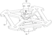
fig. 5 is a schematic view of the entire structure of the rotating mechanism of the present invention.
In the figure: 1. a frame; 2. a first clamping mechanism; 21. a supporting seat; 22. fixing a die holder; 221. a first groove; 23. a movable die holder; 231. a second groove; 24. a first drive assembly; 3. a second clamping mechanism; 31. a connecting member; 32. a fixing plate; 321. a first splint; 33. a movable plate; 331. a second splint; 34. a second drive assembly; 4. a rotation mechanism; 41. a divider; 42. a slip ring; 43. a turntable; 5. a glue dispensing mechanism; 51. dispensing the bottom plate; 52. pushing the plate; 53. dispensing a glue needle; 54. a glue box; 55. a lifting assembly; 551. a first connecting plate; 552. a second connecting plate; 553. a first cylinder; 554. a second cylinder; 56. dispensing driving components; 6. a positioning member; 61. a plate body; 62. positioning a groove; 7. a sensor; 8. a plastic product.
Detailed Description
In order to make the objects, features and advantages of the present invention comprehensible, embodiments accompanied with figures are described in detail below. Several embodiments of the invention are presented in the drawings. This invention may, however, be embodied in many different forms and should not be construed as limited to the embodiments set forth herein.
In the present invention, unless otherwise expressly specified or limited, the terms "mounted," "connected," "secured," and the like are to be construed broadly and can, for example, be fixedly connected, detachably connected, or integrally connected; can be mechanically or electrically connected; they may be connected directly or indirectly through intervening media, or they may be interconnected between two elements. The specific meanings of the above terms in the present invention can be understood by those skilled in the art according to specific situations. The terms "first", "second" and "first" are used for descriptive purposes only and are not to be construed as indicating or implying relative importance or implicitly indicating the number of technical features indicated. Thus, a feature defined as "first" or "second" may explicitly or implicitly include one or more of that feature.
The invention is described in detail below with reference to the figures and examples.
The invention provides a novel glue dispensing device, as shown in fig. 1-5, comprising: the plastic product dispensing machine comprises a rack 1, a first clamping mechanism 2 for clamping a plurality of plastic products 8, a second clamping mechanism 3 for clamping a plurality of connecting wires which are correspondingly spliced with the plastic products 8 one by one, a rotating mechanism 4 for driving the first clamping mechanism 2 and the second clamping mechanism 3 to rotate, a dispensing mechanism 5 for dispensing glue at the splicing positions of the plastic products 8 and the connecting wires, and a positioning piece 6 for positioning the plastic products 8; the rotating mechanism 4 and the adhesive dispensing mechanism 5 are both arranged on the rack 1; the first clamping mechanism 2 is arranged on the rotating mechanism 4; the second clamping mechanism 3 is rotatably arranged on the first clamping mechanism 2; the positioning piece 6 is arranged on the dispensing mechanism 5; under the condition that the glue dispensing mechanism 5 performs glue dispensing on the insertion joint of the plastic product 8 and the connecting line, the positioning piece 6 is abutted against the plastic product 8; the connecting lines are not shown in the figure.
Specifically, the plastic product 8 is provided with an insertion hole, the connecting line is inserted in the insertion hole, and is rotatably arranged on the first clamping mechanism 2 through the second clamping mechanism 3, and under the condition that the plastic product 8 is clamped on the first clamping mechanism 2, the second clamping mechanism 3 rotates to drive the connecting line to rotate so as to enable the connecting line to be inserted in the insertion hole of the corresponding plastic product 8, so that the adhesive dispensing mechanism 5 can dispense adhesive at the insertion position of the connecting line and the plastic product 8, and in addition, the second clamping mechanism 3 can be driven to rotate through a driving motor in the prior art; through the arrangement of the positioning piece 6, the plastic product 8 on the first clamping mechanism 2 can be positioned, so that the glue dispensing mechanism 5 can be aligned with the splicing position of the plastic product 8 and the connecting line for dispensing; the number of the first clamping mechanisms 2 is four, the four first clamping mechanisms 2 are respectively arranged on four different directions of the rotating mechanism 4, and the number of the second clamping mechanisms 3 is the same as that of the first clamping mechanisms 2; the first clamping mechanism 2 and the second clamping mechanism 3 are driven to rotate through the rotating mechanism 4, so that the first clamping mechanism 2 and the second clamping mechanism 3 can rotate to the next station after the dispensing is finished, such as a gluing station, the conveying is convenient, and the space is saved.
Further, as shown in fig. 1 and 2, the glue dispensing mechanism 5 includes: the glue dispensing device comprises a glue dispensing bottom plate 51, a push plate 52, a plurality of glue dispensing needles 53 for dispensing glue at the splicing positions of the plastic products 8 and the connecting lines in a one-to-one correspondence manner, a glue box 54 for storing glue, a lifting assembly 55 for driving the glue dispensing needles 53 to lift so as to dip the glue in the glue box 54, and a glue dispensing driving assembly 56 for driving the push plate 52 to reciprocate; the dispensing bottom plate 51 is arranged on the rack 1; the glue box 54 and the glue dispensing driving assembly 56 are both arranged on the glue dispensing bottom plate 51; the output end of the dispensing driving assembly 56 is fixedly connected with the push plate 52; the lifting assembly 55 and the positioning piece 6 are arranged on the push plate 52; the dispensing needle 53 is fixedly connected with the output end of the lifting component 55.
In practical applications, the lifting assembly 55 drives the dispensing needle 53 to descend, so that the dispensing needle 53 extends into the glue box 54 to dip the glue in the glue box 54, the lifting assembly 55 then drives the dispensing needle 53 to lift so that the dispensing needle 53 extends completely out of the glue cartridge 54, then the dispensing driving assembly 56 drives the pushing plate 52 to extend out, so that the pushing plate 52 drives the dispensing needle 53 and the lifting assembly 55 to approach the first clamping mechanism 2 until the positioning member 6 abuts against the plastic product 8, then the lifting assembly 55 drives the dispensing needle 53 to descend, dispensing the joint between the plastic product 8 and the connecting line, after dispensing, the lifting assembly 55 drives the dispensing needle 53 to ascend, the dispensing driving assembly 56 drives the push plate 52 to retract, the dispensing needle 53 and the lifting assembly 55 are far away from the first clamping mechanism 2 until the dispensing needle 53 is above the glue box 54, then the lifting component 55 drives the dispensing needle 53 to descend, so that the dispensing needle 53 extends into the glue box 54 for next dispensing; the dispensing driving assembly 56 is an air cylinder in the prior art.
Further, as shown in fig. 2, the positioning member 6 includes: a plate body 61; the plate body 61 is arranged on the push plate 52; the plate body 61 is provided with positioning grooves 62 which are correspondingly abutted with the plastic products 8 one by one; the glue dispensing needles 53 are correspondingly positioned in the positioning grooves 62.
Specifically, in the in-process of gluing, a plurality of plastic products 8 are located a plurality of constant head tanks 62 one-to-one, this moment the grafting department of a plurality of plastic products 8 and a plurality of connecting wire also is located a plurality of constant head tanks 62 one-to-one, a plurality of glue needle 53 also is located a plurality of constant head tanks 62 one-to-one, then lift module 55 drives glue needle 53 and descends, make glue needle 53 glue the point to the grafting department of plastic products 8 and connecting wire, compare in manual glue, the accuracy of gluing to the grafting department of plastic products 8 and connecting wire has also been guaranteed to point had both improved the speed of gluing, the error rate is reduced, production quality and production efficiency are improved, in order to satisfy the high efficiency demand of production line.
Further, as shown in fig. 2, the lifting assembly 55 includes: a first connecting plate 551, a second connecting plate 552, a first cylinder 553, and a second cylinder 554; the first air cylinder 553 is disposed on the push plate 52; the output end of the first cylinder 553 is fixedly connected with the second connecting plate 552; the second cylinder 554 is disposed on the second connection plate 552; the output end of the second air cylinder 554 is fixedly connected with a first connecting plate 551; the dispensing needle 53 is disposed on the first connection plate 551.
Specifically, the number of the first cylinders 553 is two and the number of the second cylinders 554 is one in the present application, and the number of the first cylinders 553 and the second cylinders 554 may be increased or decreased according to actual situations in other embodiments; under the condition that the glue in the box 54 is got to the drive point plastic pin 53 dip in, the output of second cylinder 554 withdraws or stretches out to drive first connecting plate 551 and point plastic pin 53 and rise or descend and get in order to realize the dipping of point plastic pin 53 to gluing glue in the box 54, withdraw or stretch out through the output of first cylinder 553, drive second cylinder 554 and descend or rise, can realize adjusting the height of second cylinder 554, adjust with the highest rising height and the minimum descending height to first connecting plate 551 and point plastic pin 53.
Further, as shown in fig. 1 and 2, the glue box 54 is provided with a plurality of glue taking holes corresponding to the glue dispensing needles 53 one to one. Through getting the setting of gluing the hole, can guarantee to glue dipping of needle 53 to gluing in the box 54 and get.
Further, as shown in fig. 3 and 4, the first clamping mechanism 2 includes: the device comprises a supporting seat 21, a fixed die holder 22, a movable die holder 23 and a first driving assembly 24 for driving the movable die holder 23 to reciprocate; the supporting seat 21 is arranged on the rotating mechanism 4; the fixed die holder 22 and the first driving assembly 24 are both arranged on the supporting seat 21; the output end of the first driving component 24 is fixedly connected with the movable die holder 23; a plurality of first grooves 221 for correspondingly abutting against one side of the plastic products 8 one by one are formed in the fixed die holder 22; the movable mold base 23 is provided with a plurality of second grooves 231 for correspondingly abutting against the other sides of the plurality of plastic products 8 one by one.
Specifically, the first driving component 24 drives the movable mold seat 23 to reciprocate to move closer to or away from the fixed mold seat 22, so that the movable mold seat 23 and the fixed mold seat 22 clamp or release the plastic product 8, and when the movable mold seat 23 and the fixed mold seat 22 clamp the plastic product 8, the first groove 221 abuts against one side of the plastic product 8, and the second groove 231 abuts against the other side of the plastic product 8.
Further, as shown in fig. 3 and 4, the second clamping mechanism 3 includes: the connecting member 31, the fixed plate 32, the movable plate 33 and the second driving assembly 34 for driving the movable plate 33 to reciprocate; the connecting piece 31 is rotatably arranged on the supporting seat 21; the fixing plate 32 and the second driving assembly 34 are both arranged on the connecting piece 31; the output end of the second driving assembly 34 is fixedly connected with the movable plate 33; the fixing plate 32 is provided with a plurality of first clamping plates 321 which are correspondingly abutted with one sides of the connecting wires one by one; the movable plate 33 is provided with a plurality of second clamping plates 331 which are correspondingly abutted against the other sides of the plurality of materials one by one.
Specifically, the first driving assembly 24 and the second driving assembly 34 both adopt cylinders, and the second driving assembly 34 drives the movable plate 33 to reciprocate, so that the second clamping plate 331 on the movable plate 33 is close to or away from the first clamping plate 321, so that the first clamping plate 321 and the second clamping plate 331 clamp or loosen the connecting line, and the connecting line and the plastic product 8 can be prevented from shaking or deviating in the process of dispensing under the condition that the first clamping mechanism 2 clamps the plastic product 8 and the second clamping mechanism 3 clamps the connecting line, thereby improving the dispensing quality; through connecting piece 31 rotationally sets up on supporting seat 21, can adjust the angle between connecting piece 31 and the supporting seat 21 in order to adapt to the length of connecting wire, the practicality is stronger.
Further, as shown in fig. 4, the movable plate 33 is slidably disposed on the connecting member 31; the fixing plate 32 is provided with a through hole; the first clamping plate 321 is arranged in the through hole; the second clamping plate 331 slides in the through hole, so that the stability of the second driving assembly 34 driving the movable plate 33 to reciprocate is improved.
Further, as shown in fig. 5, the rotation mechanism 4 includes: a divider 41, a slip ring 42, and a turntable 43; the divider 41 is arranged on the frame 1; the stator 421 of the slip ring 42 is arranged on the divider 41; the rotor 422 of the slip ring 42 is fixedly connected with the output end of the divider 41; the turntable 43 is fixedly connected with the rotor of the slip ring 42; the first clamping mechanism 2 is fixedly connected with the rotating disc 43. Specifically, the divider 41 in the present application is a cam divider 41, which can realize that the turntable 43 drives the first clamping mechanism 2 and the second clamping mechanism 3 to precisely rotate to other stations such as a dispensing station or a glue station.
Further, still include: the controller and the sensor 7 are used for detecting whether the first clamping mechanism 2 clamps the plastic product 8; the sensor 7 is arranged on the dispensing mechanism 5; the sensor 7, the dispensing driving assembly 56, the lifting assembly 55, the first driving assembly 24, the second driving assembly 34 and the divider 41 are all electrically connected with the controller.
The sensor 7 in the application adopts a laser sensor 7, and the controller adopts a singlechip and other controllers in the prior art; in practical application, after the plastic product 8 is conveyed to the first clamping mechanism 2, the controller controls the first driving component 24 to move so that the fixed die holder 22 and the movable die holder 23 clamp the plastic product 8 tightly, after the connecting line is conveyed to the second clamping mechanism 3, the controller controls the second driving component 34 to move so that the first clamping plate 321 and the second clamping plate 331 clamp the connecting line, under the condition that the laser sensor 7 detects that the plastic product 8 is clamped on the first clamping mechanism 2, the controller controls the glue dispensing driving component 56 and the lifting component 55 of the glue dispensing mechanism 5 to dispense glue on the splicing part of the plastic product 8 and the connecting line, and after the glue dispensing is completed, the rotating mechanism 4 is controlled to rotate to convey the plastic product 8 and the connecting line after the glue dispensing to the next station, so that the automatic glue dispensing of the plastic product 8 and the connecting line is completed.
According to the novel glue dispensing device, the second clamping mechanism 3 is rotatably arranged on the first clamping mechanism 2, the second clamping mechanism 3 rotates to drive the connecting wire to rotate so as to be inserted into the corresponding inserting hole of the plastic product 8, and the glue dispensing mechanism 5 is convenient to dispense glue at the inserting position of the connecting wire and the plastic product 8; through the arrangement of the positioning piece 6, the plastic product 8 on the first clamping mechanism 2 can be positioned, so that the glue dispensing mechanism 5 can be aligned with the splicing position of the plastic product 8 and the connecting line for dispensing; the first clamping mechanism 2 and the second clamping mechanism 3 are driven to rotate through the rotating mechanism 4, so that the first clamping mechanism 2 and the second clamping mechanism 3 can rotate to the next station after the dispensing is finished, such as a gluing station, the conveying is convenient, and the space is saved.
The above description is only a preferred embodiment of the present invention, and the protection scope of the present invention is not limited to the above embodiments, and all technical solutions belonging to the idea of the present invention belong to the protection scope of the present invention. It should be noted that modifications and embellishments within the scope of the invention may occur to those skilled in the art without departing from the principle of the invention, and are considered to be within the scope of the invention.
Claims (10)
1. The utility model provides a novel adhesive deposite device which characterized in that includes: the plastic product positioning device comprises a rack, a first clamping mechanism for clamping a plurality of plastic products, a second clamping mechanism for clamping a plurality of connecting wires which are in one-to-one corresponding insertion connection with the plurality of plastic products, a rotating mechanism for driving the first clamping mechanism and the second clamping mechanism to rotate, a glue dispensing mechanism for dispensing glue at the insertion connection positions of the plurality of plastic products and the plurality of connecting wires, and a positioning piece for positioning the plastic products; the rotating mechanism and the adhesive dispensing mechanism are both arranged on the rack; the first clamping mechanism is arranged on the rotating mechanism; the second clamping mechanism is rotatably arranged on the first clamping mechanism; the positioning piece is arranged on the dispensing mechanism; the glue dispensing mechanism is used for dispensing glue at the splicing position of the plastic product and the connecting line, and the positioning piece is abutted to the plastic product.
2. The novel dispensing device of claim 1, wherein the dispensing mechanism comprises: the glue dispensing device comprises a glue dispensing bottom plate, a push plate, a plurality of glue dispensing needles, a glue box, a lifting assembly and a glue dispensing driving assembly, wherein the glue dispensing needles are used for dispensing glue on the splicing positions of a plurality of plastic products and a plurality of connecting wires in a one-to-one correspondence mode; the dispensing bottom plate is arranged on the rack; the glue box and the glue dispensing driving assembly are arranged on the glue dispensing bottom plate; the output end of the dispensing driving assembly is fixedly connected with the push plate; the lifting assembly and the positioning piece are arranged on the push plate; the glue dispensing needle is fixedly connected with the output end of the lifting assembly.
3. A novel dispensing device as claimed in claim 2, characterized in that said positioning member comprises: a plate body; the plate body is arranged on the push plate; the plate body is provided with positioning grooves which are used for correspondingly abutting against a plurality of plastic products one by one; the glue dispensing needles are correspondingly positioned in the positioning grooves one by one.
4. The novel dispensing device of claim 2, wherein the lifting assembly comprises: the device comprises a first connecting plate, a second connecting plate, a first air cylinder and a second air cylinder; the first air cylinder is arranged on the push plate; the output end of the first cylinder is fixedly connected with the second connecting plate; the second cylinder is arranged on the second connecting plate; the output end of the second cylinder is fixedly connected with the first connecting plate; the glue dispensing needle is arranged on the first connecting plate.
5. A novel dispensing device according to claim 2, wherein the glue box is provided with a plurality of glue taking holes corresponding to the plurality of dispensing needles one to one.
6. The novel dispensing apparatus of claim 1, wherein the first clamping mechanism comprises: the device comprises a supporting seat, a fixed die holder, a movable die holder and a first driving assembly for driving the movable die holder to reciprocate; the supporting seat is arranged on the rotating mechanism; the fixed die holder and the first driving assembly are arranged on the supporting seat; the output end of the first driving assembly is fixedly connected with the movable die holder; a plurality of first grooves which are used for correspondingly abutting against one side of the plastic products one by one are formed in the fixed die holder; and the movable die holder is provided with a plurality of second grooves which are correspondingly abutted with the other sides of the plastic products one by one.
7. The novel dispensing apparatus of claim 6, wherein the second clamping mechanism comprises: the second driving assembly is used for driving the movable plate to do reciprocating motion; the connecting piece is rotatably arranged on the supporting seat; the fixed plate and the second driving assembly are arranged on the connecting piece; the output end of the second driving assembly is fixedly connected with the movable plate; the fixing plate is provided with a plurality of first clamping plates which are correspondingly abutted with one sides of the connecting wires one by one; the movable plate is provided with a plurality of second clamping plates which are correspondingly abutted against the other sides of the materials one by one.
8. The novel dispensing device as claimed in claim 7, wherein the movable plate is slidably disposed on the connecting member; the fixing plate is provided with a through hole; the first clamping plate is arranged in the through hole; the second clamping plate slides in the through hole.
9. The novel dispensing device of claim 1, wherein the rotating mechanism comprises: a divider, a slip ring and a turntable; the divider is arranged on the frame; the stator of the slip ring is arranged on the divider; the rotor of the slip ring is fixedly connected with the output end of the divider; the turntable is fixedly connected with a rotor of the slip ring; the first clamping mechanism is fixedly connected with the rotary table.
10. A novel dispensing device as claimed in any one of claims 1-9, further comprising: the controller and the sensor are used for detecting whether the first clamping mechanism clamps the plastic product or not; the sensor is arranged on the dispensing mechanism; the sensor, the glue dispensing mechanism, the first clamping mechanism, the second clamping mechanism and the rotating mechanism are all electrically connected with the controller.
Priority Applications (1)
| Application Number | Priority Date | Filing Date | Title |
|---|---|---|---|
| CN202210159917.0A CN114505203B (en) | 2022-02-22 | 2022-02-22 | Adhesive dispensing device |
Applications Claiming Priority (1)
| Application Number | Priority Date | Filing Date | Title |
|---|---|---|---|
| CN202210159917.0A CN114505203B (en) | 2022-02-22 | 2022-02-22 | Adhesive dispensing device |
Publications (2)
| Publication Number | Publication Date |
|---|---|
| CN114505203A true CN114505203A (en) | 2022-05-17 |
| CN114505203B CN114505203B (en) | 2023-07-25 |
Family
ID=81552975
Family Applications (1)
| Application Number | Title | Priority Date | Filing Date |
|---|---|---|---|
| CN202210159917.0A Active CN114505203B (en) | 2022-02-22 | 2022-02-22 | Adhesive dispensing device |
Country Status (1)
| Country | Link |
|---|---|
| CN (1) | CN114505203B (en) |
Citations (14)
| Publication number | Priority date | Publication date | Assignee | Title |
|---|---|---|---|---|
| US20060207717A1 (en) * | 2005-03-18 | 2006-09-21 | Bruce Campbell | Magnetic wick-clip holder and wick-clip inserter and method employing same |
| WO2018090391A1 (en) * | 2016-11-17 | 2018-05-24 | 刘子琪 | Device for producing writing brush |
| WO2018107817A1 (en) * | 2016-12-14 | 2018-06-21 | 广州市永合祥自动化设备科技有限公司 | Terminal automatic glue dispensing machine |
| CN108405267A (en) * | 2018-05-25 | 2018-08-17 | 东莞理工学院 | A kind of loudspeaker combination dispenser facilitating blanking |
| CN109158263A (en) * | 2018-10-15 | 2019-01-08 | 中南大学 | A kind of photodetector automatic coupling dispensing solidification equipment |
| US20190015864A1 (en) * | 2017-07-11 | 2019-01-17 | Boe Technology Group Co., Ltd. | Adhesive dispenser |
| CN208727877U (en) * | 2018-07-18 | 2019-04-12 | 广东若铂智能机器人有限公司 | A kind of novel silicon wafer automatic dropping glue equipment |
| CN209362858U (en) * | 2018-10-31 | 2019-09-10 | 广东若铂智能机器人有限公司 | A kind of three axis automatic glue dispensing mechanisms |
| CN209646885U (en) * | 2019-01-31 | 2019-11-19 | 宁波市鄞州顺和自动化设备有限公司 | A kind of adhesive dispensing robot |
| CN210230495U (en) * | 2019-06-12 | 2020-04-03 | 东莞市合鼎盛自动化设备有限公司 | Relay point gum machine |
| CN211804286U (en) * | 2019-11-21 | 2020-10-30 | 苏州市毅田自动化科技有限公司 | Three-part junction box line body assembling device |
| CN213194338U (en) * | 2020-07-08 | 2021-05-14 | 惠州金源精密自动化设备有限公司 | Dispensing mechanism and battery |
| CN215478264U (en) * | 2021-05-08 | 2022-01-11 | 广东若铂智能机器人有限公司 | Novel plastic bubble intelligence is got material device |
| CN215478184U (en) * | 2021-05-06 | 2022-01-11 | 广东若铂智能机器人有限公司 | Novel single-shaft robot feeding and positioning device |
-
2022
- 2022-02-22 CN CN202210159917.0A patent/CN114505203B/en active Active
Patent Citations (14)
| Publication number | Priority date | Publication date | Assignee | Title |
|---|---|---|---|---|
| US20060207717A1 (en) * | 2005-03-18 | 2006-09-21 | Bruce Campbell | Magnetic wick-clip holder and wick-clip inserter and method employing same |
| WO2018090391A1 (en) * | 2016-11-17 | 2018-05-24 | 刘子琪 | Device for producing writing brush |
| WO2018107817A1 (en) * | 2016-12-14 | 2018-06-21 | 广州市永合祥自动化设备科技有限公司 | Terminal automatic glue dispensing machine |
| US20190015864A1 (en) * | 2017-07-11 | 2019-01-17 | Boe Technology Group Co., Ltd. | Adhesive dispenser |
| CN108405267A (en) * | 2018-05-25 | 2018-08-17 | 东莞理工学院 | A kind of loudspeaker combination dispenser facilitating blanking |
| CN208727877U (en) * | 2018-07-18 | 2019-04-12 | 广东若铂智能机器人有限公司 | A kind of novel silicon wafer automatic dropping glue equipment |
| CN109158263A (en) * | 2018-10-15 | 2019-01-08 | 中南大学 | A kind of photodetector automatic coupling dispensing solidification equipment |
| CN209362858U (en) * | 2018-10-31 | 2019-09-10 | 广东若铂智能机器人有限公司 | A kind of three axis automatic glue dispensing mechanisms |
| CN209646885U (en) * | 2019-01-31 | 2019-11-19 | 宁波市鄞州顺和自动化设备有限公司 | A kind of adhesive dispensing robot |
| CN210230495U (en) * | 2019-06-12 | 2020-04-03 | 东莞市合鼎盛自动化设备有限公司 | Relay point gum machine |
| CN211804286U (en) * | 2019-11-21 | 2020-10-30 | 苏州市毅田自动化科技有限公司 | Three-part junction box line body assembling device |
| CN213194338U (en) * | 2020-07-08 | 2021-05-14 | 惠州金源精密自动化设备有限公司 | Dispensing mechanism and battery |
| CN215478184U (en) * | 2021-05-06 | 2022-01-11 | 广东若铂智能机器人有限公司 | Novel single-shaft robot feeding and positioning device |
| CN215478264U (en) * | 2021-05-08 | 2022-01-11 | 广东若铂智能机器人有限公司 | Novel plastic bubble intelligence is got material device |
Also Published As
| Publication number | Publication date |
|---|---|
| CN114505203B (en) | 2023-07-25 |
Similar Documents
| Publication | Publication Date | Title |
|---|---|---|
| CN108526886B (en) | Camera automatic assembly machine | |
| CN106826160B (en) | Dispensing pressure maintaining device and method | |
| CN109968023A (en) | A kind of laser diode automatic assembly equipment | |
| CN114505203A (en) | Novel glue dispensing device | |
| CN112357162B (en) | Automatic winding and packaging equipment | |
| CN210614204U (en) | Gluing mechanism for rotor shaft of automobile lifting motor | |
| CN209829442U (en) | Dispensing system | |
| CN116487720A (en) | Self-adaptive clamping device for flexible production line of electric automobile power battery | |
| CN215141575U (en) | Combustible cartridge case rubber coating sealing device | |
| CN116160137A (en) | Multi-station turntable type laser engraving device | |
| CN214558813U (en) | Automatic assembling device for optical fiber metal connecting piece | |
| CN209993567U (en) | Automatic semiconductor packaging device | |
| CN209240473U (en) | A kind of rotating disc type high-pressure forming machine | |
| CN217911282U (en) | Promote hot melt adhesive point gum machine of efficiency of gluing | |
| CN214554903U (en) | Sound membrane radian automatic molding point gum machine | |
| CN214487608U (en) | Lens assembling equipment | |
| CN115394687B (en) | Chip mounter | |
| CN220509981U (en) | Mould strip carrier and paster equipment | |
| CN220941523U (en) | Dispensing mechanism | |
| CN111628387B (en) | Card holds in palm bullet spare assembly system | |
| CN220822865U (en) | Accurate alignment assembling machine for stator and rotor of motor | |
| CN212638972U (en) | Material tray conveying device for high-frequency gumming machine | |
| CN217222178U (en) | Automatic dispensing installation mechanism | |
| CN214012910U (en) | Linear die bonder | |
| CN220091922U (en) | Rotor rubberizing device of brushless motor |
Legal Events
| Date | Code | Title | Description |
|---|---|---|---|
| PB01 | Publication | ||
| PB01 | Publication | ||
| SE01 | Entry into force of request for substantive examination | ||
| SE01 | Entry into force of request for substantive examination | ||
| GR01 | Patent grant | ||
| GR01 | Patent grant |