CN114383109A - Multifunctional multiplexing slender through lamp and mounting structure thereof - Google Patents
Multifunctional multiplexing slender through lamp and mounting structure thereof Download PDFInfo
- Publication number
- CN114383109A CN114383109A CN202111651131.2A CN202111651131A CN114383109A CN 114383109 A CN114383109 A CN 114383109A CN 202111651131 A CN202111651131 A CN 202111651131A CN 114383109 A CN114383109 A CN 114383109A
- Authority
- CN
- China
- Prior art keywords
- light
- lamp
- emitting module
- light source
- fixed
- Prior art date
- Legal status (The legal status is an assumption and is not a legal conclusion. Google has not performed a legal analysis and makes no representation as to the accuracy of the status listed.)
- Granted
Links
Images


Classifications
-
- F—MECHANICAL ENGINEERING; LIGHTING; HEATING; WEAPONS; BLASTING
- F21—LIGHTING
- F21S—NON-PORTABLE LIGHTING DEVICES; SYSTEMS THEREOF; VEHICLE LIGHTING DEVICES SPECIALLY ADAPTED FOR VEHICLE EXTERIORS
- F21S43/00—Signalling devices specially adapted for vehicle exteriors, e.g. brake lamps, direction indicator lights or reversing lights
- F21S43/10—Signalling devices specially adapted for vehicle exteriors, e.g. brake lamps, direction indicator lights or reversing lights characterised by the light source
-
- F—MECHANICAL ENGINEERING; LIGHTING; HEATING; WEAPONS; BLASTING
- F21—LIGHTING
- F21S—NON-PORTABLE LIGHTING DEVICES; SYSTEMS THEREOF; VEHICLE LIGHTING DEVICES SPECIALLY ADAPTED FOR VEHICLE EXTERIORS
- F21S43/00—Signalling devices specially adapted for vehicle exteriors, e.g. brake lamps, direction indicator lights or reversing lights
- F21S43/40—Signalling devices specially adapted for vehicle exteriors, e.g. brake lamps, direction indicator lights or reversing lights characterised by the combination of reflectors and refractors
-
- B—PERFORMING OPERATIONS; TRANSPORTING
- B60—VEHICLES IN GENERAL
- B60Q—ARRANGEMENT OF SIGNALLING OR LIGHTING DEVICES, THE MOUNTING OR SUPPORTING THEREOF OR CIRCUITS THEREFOR, FOR VEHICLES IN GENERAL
- B60Q1/00—Arrangement of optical signalling or lighting devices, the mounting or supporting thereof or circuits therefor
- B60Q1/02—Arrangement of optical signalling or lighting devices, the mounting or supporting thereof or circuits therefor the devices being primarily intended to illuminate the way ahead or to illuminate other areas of way or environments
- B60Q1/04—Arrangement of optical signalling or lighting devices, the mounting or supporting thereof or circuits therefor the devices being primarily intended to illuminate the way ahead or to illuminate other areas of way or environments the devices being headlights
- B60Q1/18—Arrangement of optical signalling or lighting devices, the mounting or supporting thereof or circuits therefor the devices being primarily intended to illuminate the way ahead or to illuminate other areas of way or environments the devices being headlights being additional front lights
- B60Q1/20—Fog lights
-
- B—PERFORMING OPERATIONS; TRANSPORTING
- B60—VEHICLES IN GENERAL
- B60Q—ARRANGEMENT OF SIGNALLING OR LIGHTING DEVICES, THE MOUNTING OR SUPPORTING THEREOF OR CIRCUITS THEREFOR, FOR VEHICLES IN GENERAL
- B60Q1/00—Arrangement of optical signalling or lighting devices, the mounting or supporting thereof or circuits therefor
- B60Q1/02—Arrangement of optical signalling or lighting devices, the mounting or supporting thereof or circuits therefor the devices being primarily intended to illuminate the way ahead or to illuminate other areas of way or environments
- B60Q1/22—Arrangement of optical signalling or lighting devices, the mounting or supporting thereof or circuits therefor the devices being primarily intended to illuminate the way ahead or to illuminate other areas of way or environments for reverse drive
-
- B—PERFORMING OPERATIONS; TRANSPORTING
- B60—VEHICLES IN GENERAL
- B60Q—ARRANGEMENT OF SIGNALLING OR LIGHTING DEVICES, THE MOUNTING OR SUPPORTING THEREOF OR CIRCUITS THEREFOR, FOR VEHICLES IN GENERAL
- B60Q1/00—Arrangement of optical signalling or lighting devices, the mounting or supporting thereof or circuits therefor
- B60Q1/26—Arrangement of optical signalling or lighting devices, the mounting or supporting thereof or circuits therefor the devices being primarily intended to indicate the vehicle, or parts thereof, or to give signals, to other traffic
- B60Q1/34—Arrangement of optical signalling or lighting devices, the mounting or supporting thereof or circuits therefor the devices being primarily intended to indicate the vehicle, or parts thereof, or to give signals, to other traffic for indicating change of drive direction
-
- B—PERFORMING OPERATIONS; TRANSPORTING
- B60—VEHICLES IN GENERAL
- B60Q—ARRANGEMENT OF SIGNALLING OR LIGHTING DEVICES, THE MOUNTING OR SUPPORTING THEREOF OR CIRCUITS THEREFOR, FOR VEHICLES IN GENERAL
- B60Q1/00—Arrangement of optical signalling or lighting devices, the mounting or supporting thereof or circuits therefor
- B60Q1/26—Arrangement of optical signalling or lighting devices, the mounting or supporting thereof or circuits therefor the devices being primarily intended to indicate the vehicle, or parts thereof, or to give signals, to other traffic
- B60Q1/44—Arrangement of optical signalling or lighting devices, the mounting or supporting thereof or circuits therefor the devices being primarily intended to indicate the vehicle, or parts thereof, or to give signals, to other traffic for indicating braking action or preparation for braking, e.g. by detection of the foot approaching the brake pedal
-
- F—MECHANICAL ENGINEERING; LIGHTING; HEATING; WEAPONS; BLASTING
- F21—LIGHTING
- F21S—NON-PORTABLE LIGHTING DEVICES; SYSTEMS THEREOF; VEHICLE LIGHTING DEVICES SPECIALLY ADAPTED FOR VEHICLE EXTERIORS
- F21S43/00—Signalling devices specially adapted for vehicle exteriors, e.g. brake lamps, direction indicator lights or reversing lights
- F21S43/30—Signalling devices specially adapted for vehicle exteriors, e.g. brake lamps, direction indicator lights or reversing lights characterised by reflectors
- F21S43/31—Optical layout thereof
- F21S43/315—Optical layout thereof using total internal reflection
-
- F—MECHANICAL ENGINEERING; LIGHTING; HEATING; WEAPONS; BLASTING
- F21—LIGHTING
- F21S—NON-PORTABLE LIGHTING DEVICES; SYSTEMS THEREOF; VEHICLE LIGHTING DEVICES SPECIALLY ADAPTED FOR VEHICLE EXTERIORS
- F21S43/00—Signalling devices specially adapted for vehicle exteriors, e.g. brake lamps, direction indicator lights or reversing lights
- F21S43/50—Signalling devices specially adapted for vehicle exteriors, e.g. brake lamps, direction indicator lights or reversing lights characterised by aesthetic components not otherwise provided for, e.g. decorative trim, partition walls or covers
-
- F—MECHANICAL ENGINEERING; LIGHTING; HEATING; WEAPONS; BLASTING
- F21—LIGHTING
- F21V—FUNCTIONAL FEATURES OR DETAILS OF LIGHTING DEVICES OR SYSTEMS THEREOF; STRUCTURAL COMBINATIONS OF LIGHTING DEVICES WITH OTHER ARTICLES, NOT OTHERWISE PROVIDED FOR
- F21V19/00—Fastening of light sources or lamp holders
-
- F—MECHANICAL ENGINEERING; LIGHTING; HEATING; WEAPONS; BLASTING
- F21—LIGHTING
- F21V—FUNCTIONAL FEATURES OR DETAILS OF LIGHTING DEVICES OR SYSTEMS THEREOF; STRUCTURAL COMBINATIONS OF LIGHTING DEVICES WITH OTHER ARTICLES, NOT OTHERWISE PROVIDED FOR
- F21V21/00—Supporting, suspending, or attaching arrangements for lighting devices; Hand grips
-
- B—PERFORMING OPERATIONS; TRANSPORTING
- B60—VEHICLES IN GENERAL
- B60Q—ARRANGEMENT OF SIGNALLING OR LIGHTING DEVICES, THE MOUNTING OR SUPPORTING THEREOF OR CIRCUITS THEREFOR, FOR VEHICLES IN GENERAL
- B60Q2400/00—Special features or arrangements of exterior signal lamps for vehicles
- B60Q2400/20—Multi-color single source or LED matrix, e.g. yellow blinker and red brake lamp generated by single lamp
-
- F—MECHANICAL ENGINEERING; LIGHTING; HEATING; WEAPONS; BLASTING
- F21—LIGHTING
- F21W—INDEXING SCHEME ASSOCIATED WITH SUBCLASSES F21K, F21L, F21S and F21V, RELATING TO USES OR APPLICATIONS OF LIGHTING DEVICES OR SYSTEMS
- F21W2103/00—Exterior vehicle lighting devices for signalling purposes
- F21W2103/10—Position lights
-
- F—MECHANICAL ENGINEERING; LIGHTING; HEATING; WEAPONS; BLASTING
- F21—LIGHTING
- F21W—INDEXING SCHEME ASSOCIATED WITH SUBCLASSES F21K, F21L, F21S and F21V, RELATING TO USES OR APPLICATIONS OF LIGHTING DEVICES OR SYSTEMS
- F21W2103/00—Exterior vehicle lighting devices for signalling purposes
- F21W2103/20—Direction indicator lights
-
- F—MECHANICAL ENGINEERING; LIGHTING; HEATING; WEAPONS; BLASTING
- F21—LIGHTING
- F21W—INDEXING SCHEME ASSOCIATED WITH SUBCLASSES F21K, F21L, F21S and F21V, RELATING TO USES OR APPLICATIONS OF LIGHTING DEVICES OR SYSTEMS
- F21W2103/00—Exterior vehicle lighting devices for signalling purposes
- F21W2103/35—Brake lights
-
- F—MECHANICAL ENGINEERING; LIGHTING; HEATING; WEAPONS; BLASTING
- F21—LIGHTING
- F21W—INDEXING SCHEME ASSOCIATED WITH SUBCLASSES F21K, F21L, F21S and F21V, RELATING TO USES OR APPLICATIONS OF LIGHTING DEVICES OR SYSTEMS
- F21W2103/00—Exterior vehicle lighting devices for signalling purposes
- F21W2103/40—Rear fog lights
-
- F—MECHANICAL ENGINEERING; LIGHTING; HEATING; WEAPONS; BLASTING
- F21—LIGHTING
- F21W—INDEXING SCHEME ASSOCIATED WITH SUBCLASSES F21K, F21L, F21S and F21V, RELATING TO USES OR APPLICATIONS OF LIGHTING DEVICES OR SYSTEMS
- F21W2103/00—Exterior vehicle lighting devices for signalling purposes
- F21W2103/45—Reversing lights
-
- F—MECHANICAL ENGINEERING; LIGHTING; HEATING; WEAPONS; BLASTING
- F21—LIGHTING
- F21W—INDEXING SCHEME ASSOCIATED WITH SUBCLASSES F21K, F21L, F21S and F21V, RELATING TO USES OR APPLICATIONS OF LIGHTING DEVICES OR SYSTEMS
- F21W2107/00—Use or application of lighting devices on or in particular types of vehicles
- F21W2107/10—Use or application of lighting devices on or in particular types of vehicles for land vehicles
-
- Y—GENERAL TAGGING OF NEW TECHNOLOGICAL DEVELOPMENTS; GENERAL TAGGING OF CROSS-SECTIONAL TECHNOLOGIES SPANNING OVER SEVERAL SECTIONS OF THE IPC; TECHNICAL SUBJECTS COVERED BY FORMER USPC CROSS-REFERENCE ART COLLECTIONS [XRACs] AND DIGESTS
- Y02—TECHNOLOGIES OR APPLICATIONS FOR MITIGATION OR ADAPTATION AGAINST CLIMATE CHANGE
- Y02B—CLIMATE CHANGE MITIGATION TECHNOLOGIES RELATED TO BUILDINGS, e.g. HOUSING, HOUSE APPLIANCES OR RELATED END-USER APPLICATIONS
- Y02B20/00—Energy efficient lighting technologies, e.g. halogen lamps or gas discharge lamps
- Y02B20/40—Control techniques providing energy savings, e.g. smart controller or presence detection
Abstract
The utility model discloses a multifunctional multiplexing slender through lamp and a mounting structure thereof, wherein the slender through lamp comprises a movable rear lamp and fixed rear lamps symmetrically arranged at the left side and the right side of the movable rear lamp; the light-emitting module for fixing the rear lamp consists of a first light-emitting module and a second light-emitting module, the first light-emitting module consists of a plurality of brake lamp light sources and position lamp light sources, and the second light-emitting module consists of a plurality of steering lamp light sources and position lamp light sources; the movable rear lamp comprises a fourth light-emitting module and a third light-emitting module arranged on two sides of the fourth light-emitting module, the third light-emitting module is composed of a plurality of functional light sources and position light sources, and the fourth light-emitting module is composed of a plurality of position light sources; a first thick-wall condenser is arranged above the first light-emitting module, the second light-emitting module and the third light-emitting module; and a second thick-wall condenser is arranged above the fourth light-emitting module. The elongated through light enables the function of a position light, a turn light and a brake light to be reused, and an elongated feature can be formed at the rear of the automobile.
Description
Technical Field
The utility model belongs to the technical field of automobile electric appliances, and particularly relates to a multifunctional multiplexing slender through lamp and a mounting structure thereof.
Background
The external lamp of the automobile is an important element of appearance aesthetic besides the regulation function, and as the design of the whole automobile facing the future, the lamp is slender and the function is reused. But the difficulty of the lamp self-engineering is high, and the problem of poor matching with the clearance surface of the peripheral parts is caused.
Chinese patent CN207661696U discloses a combined rear lamp assembly, and specifically discloses that the combined rear lamp assembly is composed of a light guide, a decorative frame, an inner lens, a lamp body and two circuit boards with LED light sources; when the LED lamp is large in size and large in span, the requirement of uniform light emission can be met, and the cost is low. But it is only a single function and cannot meet the requirement of multi-function multiplexing.
Chinese patent CN113188099A discloses a through type rear light, which realizes the reduction of the brightness difference caused by the area difference between the movable rear position light and the fixed rear position light by the lens of the fixed side position light distribution lens and the semi-transparent lens of the movable side position light distribution lens. But the function multiplexing situations of position lamps and brake lamps, no turn lamps and the like are only adopted; it has no slender features after the existence of functional partition.
Disclosure of Invention
In view of the above-mentioned shortcomings of the prior art, it is an object of the present invention to provide a multifunctional reusable elongated through light and a mounting structure thereof, which can realize the function reuse of a position light, a turn light and a stop light and can form an elongated feature in the rear of an automobile.
The technical scheme of the utility model is realized as follows:
a multifunctional multiplexing slender through lamp comprises a movable back lamp and fixed back lamps symmetrically arranged on the left side and the right side of the movable back lamp; the fixed rear lamp and the movable rear lamp respectively comprise a lamp shell, a lens and a light-emitting module; the rear lamp fixing device comprises a rear lamp fixing device and a rear lamp fixing device, wherein the rear lamp fixing device is characterized in that a light emitting module of the rear lamp is composed of a first light emitting module and a second light emitting module, the first light emitting module is located on the outer side of the second light emitting module, the first light emitting module is composed of a plurality of brake lamp light sources and position lamp light sources, and the second light emitting module is composed of a plurality of steering lamp light sources and position lamp light sources.
The movable rear lamp comprises a fourth light-emitting module and a third light-emitting module arranged on two sides of the fourth light-emitting module, the third light-emitting module is composed of a plurality of functional light sources and position light sources, and the fourth light-emitting module is composed of a plurality of position light sources.
A first thick-wall condenser is arranged above the first light-emitting module, the second light-emitting module and the third light-emitting module, so that light emitted by the corresponding light-emitting modules can be conveniently reflected for three times and then uniformly penetrates through the corresponding lens to be emitted to the front and back; and a second thick-wall condenser is arranged above the fourth light-emitting module, so that light emitted by the corresponding fourth light-emitting module can be emitted to the right back through the corresponding lens after being totally reflected once.
Furthermore, the first light-emitting module is composed of a plurality of first light-emitting units in parallel, each first light-emitting unit is composed of a stop lamp light source and position lamp light sources arranged on the left side and the right side of the stop lamp light source, and the stop lamp light source and the two position lamp light sources are located on the same straight line.
Furthermore, the second light-emitting module is composed of a plurality of second light-emitting units in parallel, each second light-emitting unit is composed of a turn light source and position light sources arranged on the left side and the right side of the turn light source, and the turn light source and the two position light sources are located on the same straight line.
Further, the functional light source is one of a steering light source, a reversing light source, a rear fog light source or a brake light source.
Furthermore, the third light-emitting module is composed of a plurality of third light-emitting units in parallel, each third light-emitting unit is composed of a functional lamp light source and position lamp light sources arranged on the left side and the right side of the functional lamp light source, and the functional lamp light source and the two position lamp light sources are located on the same straight line.
Furthermore, the light distribution lenses of the fixed rear lamp and the movable rear lamp are respectively composed of a transparent light distribution lens and a black light distribution lens, the black light distribution lens is arranged on the inner side of the transparent light distribution lens, and the middle part of the black light distribution lens is provided with a strip-shaped light hole, so that light emitted by the light emitting module can penetrate through the light hole to be emitted out of the transparent light distribution lens after being reflected by the thick-wall condenser.
Furthermore, the fourth light emitting module is composed of two fifth light emitting modules which are symmetrically arranged.
The utility model provides a multi-functional multiplexing slender mounting structure that runs through lamp, is including running through the lamp, run through the lamp and be preceding multi-functional multiplexing slender lamp that runs through, two fixed back lights that run through the lamp set up respectively and enclose fixed side in the car both sides, and the activity back light that runs through the lamp sets up the activity side at the back of the body door of car.
Further, still include the plastics decoration and locate the automobile body panel beating that runs through the lamp top, the lamp body of the fixed back lamp that runs through the lamp and the activity back lamp is fixed with the automobile body panel beating that corresponds respectively to run through the lamp and fix on the automobile body panel beating, the plastics decoration is located and is run through the lamp outside and be located and run through lamp middle and lower part, and to shield lower part in will running through the lamp, make and run through the lamp and realize long and thin effect.
Furthermore, the upper parts behind the lamp shells of the fixed rear lamp and the movable rear lamp penetrating through the lamps are fixed with corresponding vehicle body metal plates through a plurality of hot-stamping studs and bolts; the lamp body lower part of the fixed rear lamp and the movable rear lamp which run through the lamp is provided with mounting lugs, and the lamp bodies are fixed with the metal plate of the vehicle body through a plurality of hot stamping studs or tightening studs and bolts.
Compared with the prior art, the utility model has the following beneficial effects:
1. the thick-wall condenser is arranged above the light-emitting module, so that light emitted by the through lamp can form a slender shape, and meanwhile, the functions of the position lamp, the steering lamp and the brake lamp can be reused through the design of the light-emitting module, and the functions of the rear fog lamp and the backup lamp can be realized according to requirements.
2. The light emitting area of the through lamp can be divided into a function multiplexing area and a single function area, the light emitting modules corresponding to the function multiplexing area are composed of a plurality of light emitting units, and each light emitting unit is composed of a functional (brake lamp, steering lamp, reversing lamp or rear fog lamp) light source and position lamp light sources arranged on two sides of the functional light source, so that the light emitting uniformity of the position lamps can be effectively ensured.
3. After the elongated through lamp is fixed with the metal plate of the vehicle body, the plastic decorating parts of the rear bumper and the back door are arranged at the middle lower part of the outer side of the elongated through lamp, so that the elongated through lamp can be effectively shielded, and the elongated through lamp can show the elongated effect after being installed on the vehicle body.
Drawings
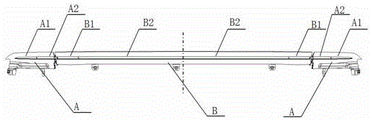
Fig. 1-schematic structural view of the present invention.
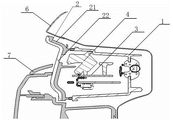
Fig. 2-a schematic cross-sectional view of a functional multiplexing area.
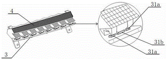
Fig. 3-schematic view of the installation structure of the single function area.
Fig. 4-schematic diagram of total reflection of light within the first thick-walled concentrator.
Fig. 5-schematic diagram of total reflection of light within the second thick-walled concentrator.
Fig. 6-schematic view of the light source and the first thick-walled concentrator of the first, second, and third light emitting modules.
Wherein: a-fixing the rear lamp; a1 — first fixed rear light; a2 — second fixed rear light; b-a movable back light; b1-first active rear light; b2-second active rear light; 1-a lamp housing; 2-a lens; 3-a light emitting module; 31-a light source; 31 a-position light source; 31b a functional light source; 32-light; 4-a first thick-walled concentrator; 5-a second thick-walled concentrator; 6-vehicle body metal plate; 7-plastic decorative parts; 8-blanching the stud; 9-bolt; 10-mounting a support lug; and 11, tightening the stud.
Detailed Description
The present invention will be described in further detail with reference to the accompanying drawings and specific embodiments.
Referring to fig. 1-6, a multifunctional multiplexing slender through lamp comprises a movable rear lamp B and fixed rear lamps a symmetrically arranged at the left and right sides of the movable rear lamp B; the fixed rear lamp A and the movable rear lamp B respectively comprise a lamp shell 1, a lens 2 and a light-emitting module 3; the light-emitting module 3 of the fixed rear lamp 1 is composed of a first light-emitting module and a second light-emitting module, the first light-emitting module is positioned outside the second light-emitting module, the first light-emitting module is composed of a plurality of brake lamp light sources and position lamp light sources, the second light-emitting module is composed of a plurality of steering lamp light sources and position lamp light sources, and equivalently, the fixed rear lamp is composed of a first fixed rear lamp A1 and a second fixed rear lamp A2.
The movable rear lamp 2 comprises a fourth light-emitting module and third light-emitting modules arranged on two sides of the fourth light-emitting module, the third light-emitting modules comprise a plurality of functional light sources and position light sources, the fourth light-emitting modules comprise a plurality of position light sources, and the movable rear lamp is equivalent to a first movable rear lamp B1 and a second movable rear lamp B2.
A first thick-wall condenser 4 is arranged above the first light-emitting module, the second light-emitting module and the third light-emitting module, so that light emitted by the corresponding light-emitting modules can be conveniently reflected for three times and then uniformly penetrates through the corresponding lens 2 to be emitted to the right back; and a second thick-wall condenser 5 is arranged above the fourth light-emitting module, so that light emitted by the corresponding fourth light-emitting module can be emitted to the front and back through the corresponding lens after being totally reflected once.
Through set up the thick wall spotlight ware above luminous module like this for when the light that runs through the lamp and jet out can form long and thin form, can also make first fixed back light realize the function multiplexing of brake light and position lamp, the function multiplexing of indicator and position lamp is realized to the fixed back light of second, and the function multiplexing of function lamp and position lamp is realized to first activity back light, and the whole luminous region of lamp that runs through can regard as the function of position lamp. The corresponding areas of the first fixed rear lamp, the second fixed rear lamp and the first movable rear lamp are function multiplexing areas, and the area of the second movable rear lamp is a single function area.
Referring to fig. 4, the light source 31 on the first, second and third light emitting modules (light emitting module 3) is located at the focus of the first thick-walled light collector 4, and the light ray 32 is totally emitted three times in the first thick-walled light collector. Referring to fig. 5, the light 32 of the light source of the fourth light emitting module (light emitting module 3) undergoes total reflection in the second thick-walled condenser.
In specific implementation, the first light-emitting module is formed by a plurality of first light-emitting units in parallel, each first light-emitting unit is formed by a stop lamp light source and position lamp light sources 31a arranged on the left side and the right side of the stop lamp light source, and the stop lamp light source and the two position lamp light sources 31a are positioned on the same straight line.
In specific implementation, the second light-emitting module is composed of a plurality of second light-emitting units in parallel, each second light-emitting unit is composed of a turn light source and position light sources 31a arranged on the left side and the right side of the turn light source, and the turn light source and the two position light sources 31a are positioned on the same straight line.
In specific implementation, the functional light source is one of a steering light source, a reversing light source, a rear fog light source or a brake light source.
Can set up like this according to concrete motorcycle type needs, when the fixed back light of second can satisfy the law as the indicator, then first activity back light can regard as reversing light, back fog lamp or brake light to use.
In specific implementation, the third light-emitting module is composed of a plurality of third light-emitting units in parallel, each third light-emitting unit is composed of a functional lamp light source and position lamp light sources 31a arranged on the left side and the right side of the functional lamp light source, and the functional lamp light source and the two position lamp light sources 31a are located on the same straight line.
The turn signal light source, the stop light source, the rear fog light source and the back-up light source in the first light-emitting module, the second light-emitting module and the third light-emitting module all belong to the functional light source 31b, when the turn signal light source, the stop light source, the rear fog light source and the back-up light source are in functional multiplexing with the position light, the functional light source 31b is arranged in the middle, and the position light sources 31b are arranged on the left side and the right side of the functional light source 3b, so that the uniformity of the position light can be effectively guaranteed.
During specific implementation, the lens 2 of the fixed rear lamp A and the movable rear lamp B is composed of a transparent lens 21 and a black lens 22, the black lens 22 is arranged on the inner side of the transparent lens 21, and a strip-shaped light hole is formed in the middle of the black lens 22, so that light emitted by the light emitting module can be conveniently reflected by the thick-wall condenser and then penetrates through the light hole to be emitted from the transparent lens 21.
The black lens is used for shading light and hiding the internal structure of the through lamp, and the transparent lens is used for transmitting light, so that light rays can be conveniently emitted. The lens is formed by integrally injection molding a transparent lens and a black lens.
In practical application, the fourth light emitting module is composed of two fifth light emitting modules which are symmetrically arranged. Thus, the second movable rear light B2 is composed of two small second movable rear lights, and when the first fixed rear light is used as the stop light high brightness region, two small second movable rear lights can be set as the stop light normal brightness region as required.
Referring to fig. 2 and 3, the installation structure of the multifunctional multiplexing slender through lamp comprises the through lamp, the through lamp is the multifunctional multiplexing slender through lamp, two fixed rear lamps A of the through lamp are respectively arranged on two side walls of an automobile, and a movable rear lamp B of the through lamp is arranged on a back door movable side of the automobile.
During concrete implementation, still include plastic decoration 7 and locate the automobile body panel beating 6 that runs through the lamp top, the lamp body 1 that runs through fixed back lamp A and the activity back lamp B of lamp is fixed with the automobile body panel beating 6 that corresponds respectively to the lamp that will run through is fixed on automobile body panel beating 6, plastic decoration 7 is located and runs through the lamp outside and is located and runs through lamp middle and lower part, and to shield lower part in will running through the lamp, make and run through the lamp and realize long and thin effect.
In specific implementation, the upper parts of the rear sides of the lamp shells 1 of the fixed rear lamp A and the movable rear lamp B of the through lamp are fixed with corresponding vehicle body metal plates 6 through a plurality of hot-stamping studs 8 and bolts 9; the lower parts of the lamp shells 1 of the fixed rear lamp A and the movable rear lamp B which penetrate through the lamps are respectively provided with an installation support lug 10, and the lamp shells are fixed with the automobile body metal plate 6 through a plurality of hot stamping studs or tightening studs 11 and bolts.
Mounting points of the penetrating lamps and the vehicle body metal plates are arranged into an upper row and a lower row, a plurality of connecting holes are formed in the corresponding vehicle body metal plates on the upper row, the hot-pressing studs penetrate through the connecting holes after being heated to melt the lamp housing, the hot-pressing studs are fixed with the lamp housing after being cooled, and then bolts are sleeved on the hot-pressing studs on the vehicle body metal plates to realize the connection between the upper part of the lamp housing and the vehicle body metal plates; and in the same way, if the lower row of mounting points adopt the hot-pressing studs and the bolts for mounting, the method is the same as the above, and only the hot-pressing studs are connected with the mounting lugs. When the group is fixed by adopting a tightening stud, a threaded hole corresponding to the metal plate connecting hole of the vehicle body is formed in the mounting support lug, the tightening stud penetrates through the connecting hole and is inserted into the corresponding threaded hole, and a bolt is sleeved on the tightening stud on the metal plate side of the vehicle body, so that the connection between the lamp housing and the metal plate of the vehicle body can be realized.
Finally, it should be noted that the above-mentioned examples of the present invention are only examples for illustrating the present invention, and are not intended to limit the embodiments of the present invention. Variations and modifications in other variations will occur to those skilled in the art upon reading the foregoing description. Not all embodiments are exhaustive. All obvious changes and modifications of the present invention are within the scope of the present invention.
Claims (10)
1. A multifunctional multiplexing slender through lamp comprises a movable rear lamp (B) and fixed rear lamps (A) symmetrically arranged on the left side and the right side of the movable rear lamp (B); the fixed rear lamp (A) and the movable rear lamp (B) respectively comprise a lamp shell (1), a lens (2) and a light-emitting module (3); the light-emitting module (3) for fixing the rear lamp (A) is composed of a first light-emitting module and a second light-emitting module, the first light-emitting module is positioned outside the second light-emitting module, the first light-emitting module is composed of a plurality of brake lamp light sources and position lamp light sources, and the second light-emitting module is composed of a plurality of steering lamp light sources and position lamp light sources;
the movable rear lamp (B) comprises a fourth light-emitting module and a third light-emitting module arranged on two sides of the fourth light-emitting module, the third light-emitting module consists of a plurality of functional light sources and position light sources, and the fourth light-emitting module consists of a plurality of position light sources;
a first thick-wall condenser (4) is arranged above the first light-emitting module, the second light-emitting module and the third light-emitting module, so that light emitted by the corresponding light-emitting module (3) is conveniently reflected by three times of total reflection and then uniformly penetrates through the corresponding lens (2) to be emitted to the front and back; a second thick-wall condenser (5) is arranged above the fourth light-emitting module, so that light emitted by the corresponding fourth light-emitting module can be emitted to the front and back direction after being uniformly transmitted through the corresponding lens (2) after being subjected to once total reflection.
2. A multifunctional multiplexed elongated through-light according to claim 1, wherein the first light module is composed of a plurality of first light units arranged side by side, each of the first light units is composed of a stop light source and two position light sources (31 a) arranged at left and right sides of the stop light source, and the stop light source and the two position light sources (31 a) are positioned on the same straight line.
3. A multifunctional multiplexed elongated through-light according to claim 1, wherein the second light module is composed of a plurality of second light units arranged side by side, each second light unit is composed of a turn signal light source and two position light sources (31 a) arranged on the left and right sides of the turn signal light source, and the turn signal light source and the two position light sources (31 a) are positioned on the same straight line.
4. The multipurpose elongate through light of claim 1, wherein the functional light source is one of a turn signal light source, a back light source or a rear fog light source or a brake light source.
5. A multifunctional multiplexed elongated through-light according to claim 4, wherein the third light module is composed of a plurality of third light units arranged side by side, each third light unit is composed of a functional light source and two position light sources (31 a) arranged at the left and right sides of the functional light source, and the functional light source and the two position light sources (31 a) are positioned on the same straight line.
6. The multifunctional multiplexing elongated through lamp as claimed in claim 1, wherein the light distribution mirrors (2) of the fixed rear lamp (a) and the movable rear lamp (B) are both composed of a transparent light distribution mirror (21) and a black light distribution mirror (22), the black light distribution mirror (22) is arranged inside the transparent light distribution mirror (21), and a strip-shaped light transmission hole is arranged in the middle of the black light distribution mirror (22), so that light emitted by the light emitting module (3) passes through the light transmission hole after being reflected by a thick-wall condenser and then is emitted from the transparent light distribution mirror (21).
7. A multiple function, multiplexed, elongate, pass-through light as claimed in claim 1, wherein the fourth light module is comprised of two symmetrically disposed fifth light modules.
8. A mounting structure of a multifunctional multiplexing slender through lamp, which comprises a through lamp and is characterized in that the through lamp is the multifunctional multiplexing slender through lamp in claims 1-7, two fixed rear lamps (A) of the through lamp are respectively arranged at two side wall fixed sides of an automobile, and a movable rear lamp (B) of the through lamp is arranged at a back door movable side of the automobile.
9. The mounting structure of a multi-functional multiplexing slender through lamp of claim 8, characterized by, still include plastic decoration (7) and locate the automobile body panel beating (6) above the through lamp, the lamp body (1) of the fixed back lamp (A) of through lamp and activity back lamp (B) is fixed with corresponding automobile body panel beating (6) respectively to fix the through lamp on automobile body panel beating (6), plastic decoration (7) are located the through lamp outside and are located through lamp middle and lower part, in order to shield through lamp middle and lower part, make the through lamp realize elongated effect.
10. The mounting structure of the multifunctional multiplexing slender through lamp according to claim 9, characterized in that the upper parts of the rear parts of the lamp housings (1) of the fixed rear lamp (A) and the movable rear lamp (B) of the through lamp are fixed with the corresponding vehicle body metal plates (6) through a plurality of hot-stamping studs (8) and bolts (9); the lower parts of the lamp shells (1) of the fixed rear lamp (A) and the movable rear lamp (B) which penetrate through the lamp are provided with mounting support lugs (10) and are fixed with the automobile body metal plate (6) through a plurality of hot stamping studs or tightening studs (11) and bolts (9).
Priority Applications (1)
| Application Number | Priority Date | Filing Date | Title |
|---|---|---|---|
| CN202111651131.2A CN114383109B (en) | 2021-12-30 | 2021-12-30 | Multi-functional multiplexing long and thin run-through lamp and mounting structure thereof |
Applications Claiming Priority (1)
| Application Number | Priority Date | Filing Date | Title |
|---|---|---|---|
| CN202111651131.2A CN114383109B (en) | 2021-12-30 | 2021-12-30 | Multi-functional multiplexing long and thin run-through lamp and mounting structure thereof |
Publications (2)
| Publication Number | Publication Date |
|---|---|
| CN114383109A true CN114383109A (en) | 2022-04-22 |
| CN114383109B CN114383109B (en) | 2023-07-04 |
Family
ID=81199787
Family Applications (1)
| Application Number | Title | Priority Date | Filing Date |
|---|---|---|---|
| CN202111651131.2A Active CN114383109B (en) | 2021-12-30 | 2021-12-30 | Multi-functional multiplexing long and thin run-through lamp and mounting structure thereof |
Country Status (1)
| Country | Link |
|---|---|
| CN (1) | CN114383109B (en) |
Citations (26)
| Publication number | Priority date | Publication date | Assignee | Title |
|---|---|---|---|---|
| JP2004146169A (en) * | 2002-10-24 | 2004-05-20 | Koito Mfg Co Ltd | Marker lamp for vehicles |
| KR20070062167A (en) * | 2005-12-12 | 2007-06-15 | 현대자동차주식회사 | Rear combination lamp |
| US20100124073A1 (en) * | 2008-11-17 | 2010-05-20 | John Kowalczyk | Rear combination lamp |
| CN202938191U (en) * | 2012-11-30 | 2013-05-15 | 常州星宇车灯股份有限公司 | Light-emitting diode (LED) rear combined lamp |
| JP2013152905A (en) * | 2012-01-26 | 2013-08-08 | Stanley Electric Co Ltd | Vehicle lamp |
| JP3192053U (en) * | 2014-05-14 | 2014-07-24 | 耕聯實業有限公司 | Upper guard plate of automobile rear bumper with light type auxiliary warning function |
| WO2015180626A1 (en) * | 2014-05-27 | 2015-12-03 | 盛龙照明(香港)有限公司 | Multifunctional module-type light |
| WO2018006507A1 (en) * | 2016-07-06 | 2018-01-11 | 上海小糸车灯有限公司 | Vehicle lamp illumination device with different functions |
| EP3343100A1 (en) * | 2017-01-03 | 2018-07-04 | Excellence Optoelectronics Inc. | Light emitting devices |
| CN207661696U (en) * | 2017-12-21 | 2018-07-27 | 重庆长安汽车股份有限公司 | Combination tail lamp assembly |
| US20180222381A1 (en) * | 2017-02-09 | 2018-08-09 | Ford Global Technologies, Llc | Vehicle light assembly |
| CN208457856U (en) * | 2018-07-23 | 2019-02-01 | 嘉兴海拉灯具有限公司 | A kind of automobile tail light |
| CN208817384U (en) * | 2018-10-31 | 2019-05-03 | 重庆长安汽车股份有限公司 | Front position lamp |
| CN209101210U (en) * | 2018-12-28 | 2019-07-12 | 华域视觉科技(上海)有限公司 | Rear directional and rear molding lamp assembly |
| CN110657399A (en) * | 2018-06-29 | 2020-01-07 | 法雷奥市光(中国)车灯有限公司 | Light distribution member, lighting or signal indicating device and motor vehicle |
| CN110778987A (en) * | 2019-11-20 | 2020-02-11 | 重庆长安汽车股份有限公司 | Combined rear lamp integrating side marker lamp and rear position lamp and vehicle |
| CN110966572A (en) * | 2018-09-30 | 2020-04-07 | 湖北华中马瑞利汽车照明有限公司 | Steering lamp and position lamp sharing structure of automobile tail lamp |
| US20200217477A1 (en) * | 2018-03-13 | 2020-07-09 | Motherson Innovations Company Limited | Light emitting system, a design element, a rear view device, a covering device, and a body component of a vehicle |
| CN212157021U (en) * | 2020-05-06 | 2020-12-15 | 浙江零跑科技有限公司 | Automobile run-through type rear lamp |
| WO2020258604A1 (en) * | 2019-06-24 | 2020-12-30 | 奇瑞汽车股份有限公司 | Fitting structure integrating position light, daytime running light, and turn signal light |
| CN112283672A (en) * | 2020-10-30 | 2021-01-29 | 重庆长安汽车股份有限公司 | Reading lamp in car |
| CN112361297A (en) * | 2021-01-12 | 2021-02-12 | 马瑞利汽车照明系统(佛山)有限公司 | Automobile tail lamp with multiple light effects and method for forming various light effects |
| CN213395152U (en) * | 2020-09-24 | 2021-06-08 | 深圳爱克莱特科技股份有限公司 | Multi-angle lens combined zoom system for LED lamp |
| CN213656637U (en) * | 2020-11-25 | 2021-07-09 | 湖北华中马瑞利汽车照明有限公司 | Position lamp and reversing lamp sharing structure |
| CN113188099A (en) * | 2021-04-30 | 2021-07-30 | 重庆长安汽车股份有限公司 | Through type back light |
| US11187396B1 (en) * | 2021-06-29 | 2021-11-30 | Ford Global Technologies, Llc | Exterior light assembly for vehicle and method of using the same |
-
2021
- 2021-12-30 CN CN202111651131.2A patent/CN114383109B/en active Active
Patent Citations (26)
| Publication number | Priority date | Publication date | Assignee | Title |
|---|---|---|---|---|
| JP2004146169A (en) * | 2002-10-24 | 2004-05-20 | Koito Mfg Co Ltd | Marker lamp for vehicles |
| KR20070062167A (en) * | 2005-12-12 | 2007-06-15 | 현대자동차주식회사 | Rear combination lamp |
| US20100124073A1 (en) * | 2008-11-17 | 2010-05-20 | John Kowalczyk | Rear combination lamp |
| JP2013152905A (en) * | 2012-01-26 | 2013-08-08 | Stanley Electric Co Ltd | Vehicle lamp |
| CN202938191U (en) * | 2012-11-30 | 2013-05-15 | 常州星宇车灯股份有限公司 | Light-emitting diode (LED) rear combined lamp |
| JP3192053U (en) * | 2014-05-14 | 2014-07-24 | 耕聯實業有限公司 | Upper guard plate of automobile rear bumper with light type auxiliary warning function |
| WO2015180626A1 (en) * | 2014-05-27 | 2015-12-03 | 盛龙照明(香港)有限公司 | Multifunctional module-type light |
| WO2018006507A1 (en) * | 2016-07-06 | 2018-01-11 | 上海小糸车灯有限公司 | Vehicle lamp illumination device with different functions |
| EP3343100A1 (en) * | 2017-01-03 | 2018-07-04 | Excellence Optoelectronics Inc. | Light emitting devices |
| US20180222381A1 (en) * | 2017-02-09 | 2018-08-09 | Ford Global Technologies, Llc | Vehicle light assembly |
| CN207661696U (en) * | 2017-12-21 | 2018-07-27 | 重庆长安汽车股份有限公司 | Combination tail lamp assembly |
| US20200217477A1 (en) * | 2018-03-13 | 2020-07-09 | Motherson Innovations Company Limited | Light emitting system, a design element, a rear view device, a covering device, and a body component of a vehicle |
| CN110657399A (en) * | 2018-06-29 | 2020-01-07 | 法雷奥市光(中国)车灯有限公司 | Light distribution member, lighting or signal indicating device and motor vehicle |
| CN208457856U (en) * | 2018-07-23 | 2019-02-01 | 嘉兴海拉灯具有限公司 | A kind of automobile tail light |
| CN110966572A (en) * | 2018-09-30 | 2020-04-07 | 湖北华中马瑞利汽车照明有限公司 | Steering lamp and position lamp sharing structure of automobile tail lamp |
| CN208817384U (en) * | 2018-10-31 | 2019-05-03 | 重庆长安汽车股份有限公司 | Front position lamp |
| CN209101210U (en) * | 2018-12-28 | 2019-07-12 | 华域视觉科技(上海)有限公司 | Rear directional and rear molding lamp assembly |
| WO2020258604A1 (en) * | 2019-06-24 | 2020-12-30 | 奇瑞汽车股份有限公司 | Fitting structure integrating position light, daytime running light, and turn signal light |
| CN110778987A (en) * | 2019-11-20 | 2020-02-11 | 重庆长安汽车股份有限公司 | Combined rear lamp integrating side marker lamp and rear position lamp and vehicle |
| CN212157021U (en) * | 2020-05-06 | 2020-12-15 | 浙江零跑科技有限公司 | Automobile run-through type rear lamp |
| CN213395152U (en) * | 2020-09-24 | 2021-06-08 | 深圳爱克莱特科技股份有限公司 | Multi-angle lens combined zoom system for LED lamp |
| CN112283672A (en) * | 2020-10-30 | 2021-01-29 | 重庆长安汽车股份有限公司 | Reading lamp in car |
| CN213656637U (en) * | 2020-11-25 | 2021-07-09 | 湖北华中马瑞利汽车照明有限公司 | Position lamp and reversing lamp sharing structure |
| CN112361297A (en) * | 2021-01-12 | 2021-02-12 | 马瑞利汽车照明系统(佛山)有限公司 | Automobile tail lamp with multiple light effects and method for forming various light effects |
| CN113188099A (en) * | 2021-04-30 | 2021-07-30 | 重庆长安汽车股份有限公司 | Through type back light |
| US11187396B1 (en) * | 2021-06-29 | 2021-11-30 | Ford Global Technologies, Llc | Exterior light assembly for vehicle and method of using the same |
Non-Patent Citations (2)
| Title |
|---|
| 周龙;巨玉兔;贾丙林;李利琼;方钰;赵志星;黄丽娟;: "一种纯电动汽车尾灯的结构设计", 汽车实用技术, no. 22 * |
| 苏少宇等: ""单光导发光式汽车尾灯光导结构及单光导导光方法设计"", 《光源与照明》, vol. 152, no. 3 * |
Also Published As
| Publication number | Publication date |
|---|---|
| CN114383109B (en) | 2023-07-04 |
Similar Documents
| Publication | Publication Date | Title |
|---|---|---|
| US20080043485A1 (en) | Lens attachment for a headlamp | |
| CN202927696U (en) | Automotive combined tail lamp with inner lens | |
| CN104913255A (en) | Automobile tail lamp functional module and LED circuit board installation method thereof | |
| CN213656632U (en) | Step car light with limited longitudinal size | |
| CN114383109A (en) | Multifunctional multiplexing slender through lamp and mounting structure thereof | |
| CN204756693U (en) | Automobile tail light's function module | |
| CN216644087U (en) | Combined vehicle lamp with multiple reflection type thick-wall light-emitting structure | |
| CN103062696A (en) | Optical module of motor vehicle lightning device | |
| WO2022100163A1 (en) | Led double-light module with self-adaption function | |
| CN212081125U (en) | Automobile rear position lamp and automobile | |
| CN213656637U (en) | Position lamp and reversing lamp sharing structure | |
| CN211083952U (en) | Array light curtain type car lamp | |
| CN202074386U (en) | Automobile headlight | |
| CN220397352U (en) | Car light decorative frame, car light assembly and vehicle | |
| CN220851922U (en) | Automobile LED combined lamp convenient to assemble | |
| CN201000030Y (en) | Indicating lamp for automobile having leaded light function | |
| CN216591523U (en) | Brake lamp optical system and car | |
| CN216636309U (en) | Penetrating type car lamp mounting structure integrating car logo and camera | |
| CN210771924U (en) | Car lamp with strong high beam function | |
| CN219933795U (en) | Automobile tail lamp with novel position lamp module | |
| CN212473758U (en) | Bicycle rear goods shelf and bicycle | |
| CN217057406U (en) | Tail lamp structure of integrated multifunctional light source module | |
| CN210128321U (en) | Light and thin combined tail lamp for vehicle | |
| CN215597203U (en) | Thick wall light guide car light structure | |
| CN209213732U (en) | A kind of blind area warning lamp and the automobile rearview mirror using the blind area warning lamp |
Legal Events
| Date | Code | Title | Description |
|---|---|---|---|
| PB01 | Publication | ||
| PB01 | Publication | ||
| SE01 | Entry into force of request for substantive examination | ||
| SE01 | Entry into force of request for substantive examination | ||
| GR01 | Patent grant | ||
| GR01 | Patent grant |