CN114377453A - Lithium cell recovery waste water filter equipment - Google Patents
Lithium cell recovery waste water filter equipment Download PDFInfo
- Publication number
- CN114377453A CN114377453A CN202210291606.XA CN202210291606A CN114377453A CN 114377453 A CN114377453 A CN 114377453A CN 202210291606 A CN202210291606 A CN 202210291606A CN 114377453 A CN114377453 A CN 114377453A
- Authority
- CN
- China
- Prior art keywords
- wall
- annular
- filter
- stirring
- divider box
- Prior art date
- Legal status (The legal status is an assumption and is not a legal conclusion. Google has not performed a legal analysis and makes no representation as to the accuracy of the status listed.)
- Pending
Links
- 239000002351 wastewater Substances 0.000 title claims abstract description 35
- 229910052744 lithium Inorganic materials 0.000 title claims abstract description 33
- WHXSMMKQMYFTQS-UHFFFAOYSA-N Lithium Chemical compound [Li] WHXSMMKQMYFTQS-UHFFFAOYSA-N 0.000 title claims abstract description 32
- 238000011084 recovery Methods 0.000 title claims description 6
- 238000001914 filtration Methods 0.000 claims abstract description 47
- 238000003756 stirring Methods 0.000 claims abstract description 42
- 238000000926 separation method Methods 0.000 claims abstract description 35
- 238000004064 recycling Methods 0.000 claims abstract description 14
- 230000007246 mechanism Effects 0.000 claims abstract description 8
- 238000001125 extrusion Methods 0.000 claims description 17
- 229910052751 metal Inorganic materials 0.000 claims description 10
- 239000002184 metal Substances 0.000 claims description 10
- 238000007664 blowing Methods 0.000 claims description 7
- 239000012634 fragment Substances 0.000 claims description 2
- 238000010030 laminating Methods 0.000 claims description 2
- 239000012535 impurity Substances 0.000 abstract description 31
- 238000007790 scraping Methods 0.000 abstract description 16
- 230000007613 environmental effect Effects 0.000 abstract description 2
- 230000000694 effects Effects 0.000 description 13
- XLYOFNOQVPJJNP-UHFFFAOYSA-N water Substances O XLYOFNOQVPJJNP-UHFFFAOYSA-N 0.000 description 5
- 238000005192 partition Methods 0.000 description 4
- 238000005273 aeration Methods 0.000 description 3
- 239000007788 liquid Substances 0.000 description 3
- 238000000034 method Methods 0.000 description 3
- 238000009423 ventilation Methods 0.000 description 3
- 230000008569 process Effects 0.000 description 2
- 239000000243 solution Substances 0.000 description 2
- 229910000733 Li alloy Inorganic materials 0.000 description 1
- 101100372509 Mus musculus Vat1 gene Proteins 0.000 description 1
- 230000009471 action Effects 0.000 description 1
- 230000004075 alteration Effects 0.000 description 1
- 230000009286 beneficial effect Effects 0.000 description 1
- 230000000747 cardiac effect Effects 0.000 description 1
- 230000006835 compression Effects 0.000 description 1
- 238000007906 compression Methods 0.000 description 1
- 230000007547 defect Effects 0.000 description 1
- 238000005516 engineering process Methods 0.000 description 1
- 239000001989 lithium alloy Substances 0.000 description 1
- 230000004048 modification Effects 0.000 description 1
- 238000012986 modification Methods 0.000 description 1
- 239000007773 negative electrode material Substances 0.000 description 1
- 239000011255 nonaqueous electrolyte Substances 0.000 description 1
- 239000007774 positive electrode material Substances 0.000 description 1
- 238000006467 substitution reaction Methods 0.000 description 1
- 230000032258 transport Effects 0.000 description 1
Images



Classifications
-
- B—PERFORMING OPERATIONS; TRANSPORTING
- B01—PHYSICAL OR CHEMICAL PROCESSES OR APPARATUS IN GENERAL
- B01D—SEPARATION
- B01D29/00—Filters with filtering elements stationary during filtration, e.g. pressure or suction filters, not covered by groups B01D24/00 - B01D27/00; Filtering elements therefor
- B01D29/01—Filters with filtering elements stationary during filtration, e.g. pressure or suction filters, not covered by groups B01D24/00 - B01D27/00; Filtering elements therefor with flat filtering elements
- B01D29/03—Filters with filtering elements stationary during filtration, e.g. pressure or suction filters, not covered by groups B01D24/00 - B01D27/00; Filtering elements therefor with flat filtering elements self-supporting
- B01D29/035—Filters with filtering elements stationary during filtration, e.g. pressure or suction filters, not covered by groups B01D24/00 - B01D27/00; Filtering elements therefor with flat filtering elements self-supporting with curved filtering elements
-
- B—PERFORMING OPERATIONS; TRANSPORTING
- B01—PHYSICAL OR CHEMICAL PROCESSES OR APPARATUS IN GENERAL
- B01D—SEPARATION
- B01D29/00—Filters with filtering elements stationary during filtration, e.g. pressure or suction filters, not covered by groups B01D24/00 - B01D27/00; Filtering elements therefor
- B01D29/62—Regenerating the filter material in the filter
- B01D29/64—Regenerating the filter material in the filter by scrapers, brushes, nozzles, or the like, acting on the cake side of the filtering element
- B01D29/6469—Regenerating the filter material in the filter by scrapers, brushes, nozzles, or the like, acting on the cake side of the filtering element scrapers
- B01D29/6476—Regenerating the filter material in the filter by scrapers, brushes, nozzles, or the like, acting on the cake side of the filtering element scrapers with a rotary movement with respect to the filtering element
-
- B—PERFORMING OPERATIONS; TRANSPORTING
- B01—PHYSICAL OR CHEMICAL PROCESSES OR APPARATUS IN GENERAL
- B01D—SEPARATION
- B01D29/00—Filters with filtering elements stationary during filtration, e.g. pressure or suction filters, not covered by groups B01D24/00 - B01D27/00; Filtering elements therefor
- B01D29/76—Handling the filter cake in the filter for purposes other than for regenerating
- B01D29/86—Retarding cake deposition on the filter during the filtration period, e.g. using stirrers
-
- B—PERFORMING OPERATIONS; TRANSPORTING
- B01—PHYSICAL OR CHEMICAL PROCESSES OR APPARATUS IN GENERAL
- B01D—SEPARATION
- B01D29/00—Filters with filtering elements stationary during filtration, e.g. pressure or suction filters, not covered by groups B01D24/00 - B01D27/00; Filtering elements therefor
- B01D29/88—Filters with filtering elements stationary during filtration, e.g. pressure or suction filters, not covered by groups B01D24/00 - B01D27/00; Filtering elements therefor having feed or discharge devices
- B01D29/94—Filters with filtering elements stationary during filtration, e.g. pressure or suction filters, not covered by groups B01D24/00 - B01D27/00; Filtering elements therefor having feed or discharge devices for discharging the filter cake, e.g. chutes
Landscapes
- Chemical & Material Sciences (AREA)
- Chemical Kinetics & Catalysis (AREA)
- Filtration Of Liquid (AREA)
Abstract
The invention discloses a lithium battery recycling wastewater filtering device, which relates to the technical field of environmental protection and comprises a filtering barrel, wherein a filtering mechanism is arranged in the filtering barrel, the filtering mechanism comprises an electric shaft, the electric shaft is rotatably arranged on the inner wall of the filtering barrel, a stirring scraping rod is fixedly arranged on the outer wall of the electric shaft, a semicircular flow guide groove is fixedly formed in the stirring scraping rod, the bottom of the stirring scraping rod is slidably arranged on the outer wall of the top of a filtering plate, the filtering plate is fixedly arranged on the outer wall of the top of an annular separating box, and a splash guard is rotatably arranged on the outer wall of the top of the annular separating box. This waste water filter equipment is retrieved to lithium cell through setting up filter equipment, starts electronic axle and drives the stirring and scrape the pole and stir filterable when the filter, impurity alright drop to the cavity between annular separation box and the filter vat through the through-hole on the splashproof and separate the collection, finally can prevent the jam of filter when the filter is filterable, improves filtration efficiency.
Description
Technical Field
The invention relates to the technical field of environmental protection, in particular to a lithium battery recycling wastewater filtering device.
Background
A lithium battery is a type of battery using a nonaqueous electrolyte solution, using lithium metal or a lithium alloy as a positive/negative electrode material. Lithium batteries were used in cardiac pacemakers in the earliest days. The lithium battery has the advantages of extremely low self-discharge rate, mild discharge voltage and the like, so that the pacemaker implanted into a human body can operate for a long time without recharging. Lithium batteries generally have a nominal voltage of greater than 3.0 volts and are more suitable as integrated circuit power supplies.
Among the prior art, the lithium cell can not directly abandon in external environment after using the abandonment, causes the pollution easily, needs to carry out the recovery operation to the lithium cell, can produce waste water among the lithium cell recovery process, can contain the inside impurity of lithium cell in the waste water, and impurity blocks up the filtration efficiency who influences the recovery of impurity and waste water on the filter easily when waste water filters.
Disclosure of Invention
Technical problem to be solved
Aiming at the defects of the prior art, the invention provides a lithium battery recycling wastewater filtering device, which solves the problems in the background technology.
(II) technical scheme
In order to achieve the purpose, the invention is realized by the following technical scheme: the utility model provides a lithium cell retrieves waste water filter equipment, includes the filter vat, be provided with filtering mechanism in the filter vat, filtering mechanism includes electronic axle, electronic rotation of axes installs on the filter vat inner wall, fixed mounting has the stirring to scrape the pole on the electronic outer wall of axes, the fixed semicircle guiding gutter of having seted up on the stirring scrapes the pole, the stirring is scraped pole bottom slidable mounting on filter top outer wall, filter fixed mounting is on the outer wall of annular partition roof portion, the annular partition roof portion outer wall rotates and installs the splashproof cover, the fixed through-hole that has seted up on the splashproof cover, the stirring is scraped the pole and is passed through-hole fixed mounting on the splashproof cover.
Preferably, the filter is the basin form setting of big end up, the stirring is scraped the pole and is arc form and laminating filter outer wall setting, form the passageway between semicircle guiding gutter and the through-hole inner wall.
Preferably, the annular separation box is hollow and includes inlayer and skin, electronic axle is located annular separation box inlayer inside, form inside cavity between annular separation box inlayer and the skin, form outside cavity between annular separation box skin and the filter vat, and annular separation box inlayer inside, annular separation box inside cavity and annular separation box outside cavity each other not communicate between two liang, the annular separation box bottom runs through and fixed mounting has the drain pipe, splash guard top fixed mounting has the inlet pipe.
Preferably, be provided with vibrating device on the annular separation box, vibrating device includes the extrusion piece, extrusion piece fixed mounting is on electronic epaxial outer wall, run through and slidable mounting has the traveller on the annular separation box, the one end that the traveller is close to the extrusion piece sets up to the semicircle form, the one end that the extrusion piece was kept away from to the traveller rotates and installs the dwang.
Preferably, dwang bottom fixed mounting has the vibration ball, the quantity of dwang and vibration ball has two and about traveller longitudinal symmetry distribution, two through metal shrapnel elastic connection between the dwang outer wall, fixed mounting has the fixed block in the inside cavity of annular partition box, the vibration ball is close to the outside setting of fixed block.
Preferably, the sliding column is provided with an air blowing device, the air blowing device comprises an elastic pressing plate, the elastic pressing plate is fixedly installed on the outer wall of the metal elastic sheet, an elastic air bag is fixedly installed between the outer wall of the sliding column and the outer wall of the elastic pressing plate, and the outer wall of the elastic air bag is fixedly provided with an air outlet pipe.
Preferably, the outlet duct output end is fixedly mounted on an annular vent plate, the annular vent plate is fixedly mounted on the outer wall of the annular separation box, the output end of the annular vent plate is vertically and downwardly arranged, the outer wall of the bottom of the annular vent plate is fixedly provided with a filter hole, and the top of the annular vent plate is fixedly provided with an annular triangular ring.
Preferably, be provided with auxiliary device on the splatter shield, auxiliary device includes the rubber pole, the rubber pole rotates to be installed on the inner wall of splatter shield top, fixed mounting has the impact ball on the rubber pole outer wall.
Preferably, run through and slidable mounting has the arc push rod on the splashproof cover, arc push rod bottom fixed mounting hits on the board outer wall in the arc, arc push rod top sets up to the arcwall face, through shell fragment elastic connection between arc push rod top and the splashproof cover outer wall.
Preferably, the annular separation box top outer wall is fixedly provided with a supporting rod, the supporting rod top is fixedly provided with a fixing ball, and the fixing ball is arranged close to the top of the arc-shaped push rod.
(III) advantageous effects
The invention provides a lithium battery recycling wastewater filtering device. The method has the following beneficial effects:
(1) this waste water filter equipment is retrieved to lithium cell, through being provided with filter equipment, when starting electronic axle drive stirring and scraping the pole and stir filterable to the filter, the stirring is scraped the impurity that the pole was scraped and is moved and can clear up on the filter, impurity can slide along semicircle guiding gutter to the outside through the centrifugal force that produces simultaneously, impurity alright drop to the cavity between annular divider box and the filter vat through the through-hole on the splashproof and separate the collection, the splashproof can intercept the waste water impurity that splashes in the stirring process simultaneously, finally can prevent the jam of filter in the filterable, and the filtration efficiency is improved.
(2) This waste water filter equipment is retrieved to lithium cell through being provided with vibrating device, can drive the extrusion piece when electronic axle rotates and follow the rotation, and extrusion piece alright intermittent type nature promotes the traveller to slide, and the traveller alright drives dwang and vibration ball and carries out striking vibration effect to the fixed block, and vibration effect transmits the downflow of rivers and the dropping of impurity for annular separation box promotion annular separation box, improves and filters and separation efficiency.
(3) This waste water filter equipment is retrieved to lithium cell through being provided with auxiliary device, and the rubber pole on the splash guard can produce the swing when the splash guard follows the stirring and scrapes the pole rotation, and the rubber pole strikes the ball and can strike between the rubber pole and produce the reverse swing when the wobbling, improves the interception efficiency of splash guard and carries out effectual water conservancy diversion effect to the waste water and the impurity that splash simultaneously.
(4) This waste water filter equipment is retrieved to lithium cell, through being provided with gas blowing device, when the traveller drives the dwang rotation owing to the promotion of extrusion piece, traveller and metal shrapnel can produce and remove in opposite directions and produce the compression effect to elastic air bag, elastic air bag is compressed and is produced the air current and pass through inside the outlet pipe transports into annular aeration plate, annular aeration plate alright with the air current perpendicular derive downwards promote the landing of impurity on the annular separation box outer wall, prevent that impurity from attaching to the separation collection efficiency that influences impurity on the annular separation box outer wall.
(5) This waste water filter equipment is retrieved to lithium cell through being provided with arc push rod and arc striker, follows stirring scraper bar pivoted in the splash guard, and arc push rod can intermittent type nature is extruded by the fixed ball on the bracing piece and is produced the slip, and arc push rod alright promote to drive the arc striker and produce the striking to the rubber pole to promote the swing of rubber pole, make the rubber pole can clear away self adnexed waste water and impurity, improve water conservancy diversion efficiency.
Drawings
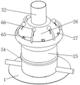
FIG. 1 is a schematic overall front view of the external structure of the present invention;
FIG. 2 is a front view of the external partial structure of the annular separating box of the present invention;
FIG. 3 is a top view of the outer portion of the filter plate according to the present invention;
FIG. 4 is a front view of the internal partial cross-sectional structure of the annular divider box of the present invention;
FIG. 5 is a schematic view of a front view of an external partial structure of a strut in accordance with the present invention;
FIG. 6 is a bottom view of an external portion of the annular aeration panel of the present invention;
FIG. 7 is a front view of an outer partial structure of the splash shield of the present invention;
fig. 8 is a bottom view of the outer part of the splash guard according to the present invention.
In the figure: 1. a filter vat; 21. an electric shaft; 22. a stirring scraper bar; 23. a semicircular diversion trench; 24. a filter plate; 25. an annular separator tank; 26. a splash guard; 27. a through hole; 31. a liquid outlet pipe; 32. a feed pipe; 41. extruding the block; 42. a traveler; 43. rotating the rod; 44. vibrating the ball; 45. a metal spring sheet; 46. a fixed block; 51. an elastic pressure plate; 52. an elastic air bag; 53. an air outlet pipe; 54. an annular vent plate; 55. filtering holes; 56. an annular triangular ring; 61. a rubber rod; 62. striking a ball; 63. an arc push rod; 64. an arc-shaped collision plate; 65. a support bar; 66. and fixing the ball.
Detailed Description
The technical solutions in the embodiments of the present invention will be clearly and completely described below with reference to the drawings in the embodiments of the present invention, and it is obvious that the described embodiments are only a part of the embodiments of the present invention, and not all of the embodiments. All other embodiments, which can be derived by a person skilled in the art from the embodiments given herein without making any creative effort, shall fall within the protection scope of the present invention.
Referring to fig. 1-8, the present invention provides a technical solution: a lithium battery recycling wastewater filtering device comprises a filtering barrel 1, a filtering mechanism is arranged in the filtering barrel 1, the filtering mechanism comprises an electric shaft 21, the electric shaft 21 is rotatably arranged on the inner wall of the filtering barrel 1, a stirring scraping rod 22 is fixedly arranged on the outer wall of the electric shaft 21, a semicircular diversion trench 23 is fixedly arranged on the stirring scraping rod 22, the bottom of the stirring scraping rod 22 is slidably arranged on the outer wall of the top of a filtering plate 24, the filtering plate 24 is fixedly arranged on the outer wall of the top of an annular separation box 25, an anti-splash cover 26 is rotatably arranged on the outer wall of the top of the annular separation box 25, a through hole 27 is fixedly arranged on the anti-splash cover 26, the filtering plate 24 is arranged in a basin shape with a small lower part and a large part, the stirring scraping rod 22 is arc-shaped and is attached to the outer wall of the filtering plate 24, a channel is formed between the semicircular diversion trench 23 and the inner wall of the through hole 27, and enables impurities on the semicircular diversion trench 23 to pass through the through hole 27, the annular separating box 25 is hollow and comprises an inner layer and an outer layer, the electric shaft 21 is positioned in the inner layer of the annular separating box 25, an inner cavity is formed between the inner layer and the outer layer of the annular separating box 25, an outer cavity is formed between the outer layer of the annular separating box 25 and the filter barrel 1, the inner layer of the annular separating box 25, the inner cavity of the annular separating box 25 and the outer cavity of the annular separating box 25 are not communicated with each other, a liquid outlet pipe 31 penetrates through and is fixedly installed at the bottom of the annular separating box 25, a feeding pipe 32 is fixedly installed at the top of the splash guard 26, through the arrangement of the filtering device, when the electric shaft 21 is started to drive the stirring scraping rod 22 to stir and filter the filter plate 24, impurities can slide outwards along the semicircular diversion groove 23 through the generated centrifugal force, and can fall into the cavity between the annular separating box 25 and the filter barrel 1 through the through hole 27 on the splash guard 26 for separation and collection, prevent the blockage of the filter plate 24 and improve the filtering efficiency.
As shown in fig. 2, 4, 5 and 6, in the present invention, a vibration device is disposed on the annular separating box 25, the vibration device includes an extrusion block 41, the extrusion block 41 is fixedly mounted on the outer wall of the electric shaft 21, a sliding column 42 is penetratingly and slidably mounted on the annular separating box 25, one end of the sliding column 42 close to the extrusion block 41 is semi-circular, one end of the sliding column 42 far from the extrusion block 41 is rotatably mounted with a rotating rod 43, a vibration ball 44 is fixedly mounted at the bottom of the rotating rod 43, two rotating rods 43 and two vibration balls 44 are disposed and vertically and symmetrically distributed with respect to the sliding column 42, the outer walls of the two rotating rods 43 are elastically connected through a metal elastic sheet 45, a fixed block 46 is fixedly mounted in the inner cavity of the annular separating box 25, the vibration ball 44 is disposed close to the outer portion of the fixed block 46, an air blowing device is disposed on the sliding column 42, the air blowing device includes an elastic pressing plate 51, the elastic pressing plate 51 is fixedly mounted on the outer wall of the metal elastic sheet 45, an elastic air bag 52 is fixedly arranged between the outer wall of the sliding column 42 and the outer wall of the elastic pressing plate 51, an air outlet pipe 53 is fixedly arranged on the outer wall of the elastic air bag 52, the output end of the air outlet pipe 53 is fixedly arranged on an annular vent plate 54, the annular vent plate 54 is fixedly arranged on the outer wall of the annular separation box 25, the output end of the annular vent plate 54 is vertically arranged downwards, a filter hole 55 is fixedly arranged on the outer wall of the bottom of the annular vent plate 54, an annular triangular ring 56 is fixedly arranged on the top of the annular vent plate 54, the annular triangular ring 56 is arranged in an inclined surface mode, through the arrangement of a vibrating device, the electric shaft 21 can drive the extrusion block 41 to rotate along with the electric shaft, the extrusion block 41 can intermittently push the sliding column 42 to slide, the sliding column 42 can drive the rotating rod 43 and the vibrating ball 44 to impact and vibrate the fixed block 46, and the vibration effect is transmitted to the annular separation box 25 to promote the downward flow of water flow on the annular separation box 25 and the falling of impurities, the filtration and separation efficiency is improved.
As shown in fig. 2, 7 and 8, in the present invention, an auxiliary device is disposed on the splash guard 26, the auxiliary device includes a rubber rod 61, the rubber rod 61 is rotatably mounted on an inner wall of a top portion of the splash guard 26, an impact ball 62 is fixedly mounted on an outer wall of the rubber rod 61, an arc push rod 63 is penetratingly and slidably mounted on the splash guard 26, a bottom portion of the arc push rod 63 is fixedly mounted on an outer wall of an arc impact plate 64, a top portion of the arc push rod 63 is configured as an arc surface, a top portion of the arc push rod 63 is elastically connected with an outer wall of the splash guard 26 through an elastic piece, a support rod 65 is fixedly mounted on an outer wall of a top portion of the annular partition box 25, a fixed ball 66 is fixedly mounted on a top portion of the support rod 65, the fixed ball 66 is disposed near the top portion of the arc push rod 63, by disposing the auxiliary device, the rubber rod 61 on the splash guard 26 can swing when the splash guard 26 rotates along with the stirring rod 22, the impact ball 62 can impact between the rubber rod 61 to generate reverse swing, the intercepting efficiency of the splash guard 26 is improved while an effective guide effect is performed on the splashed waste water and impurities.
When the stirring and filtering device is in use, when the electric shaft 21 is started to drive the stirring and scraping rod 22 to stir and filter the filter plate 24, impurities on the filter plate 24 can be cleaned through scraping of the stirring and scraping rod 22, and simultaneously after the impurities are cleaned through scraping of the stirring and scraping rod 22, the impurities can slide to the outside along the semicircular flow guide groove 23 through centrifugal force generated by rotation of the stirring and scraping rod 22, the impurities can fall into a cavity between the annular separation box 25 and the filter barrel 1 through the through hole 27 on the splash guard 26 to be separated and collected, meanwhile, the splash guard 26 can intercept waste water impurities splashed in the stirring process along with rotation of the stirring and scraping rod 22, water flow passing through the filter plate 24 can enter a cavity formed between the bottom of the filter plate 24 and the inner side outer wall of the annular separation box 25 to be collected and then flows out from the liquid outlet pipe 31, and finally, the purpose of preventing blockage of the filter plate 24 while stirring and filtering of the filter plate 24 is achieved, the filtering efficiency is improved; by arranging the vibrating device, when the electric shaft 21 rotates, the extruding block 41 can be driven to rotate along with the electric shaft, the extruding block 41 can intermittently push the sliding column 42 to slide, the sliding column 42 can drive the rotating rod 43 and the vibrating ball 44 to impact and vibrate the fixed block 46, through the elastic action of the metal elastic sheet 45, the rotating rod 43 and the vibrating ball 44 can generate the reciprocating knocking and vibrating effect on the fixed block 46, then the vibrating effect is transmitted to the annular separation box 25 to promote the downward flow of the water flow on the inner outer wall of the annular separation box 25 and the falling of impurities on the outer wall of the annular separation box 25, so as to improve the filtering and separating efficiency, through the air blowing device, when the sliding column 42 drives the rotating rod 43 to rotate due to the pushing of the extruding block 41, the sliding column 42 and the metal elastic sheet 45 can move in opposite directions, so that the sliding column 42 and the elastic pressing plate 51 can generate the compressing effect on the elastic air bag 52, the elastic air bag 52 is compressed to generate the air flow which is conveyed into the annular ventilation plate 54 through the air outlet pipe 53, the annular ventilation plate 54 can guide the airflow vertically downwards to promote the sliding of impurities on the outer wall of the annular separation box 25, so that the impurities are prevented from being attached to the outer wall of the annular separation box 25 to influence the separation and collection efficiency of the impurities, the inclined surface of the annular triangular ring 56 can prevent the impurities from sliding downwards and being blocked by the annular ventilation plate 54, and the airflow guiding effect is achieved; by arranging the auxiliary device, the rubber rod 61 on the splash guard 26 can swing when the splash guard 26 rotates along with the stirring scraper 22, the impact ball 62 can impact between the rubber rods 61 to generate reverse swing while the rubber rod 61 swings, so that the interception efficiency and the diversion effect of the splash guard 26 are improved, and simultaneously, the effective diversion effect is performed on splashed waste water and impurities, by arranging the arc push rod 63 and the arc striker 64, when the splash guard 26 rotates along with the stirring scraper 22, the arc push rod 63 can be intermittently extruded by the fixed ball 66 on the support rod 65 to generate sliding, the arc push rod 63 can push and drive the arc striker 64 to impact the rubber rod 61, so as to promote the swinging of the rubber rod 61, so that the rubber rod 61 can clear the waste water and impurities attached to the rubber rod 61, and the diversion efficiency is improved, and in conclusion, by arranging the filtering device, when starting up electronic axle 21 and driving stirring scraper bar 22 and stir filterable to filter 24, impurity alright drop to the cavity between annular separator box 25 and the filter vat 1 through-hole 27 on the splashproof cover 26 and separate the collection, can prevent filter 24's jam in the filterable time of filter 24 finally, improve filtration efficiency.
Although embodiments of the present invention have been shown and described, it will be appreciated by those skilled in the art that changes, modifications, substitutions and alterations can be made in these embodiments without departing from the principles and spirit of the invention, the scope of which is defined in the appended claims and their equivalents.
Claims (10)
1. The utility model provides a lithium cell recovery waste water filter equipment, includes filter vat (1), its characterized in that: be provided with filtering mechanism in filter vat (1), filtering mechanism includes electronic axle (21), electronic axle (21) rotates and installs on filter vat (1) inner wall, fixed mounting has the stirring to scrape pole (22) on electronic axle (21) outer wall, the stirring is scraped pole (22) and is gone up fixed semicircle guiding gutter (23) of having seted up, stirring is scraped pole (22) bottom slidable mounting on filter (24) top outer wall, filter (24) fixed mounting is on annular divider box (25) top outer wall, annular divider box (25) top outer wall rotates and installs splash guard (26), fixed through-hole (27) have been seted up on splash guard (26), stirring is scraped pole (22) and is passed through-hole (27) fixed mounting on splash guard (26).
2. The lithium battery recycling wastewater filtering device as set forth in claim 1, wherein: the filter (24) are the basin-shaped setting of big end up, the stirring is scraped pole (22) and is arc form and laminating filter (24) outer wall setting, form the passageway between semicircle guiding gutter (23) and through-hole (27) inner wall.
3. The lithium battery recycling wastewater filtering device as set forth in claim 1, wherein: annular divider box (25) are hollow form and include inlayer and skin, electronic axle (21) are located annular divider box (25) inlayer inside, form inside cavity between annular divider box (25) inlayer and the skin, form outside cavity between annular divider box (25) skin and filter vat (1), and annular divider box (25) inlayer inside, annular divider box (25) inside cavity and annular divider box (25) outside cavity each other not communicate between two liang, annular divider box (25) bottom is run through and fixed mounting has drain pipe (31), splash guard (26) top fixed mounting has inlet pipe (32).
4. The lithium battery recycling wastewater filtering device as set forth in claim 1, wherein: be provided with vibrating device on annular divider box (25), vibrating device is including extrusion piece (41), extrusion piece (41) fixed mounting is on electronic axle (21) outer wall, run through and slidable mounting has traveller (42) on annular divider box (25), the one end that traveller (42) are close to extrusion piece (41) sets up to half circular shape, the one end that traveller (42) kept away from extrusion piece (41) is rotated and is installed dwang (43).
5. The lithium battery recycling wastewater filtering device as set forth in claim 4, wherein: dwang (43) bottom fixed mounting has vibration ball (44), the quantity of dwang (43) and vibration ball (44) has two and about traveller (42) longitudinal symmetry distribute, two through metal shrapnel (45) elastic connection between dwang (43) outer wall, fixed mounting has fixed block (46) in annular divider box (25) inside cavity, vibration ball (44) are close to fixed block (46) outside setting.
6. The lithium battery recycling wastewater filtering device as set forth in claim 5, wherein: the air blowing device is arranged on the sliding column (42) and comprises an elastic pressing plate (51), the elastic pressing plate (51) is fixedly installed on the outer wall of the metal elastic sheet (45), an elastic air bag (52) is fixedly installed between the outer wall of the sliding column (42) and the outer wall of the elastic pressing plate (51), and an air outlet pipe (53) is fixedly installed on the outer wall of the elastic air bag (52).
7. The lithium battery recycling wastewater filtering device as set forth in claim 6, wherein: the output end of the air outlet pipe (53) is fixedly installed on an annular vent plate (54), the annular vent plate (54) is fixedly installed on the outer wall of the annular separation box (25), the output end of the annular vent plate (54) is vertically arranged downwards, the outer wall of the bottom of the annular vent plate (54) is fixedly provided with a filter hole (55), and the top of the annular vent plate (54) is fixedly provided with an annular triangular ring (56).
8. The lithium battery recycling wastewater filtering device as set forth in claim 1, wherein: be provided with auxiliary device on splashproof cover (26), auxiliary device includes rubber pole (61), rubber pole (61) are rotated and are installed on splashproof cover (26) top inner wall, fixed mounting has impact ball (62) on rubber pole (61) outer wall.
9. The lithium battery recycling wastewater filtering device as recited in claim 8, wherein: run through and slidable mounting has arc push rod (63) on splash guard (26), arc push rod (63) bottom fixed mounting hits on board (64) outer wall in the arc, arc push rod (63) top sets up to the arcwall face, through shell fragment elastic connection between arc push rod (63) top and splash guard (26) outer wall.
10. The lithium battery recycling wastewater filtering device as recited in claim 9, wherein: the supporting rod (65) is fixedly mounted on the outer wall of the top of the annular separating box (25), the fixing ball (66) is fixedly mounted on the top of the supporting rod (65), and the fixing ball (66) is arranged close to the top of the arc-shaped push rod (63).
Priority Applications (1)
| Application Number | Priority Date | Filing Date | Title |
|---|---|---|---|
| CN202210291606.XA CN114377453A (en) | 2022-03-24 | 2022-03-24 | Lithium cell recovery waste water filter equipment |
Applications Claiming Priority (1)
| Application Number | Priority Date | Filing Date | Title |
|---|---|---|---|
| CN202210291606.XA CN114377453A (en) | 2022-03-24 | 2022-03-24 | Lithium cell recovery waste water filter equipment |
Publications (1)
| Publication Number | Publication Date |
|---|---|
| CN114377453A true CN114377453A (en) | 2022-04-22 |
Family
ID=81205194
Family Applications (1)
| Application Number | Title | Priority Date | Filing Date |
|---|---|---|---|
| CN202210291606.XA Pending CN114377453A (en) | 2022-03-24 | 2022-03-24 | Lithium cell recovery waste water filter equipment |
Country Status (1)
| Country | Link |
|---|---|
| CN (1) | CN114377453A (en) |
Cited By (2)
| Publication number | Priority date | Publication date | Assignee | Title |
|---|---|---|---|---|
| CN118045551A (en) * | 2024-04-16 | 2024-05-17 | 四川蜀道建筑科技有限公司 | Polycarboxylate water reducing agent waste material comprehensive utilization apparatus for producing |
| CN118079509A (en) * | 2024-04-25 | 2024-05-28 | 江苏兄弟管业制造有限公司 | Filter element convenient to disassemble and assemble for filter and use method of filter element |
Citations (6)
| Publication number | Priority date | Publication date | Assignee | Title |
|---|---|---|---|---|
| CN204447485U (en) * | 2014-12-25 | 2015-07-08 | 杭州科星水处理工程有限公司 | For the agitating device of sewage disposal |
| CN207109960U (en) * | 2017-08-11 | 2018-03-16 | 神鹿环保科技(昆山)有限公司 | A kind of kitchen waste treater splash guard |
| US20200157783A1 (en) * | 2018-11-19 | 2020-05-21 | Chun Ho Yau | Wind-driven Air-Compressed Energy-Saving Collecting and Filtering Device for Field Fresh water |
| CN210751546U (en) * | 2019-10-10 | 2020-06-16 | 天津百诗特科技发展有限公司 | Special filter equipment of coating production |
| CN211189254U (en) * | 2019-08-04 | 2020-08-07 | 上海津和机械制造有限公司 | Filtering equipment for paint processing |
| CN113756397A (en) * | 2021-10-22 | 2021-12-07 | 张效文 | Secondary water supply filter equipment |
-
2022
- 2022-03-24 CN CN202210291606.XA patent/CN114377453A/en active Pending
Patent Citations (6)
| Publication number | Priority date | Publication date | Assignee | Title |
|---|---|---|---|---|
| CN204447485U (en) * | 2014-12-25 | 2015-07-08 | 杭州科星水处理工程有限公司 | For the agitating device of sewage disposal |
| CN207109960U (en) * | 2017-08-11 | 2018-03-16 | 神鹿环保科技(昆山)有限公司 | A kind of kitchen waste treater splash guard |
| US20200157783A1 (en) * | 2018-11-19 | 2020-05-21 | Chun Ho Yau | Wind-driven Air-Compressed Energy-Saving Collecting and Filtering Device for Field Fresh water |
| CN211189254U (en) * | 2019-08-04 | 2020-08-07 | 上海津和机械制造有限公司 | Filtering equipment for paint processing |
| CN210751546U (en) * | 2019-10-10 | 2020-06-16 | 天津百诗特科技发展有限公司 | Special filter equipment of coating production |
| CN113756397A (en) * | 2021-10-22 | 2021-12-07 | 张效文 | Secondary water supply filter equipment |
Cited By (3)
| Publication number | Priority date | Publication date | Assignee | Title |
|---|---|---|---|---|
| CN118045551A (en) * | 2024-04-16 | 2024-05-17 | 四川蜀道建筑科技有限公司 | Polycarboxylate water reducing agent waste material comprehensive utilization apparatus for producing |
| CN118079509A (en) * | 2024-04-25 | 2024-05-28 | 江苏兄弟管业制造有限公司 | Filter element convenient to disassemble and assemble for filter and use method of filter element |
| CN118079509B (en) * | 2024-04-25 | 2024-06-28 | 江苏兄弟管业制造有限公司 | Filter element convenient to disassemble and assemble for filter and use method of filter element |
Similar Documents
| Publication | Publication Date | Title |
|---|---|---|
| CN114377453A (en) | Lithium cell recovery waste water filter equipment | |
| CN110180638A (en) | The recyclable device of waste and old lead acid accumulator and its process flow | |
| CN210385990U (en) | Screening mechanism of waste lithium battery recovery device | |
| CN111659700A (en) | Separation device and method for lithium battery recovery | |
| CN113521845A (en) | Sponge urban rainwater treatment and recycling integrated equipment and treatment method thereof | |
| CN116037263A (en) | Waste lithium battery disassembling and recycling device and method | |
| CN117144141A (en) | Method and device for recycling lithium from waste lithium ion electrolyte | |
| CN210186492U (en) | Collecting device for lead slime of waste lead-acid storage battery | |
| CN211998986U (en) | Sludge discharge device for sewage treatment | |
| CN112093939A (en) | Spraying effluent treatment plant convenient to add medicament | |
| CN217868416U (en) | Waste water recovery processing apparatus is used in lithium electricity cathode material production | |
| CN215352129U (en) | Automatic imbibition oil-gas separation device | |
| CN214553950U (en) | Garbage disposal device for construction | |
| CN214193502U (en) | Drainage system for electroplating cylinder of centrifugal electroplating machine | |
| CN216092631U (en) | Sludge discharge device for sewage treatment | |
| CN215586603U (en) | Waste lithium battery powder separator | |
| CN213340491U (en) | Waste lithium battery all-component material separation and collection device | |
| CN220835836U (en) | Mining breaker | |
| CN219324545U (en) | Copper, aluminium grain degree of depth belt cleaning device | |
| CN212348928U (en) | Battery recovery processing device for new energy automobile | |
| CN212198587U (en) | Horizontal flow type dissolved air flotation machine | |
| CN220071847U (en) | Recycling device for waste lithium iron phosphate pole pieces | |
| CN221074216U (en) | Separation device for underground oil extraction | |
| CN217511772U (en) | Mixing arrangement of medicament for sewage treatment | |
| CN218405616U (en) | Dredging and deslagging device for hydraulic and hydroelectric engineering |
Legal Events
| Date | Code | Title | Description |
|---|---|---|---|
| PB01 | Publication | ||
| PB01 | Publication | ||
| SE01 | Entry into force of request for substantive examination | ||
| SE01 | Entry into force of request for substantive examination | ||
| RJ01 | Rejection of invention patent application after publication |
Application publication date: 20220422 |
|
| RJ01 | Rejection of invention patent application after publication |