CN114311129A - Annular production line for automobile bumpers - Google Patents
Annular production line for automobile bumpers Download PDFInfo
- Publication number
- CN114311129A CN114311129A CN202111656500.7A CN202111656500A CN114311129A CN 114311129 A CN114311129 A CN 114311129A CN 202111656500 A CN202111656500 A CN 202111656500A CN 114311129 A CN114311129 A CN 114311129A
- Authority
- CN
- China
- Prior art keywords
- feeding
- base
- movable frame
- forth
- mechanical arm
- Prior art date
- Legal status (The legal status is an assumption and is not a legal conclusion. Google has not performed a legal analysis and makes no representation as to the accuracy of the status listed.)
- Pending
Links
- 238000004519 manufacturing process Methods 0.000 title claims abstract description 20
- 238000004080 punching Methods 0.000 claims abstract description 43
- 238000003466 welding Methods 0.000 claims abstract description 43
- 230000007246 mechanism Effects 0.000 claims abstract description 36
- 210000002219 extraembryonic membrane Anatomy 0.000 claims abstract description 16
- 210000004379 membrane Anatomy 0.000 claims abstract description 16
- 239000012528 membrane Substances 0.000 claims abstract description 16
- 238000000465 moulding Methods 0.000 claims abstract description 9
- 238000012545 processing Methods 0.000 abstract description 11
- 239000000463 material Substances 0.000 abstract description 9
- 230000000694 effects Effects 0.000 abstract description 7
- 230000006872 improvement Effects 0.000 description 2
- 238000000034 method Methods 0.000 description 2
- 238000012986 modification Methods 0.000 description 2
- 230000004048 modification Effects 0.000 description 2
- 230000008569 process Effects 0.000 description 2
- 230000009286 beneficial effect Effects 0.000 description 1
- 238000005034 decoration Methods 0.000 description 1
- 230000007547 defect Effects 0.000 description 1
- 238000013461 design Methods 0.000 description 1
- 238000011161 development Methods 0.000 description 1
- 229920006351 engineering plastic Polymers 0.000 description 1
- 238000005516 engineering process Methods 0.000 description 1
- 238000003754 machining Methods 0.000 description 1
- 238000005476 soldering Methods 0.000 description 1
Images


Abstract
The invention discloses an annular production line for automobile bumpers, which comprises a base, a control cabinet, a movable frame, a tire membrane, a feeding frame, a first driving mechanism, a punching device, a feeding device and a welding device. An annular workbench is arranged on the base, and the movable frames are matched and can be movably arranged on the annular workbench back and forth around the annular workbench, and the movable frames are arranged at intervals; the moulding bed is arranged on the movable frame and moves back and forth along with the movable frame; this go up work or material rest setting on the activity machine and along with the activity of adjustable shelf back and forth, the fetal membrane that corresponds also has more stations for a plurality of on making same production line with last work or material rest, can realize the processing to a plurality of bumpers simultaneously, when installing the bumper on the fetal membrane or tearing down from the fetal membrane, it can not influence the processing of bumper on other stations, the automatic feeding of bumper accessory can be realized to loading attachment's use simultaneously, replace current artifical material loading, degree of automation is also higher.
Description
Technical Field
The invention relates to the technology of the bumper processing field, in particular to an annular production line of an automobile bumper.
Background
With the continuous improvement of living standard of people, automobiles become the most common transportation means for each family, and an automobile bumper is one of automobile external decoration parts and is a safety device for absorbing and slowing external impact force and protecting the front and the rear parts of an automobile body; with the development of the automobile industry and the extensive application of engineering plastics in the automobile industry, automobile bumpers are also moving to the way of innovation as an important safety device, and the processing mode of the bumpers is continuously improved along with the increase of the user requirements.
Current car bumper production line adds man-hour and generally adopts single station, the manual work is installed the bumper and is then driven the tool bit through the robotic arm and punch a hole respectively and weld process, still need the manual work to place accessories such as radar support and weld process after targetting in place simultaneously, not only degree of automation is not high, the cost of labor is big, and machining efficiency is lower, when the manual work is with the bumper dismouting on the fetal membrane, the arm just can't carry out the processing operation to the bumper, comparatively time-wasting cost, therefore, it is necessary to make further improvement to current bumper production line structure.
Disclosure of Invention
In view of the above, the invention provides an annular production line for automobile bumpers, which is mainly aimed at overcoming the defects in the prior art, and is characterized in that an annular workbench is arranged on a base, and a plurality of movable frames, a plurality of tire membranes and a plurality of feeding frames are correspondingly arranged, so that more stations are arranged on the same production line, the processing efficiency is greatly improved, and meanwhile, the function of automatically installing accessories is realized by matching with a feeding device, the automation degree is improved, the processing efficiency is further improved, and the labor cost is reduced.
In order to achieve the purpose, the invention adopts the following technical scheme:
an annular production line for automobile bumpers comprises a base, a control cabinet, a movable frame, a tire membrane, a feeding frame, a first driving mechanism, a punching device, a feeding device and a welding device; the base is provided with an annular workbench; the control cabinet is arranged beside the base; the movable frames can be movably arranged on the annular workbench back and forth around the annular workbench, the movable frames are arranged at intervals, and second sliding rails are arranged on the movable frames; the moulding bed is arranged on the movable frame and moves back and forth along with the movable frame; the feeding frame is arranged on the movable frame and moves back and forth along with the movable frame, a plurality of corresponding tire membranes and feeding frames are arranged on each movable frame, each movable frame is correspondingly provided with one tire membrane and one feeding frame, a sliding block matched with a second sliding rail is arranged on each feeding frame, each feeding frame is driven by a second driving mechanism to move back and forth along the second sliding rail through the matching of the sliding block and the second sliding rail, and the second driving mechanism is arranged on the base and connected with the control cabinet; the first driving mechanism is arranged on the base and drives the movable frame to move back and forth, the first driving mechanism is connected with the control cabinet, the first driving mechanism comprises a support, a motor, a screw rod and a connecting rod, the support is arranged on the base, the motor is arranged on the support and connected with the control cabinet, and the screw rod is arranged at the output end of the motor and driven by the motor to rotate back and forth; the connecting rod is sleeved on the screw rod and moves back and forth along the screw rod under the driving of the screw rod, the upper end of the connecting rod is provided with a connector matched with the movable frame, and the movable frame moves back and forth under the driving of the connecting rod. (ii) a The punching device, the feeding device and the welding device are all arranged beside the side of the base and arranged around the annular workbench in sequence, and the punching device, the feeding device and the welding device are all connected with the control cabinet.
As a preferred scheme, a fence is arranged on the periphery of the base, and the control cabinet, the movable frame, the moulding bed, the feeding frame, the first driving mechanism, the punching device, the feeding device and the welding device are all arranged in the fence.
As a preferable scheme, an annular first slide rail is arranged on the annular workbench, the movable frame is slidably mounted on the first slide rail and moves back and forth along the first slide rail, and the movable frame is pushed by the first driving mechanism to move back and forth.
Preferably, the second driving mechanism is an air cylinder.
As a preferred scheme, the punching device comprises a first controller, a die cutter magazine, a punching tool bit and a first mechanical arm; the first controller is arranged on the base and connected with the control cabinet, the punching tool magazine is arranged on the base and located beside the annular workbench, the punching tool bit can be arranged on the punching tool magazine in a pick-and-place mode, a first connecting portion connected with the free end of the first mechanical arm is arranged on the punching tool bit, the first mechanical arm is arranged beside the punching tool magazine and the annular workbench and connected with the first controller, and the free end of the first mechanical arm moves back and forth between the punching tool magazine and the fetal membrane.
Preferably, the punching devices are two and are sequentially arranged along the outer side of the annular workbench.
As a preferred scheme, the feeding device comprises a second controller, a feeding head library, a feeding head and a second mechanical arm; the second controller is arranged on the base and connected with the control cabinet, and the feeding head warehouse is arranged on the base and positioned beside the annular workbench; the feeding head is arranged on the feeding head warehouse in a pick-and-place mode, and a second connecting part connected with the free end of the second mechanical arm is arranged on the feeding head; the second mechanical arm is arranged beside the feeding head warehouse and the annular workbench and connected with the second controller, and the free end of the second mechanical arm moves back and forth among the feeding head warehouse, the feeding frame and the tire membrane.
As a preferred scheme, the welding device comprises a third controller, a welding head library, a welding head and a third mechanical arm; the third controller is arranged on the base and connected with the control cabinet, and the welding head library is arranged on the base and positioned beside the annular workbench; the welding head is arranged on the welding head library in a pick-and-place manner, and a third connecting part connected with the free end of the third mechanical arm is arranged on the welding head; the third mechanical arm is arranged beside the welding head bank and the annular workbench and is connected with a third controller, and the free end of the third mechanical arm moves back and forth between the welding head bank and the fetal membrane.
Compared with the prior art, the invention has obvious advantages and beneficial effects, and specifically, the technical scheme includes that:
an annular workbench is arranged on the base, and the movable frames are matched and can be movably arranged on the annular workbench back and forth around the annular workbench, and the movable frames are arranged at intervals; the moulding bed is arranged on the movable frame and moves back and forth along with the movable frame; this go up work or material rest setting on the activity machine and along with the activity of adjustable shelf back and forth, the fetal membrane that corresponds also has more stations for a plurality of on making same production line with last work or material rest, can realize the processing to a plurality of bumpers simultaneously, when installing the bumper on the fetal membrane or tearing down from the fetal membrane, it can not influence the processing of bumper on other stations, a large amount of time cost has been saved, the automatic feeding of bumper accessory can be realized to loading attachment's use simultaneously, replace current artifical material loading, the labor cost has not only been saved, degree of automation is also higher.
To more clearly illustrate the structural features and effects of the present invention, the present invention will be described in detail below with reference to the accompanying drawings and specific embodiments.
Drawings
FIG. 1 is a schematic perspective view of a preferred embodiment of the present invention;
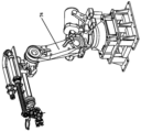
FIG. 2 is a schematic perspective view of a first robot according to a preferred embodiment of the present invention;
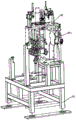
FIG. 3 is a schematic perspective view of a magazine according to a preferred embodiment of the present invention;
FIG. 4 is a schematic perspective view of a feed block magazine according to a preferred embodiment of the present invention;
FIG. 5 is a schematic perspective view of a soldering tip library according to a preferred embodiment of the present invention;
FIG. 6 is a partial assembly view of the preferred embodiment of the present invention;
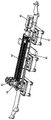
FIG. 7 is a perspective view of the first driving mechanism in accordance with the preferred embodiment of the present invention;
FIG. 8 is another partial assembly view of the preferred embodiment of the present invention.
The attached drawings indicate the following:
10. base 11, annular workstation
12. Fence 13 and first slide rail
20. Control cabinet 30 and movable frame
31. Second slide rail 40, fetal membrane
50. Feeding frame 51 and sliding block
52. Second drive mechanism 60 and first drive mechanism
61. Support 62, motor
63. Screw rod 64 and connecting rod
65. Connector 70 and punching device
71. First controller 72, die cutter tool magazine
73. Punch tool bit 731, first connecting portion
74. First mechanical arm 80 and feeding device
81. Controller 82 and feeding head warehouse
83. Feeding head 831 and second connecting part
84. Second mechanical arm 90 and welding device
91. Third controller 92 and bonding head library
93. Soldered connection 931, third connecting part
94. And a third mechanical arm.
Detailed Description
Referring to fig. 1 to 8, a specific structure of a preferred embodiment of the present invention is shown, which includes a base 10, a control cabinet 20, a movable frame 30, a tire 40, a feeding frame 50, a first driving mechanism 60, a punching device 70, a feeding device 80, and a welding device 90.
The base 10 has a ring-shaped worktable 11 thereon; in this embodiment, a fence 12 is disposed on the periphery of the base 10, and the control cabinet 20, the movable frame 30, the molding bed 40, the feeding frame 50, the first driving mechanism 60, the punching device 70, the feeding device 80, and the welding device 90 are disposed in the fence 12; an annular first slide rail 13 is arranged on the annular workbench 11.
The control cabinet 20 is disposed at a side of the base 10.
The movable frames 30 can be movably arranged on the annular workbench 11 back and forth around the annular workbench 11, and the movable frames 30 are arranged at intervals; in this embodiment, the movable frame 30 is slidably mounted on the first slide rail 13 and moves back and forth along the first slide rail 13, and the movable frame 30 is pushed by the first driving mechanism 60 to move back and forth; the movable frame 30 is provided with a second slide rail 31.
The tire membrane 40 is arranged on the movable frame 30 and moves back and forth along with the movable frame 30, and the tire membrane 40 is used for clamping the bumper clamp; the feeding frame 50 is arranged on the movable frame 30 and moves back and forth along with the movable frame 30, the feeding frame 50 is used for placing accessories such as radar brackets and the like, a plurality of corresponding tire membranes 40 and feeding frames 50 are also arranged, and each movable frame 30 is correspondingly provided with one tire membrane 40 and one feeding frame 50; in this embodiment, the feeding frame 50 is provided with a sliding block 51 engaged with the second sliding rail 31, the feeding frame 50 moves back and forth along the second sliding rail 31 under the driving of a second driving mechanism 52 through the engagement between the sliding block 51 and the second sliding rail 31, and the second driving mechanism 52 is arranged on the base 10 and connected to the control cabinet 20; the second driving mechanism 52 is a cylinder.
The first driving mechanism 60 is arranged on the base 10 and drives the movable frame 30 to move back and forth, and the first driving mechanism 60 is connected with the control cabinet 20; in this embodiment, the first driving mechanism 60 includes a bracket 61, a motor 62, a screw 63 and a connecting rod 64, the bracket 61 is disposed on the base 10, the motor 62 is disposed on the bracket 61 and connected to the control cabinet 20, the screw 63 is disposed at an output end of the motor 62 and driven by the motor 62 to rotate back and forth; the connecting rod 64 is sleeved on the screw rod 63 and moves back and forth along the screw rod 63 under the driving of the screw rod 63, the upper end of the connecting rod 64 is provided with a connecting head 65 matched with the movable frame 30, and the movable frame 30 moves back and forth under the driving of the connecting rod 64.
The punching device 70, the feeding device 80 and the welding device 90 are all arranged beside the base 10 and arranged around the annular workbench 11 in sequence, and the punching device 70, the feeding device 80 and the welding device 90 are all connected with the control cabinet 20.
In this embodiment, the punching device 70 includes a first controller 71, a die cutter magazine 72, a punching head 73, and a first robot arm 74; the first controller 71 is arranged on the base 10 and connected with the control cabinet 20, the die cutter tool magazine 72 is arranged on the base 10 and located beside the annular workbench 11, the punching tool bit 73 is arranged on the die cutter tool magazine 72 in a removable manner, the punching tool bit 73 is provided with a first connecting part 731 connected with the free end of a first mechanical arm 74, the first mechanical arm 74 is arranged beside the die cutter tool magazine 72 and the annular workbench 11 and connected with the first controller 71, and the free end of the first mechanical arm 74 moves back and forth between the die cutter tool magazine 72 and the fetal membrane 40; the punching devices 70 are two and are sequentially arranged along the outer side of the ring table 11.
The feeding device 80 comprises a second controller 81, a feeding head library 82, a feeding head 83 and a second mechanical arm 84; the second controller 81 is arranged on the base 10 and connected with the control cabinet 20, and the feeding head storeroom 82 is arranged on the base 10 and beside the annular workbench 11; the feeding head 83 is arranged on the feeding head warehouse 82 in a pick-and-place manner, and a second connecting part 831 connected with the free end of the second mechanical arm 84 is arranged on the feeding head 83; the second mechanical arm 84 is arranged beside the feeding head warehouse 82 and the annular workbench 11 and connected with the second controller 81, and the free end of the second mechanical arm 84 moves back and forth among the feeding head warehouse 82, the feeding frame 50 and the tire membranes 40.
The welding device 90 comprises a third controller 91, a welding head library 92, a welding head 93 and a third mechanical arm 94; the third controller 91 is arranged on the base 10 and connected with the control cabinet 20, and the welding head library 92 is arranged on the base 10 and beside the annular workbench 11; the welding head 93 is arranged on the welding head library 92 in a pick-and-place manner, and a third connecting part 931 connected with the free end of the third mechanical arm 94 is arranged on the welding head 93; the third robot arm 94 is disposed beside the bonding head bank 92 and the annular table 11 and connected to the third controller 91, and a free end of the third robot arm 94 is moved back and forth between the bonding head bank 92 and the green film 40.
Detailed description the working principle of the present embodiment is as follows:
during operation, a bumper is firstly placed on the tire membrane 40 from the feeding station of the annular workbench 11, the radar support is placed on the feeding frame 50, then the control cabinet 20 drives the first driving mechanism 60 to operate, so that the first driving mechanism 60 drives the movable frame 30 to move to the punching device 70 along the annular workbench 11, at this time, the first mechanical arms 74 of the two punching devices 70 are controlled by the first controller 71 to sequentially punch the bumper on the tire membrane 40 by driving the punching tool bits 73 on the punching tool magazine 72, after punching is completed, the first driving mechanism 60 continues to drive the movable frame 30 to move backwards to the feeding device 80, then the second mechanical arm 84 is controlled by the second controller 81 to sequentially mount the radar supports on the feeding frame 50 to the corresponding positions of the bumper by driving the feeding head 83 in the feeding head magazine 82, and then the first driving mechanism 60 drives the movable frame 30 to move to the welding device 90 along the annular workbench 11, at this time, the third mechanical arm 94, under the control of the third controller 91, drives the welding head 93 in the welding head library 92 to weld and fix the radar bracket in the bumper on the bumper, and after the welding is completed, the first driving mechanism 60 drives the movable frame 30 to move to the blanking station of the annular workbench 11 along the annular workbench 11, and then the machined bumper is manually removed.
The design of the invention is characterized in that: an annular workbench is arranged on the base, and the movable frames are matched and can be movably arranged on the annular workbench back and forth around the annular workbench, and the movable frames are arranged at intervals; the moulding bed is arranged on the movable frame and moves back and forth along with the movable frame; this go up work or material rest setting on the activity machine and along with the activity of adjustable shelf back and forth, the fetal membrane that corresponds also has more stations for a plurality of on making same production line with last work or material rest, can realize the processing to a plurality of bumpers simultaneously, when installing the bumper on the fetal membrane or tearing down from the fetal membrane, it can not influence the processing of bumper on other stations, a large amount of time cost has been saved, the automatic feeding of bumper accessory can be realized to loading attachment's use simultaneously, replace current artifical material loading, the labor cost has not only been saved, degree of automation is also higher.
The above description is only a preferred embodiment of the present invention, and is not intended to limit the technical scope of the present invention, so that any minor modifications, equivalent changes and modifications made to the above embodiment according to the technical spirit of the present invention are within the technical scope of the present invention.
Claims (8)
1. The utility model provides an annular production line of car bumper which characterized in that: the device comprises a base, a control cabinet, a movable frame, a moulding bed, a feeding frame, a first driving mechanism, a punching device, a feeding device and a welding device; the base is provided with an annular workbench; the control cabinet is arranged beside the base; the movable frames can be movably arranged on the annular workbench back and forth around the annular workbench, the movable frames are arranged at intervals, and second sliding rails are arranged on the movable frames; the moulding bed is arranged on the movable frame and moves back and forth along with the movable frame; the feeding frame is arranged on the movable frame and moves back and forth along with the movable frame, a plurality of corresponding tire membranes and feeding frames are arranged on each movable frame, each movable frame is correspondingly provided with one tire membrane and one feeding frame, a sliding block matched with a second sliding rail is arranged on each feeding frame, each feeding frame is driven by a second driving mechanism to move back and forth along the second sliding rail through the matching of the sliding block and the second sliding rail, and the second driving mechanism is arranged on the base and connected with the control cabinet; the first driving mechanism is arranged on the base and drives the movable frame to move back and forth, the first driving mechanism is connected with the control cabinet, the first driving mechanism comprises a support, a motor, a screw rod and a connecting rod, the support is arranged on the base, the motor is arranged on the support and connected with the control cabinet, and the screw rod is arranged at the output end of the motor and driven by the motor to rotate back and forth; the connecting rod is sleeved on the screw rod and moves back and forth along the screw rod under the driving of the screw rod, the upper end of the connecting rod is provided with a connector matched with the movable frame, and the movable frame moves back and forth under the driving of the connecting rod; the punching device, the feeding device and the welding device are all arranged beside the side of the base and arranged around the annular workbench in sequence, and the punching device, the feeding device and the welding device are all connected with the control cabinet.
2. The automotive bumper ring production line according to claim 1, characterized in that: the periphery of the base is provided with a fence, and the control cabinet, the movable frame, the moulding bed, the feeding frame, the first driving mechanism, the punching device, the feeding device and the welding device are all arranged in the fence.
3. The automotive bumper ring production line according to claim 1, characterized in that: the annular workbench is provided with an annular first sliding rail, the movable frame is slidably mounted on the first sliding rail and moves back and forth along the first sliding rail, and the movable frame is pushed by the first driving mechanism to move back and forth.
4. The automotive bumper ring production line according to claim 1, characterized in that: the second driving mechanism is a cylinder.
5. The automotive bumper ring production line according to claim 1, characterized in that: the punching device comprises a first controller, a punching tool magazine, a punching tool bit and a first mechanical arm; the first controller is arranged on the base and connected with the control cabinet, the punching tool magazine is arranged on the base and located beside the annular workbench, the punching tool bit can be arranged on the punching tool magazine in a pick-and-place mode, a first connecting portion connected with the free end of the first mechanical arm is arranged on the punching tool bit, the first mechanical arm is arranged beside the punching tool magazine and the annular workbench and connected with the first controller, and the free end of the first mechanical arm moves back and forth between the punching tool magazine and the fetal membrane.
6. The automotive bumper ring production line according to claim 1, characterized in that: the punching devices are two and are sequentially arranged along the outer side of the annular workbench.
7. The automotive bumper ring production line according to claim 1, characterized in that: the feeding device comprises a second controller, a feeding head library, a feeding head and a second mechanical arm; the second controller is arranged on the base and connected with the control cabinet, and the feeding head warehouse is arranged on the base and positioned beside the annular workbench; the feeding head is arranged on the feeding head warehouse in a pick-and-place mode, and a second connecting part connected with the free end of the second mechanical arm is arranged on the feeding head; the second mechanical arm is arranged beside the feeding head warehouse and the annular workbench and connected with the second controller, and the free end of the second mechanical arm moves back and forth among the feeding head warehouse, the feeding frame and the tire membrane.
8. The automotive bumper ring production line according to claim 1, characterized in that: the welding device comprises a third controller, a welding head library, a welding head and a third mechanical arm; the third controller is arranged on the base and connected with the control cabinet, and the welding head library is arranged on the base and positioned beside the annular workbench; the welding head is arranged on the welding head library in a pick-and-place manner, and a third connecting part connected with the free end of the third mechanical arm is arranged on the welding head; the third mechanical arm is arranged beside the welding head bank and the annular workbench and is connected with a third controller, and the free end of the third mechanical arm moves back and forth between the welding head bank and the fetal membrane.
Priority Applications (1)
| Application Number | Priority Date | Filing Date | Title |
|---|---|---|---|
| CN202111656500.7A CN114311129A (en) | 2021-12-31 | 2021-12-31 | Annular production line for automobile bumpers |
Applications Claiming Priority (1)
| Application Number | Priority Date | Filing Date | Title |
|---|---|---|---|
| CN202111656500.7A CN114311129A (en) | 2021-12-31 | 2021-12-31 | Annular production line for automobile bumpers |
Publications (1)
| Publication Number | Publication Date |
|---|---|
| CN114311129A true CN114311129A (en) | 2022-04-12 |
Family
ID=81018207
Family Applications (1)
| Application Number | Title | Priority Date | Filing Date |
|---|---|---|---|
| CN202111656500.7A Pending CN114311129A (en) | 2021-12-31 | 2021-12-31 | Annular production line for automobile bumpers |
Country Status (1)
| Country | Link |
|---|---|
| CN (1) | CN114311129A (en) |
Cited By (1)
| Publication number | Priority date | Publication date | Assignee | Title |
|---|---|---|---|---|
| CN114799625A (en) * | 2022-04-13 | 2022-07-29 | 长江智能科技(广东)股份有限公司 | Welding production line for automobile internal and external ornaments with tire house |
Citations (9)
| Publication number | Priority date | Publication date | Assignee | Title |
|---|---|---|---|---|
| DE102008061299A1 (en) * | 2007-12-13 | 2009-06-18 | Plastal Gmbh | Punching machine with flexible processing unit |
| CN202367036U (en) * | 2011-12-27 | 2012-08-08 | 延锋彼欧汽车外饰系统有限公司 | Bumper punching and radar supporting integrated tooling equipment |
| CN204077543U (en) * | 2014-07-16 | 2015-01-07 | 必诺机械(东莞)有限公司 | A kind of radar supports installs alignment device |
| CN104526361A (en) * | 2014-12-29 | 2015-04-22 | 重庆威诺克智能装备股份有限公司 | Rotary-type flexible manufacturing system and continuous production method thereof |
| CN204913275U (en) * | 2015-07-31 | 2015-12-30 | 湖北机电院装备制造有限责任公司 | Car bumper punches and automatic all -in -one of radar scaffold weldment |
| CN109514275A (en) * | 2018-12-29 | 2019-03-26 | 长江超声智能装备(广东)股份有限公司 | Bumper assembly punching weldering automatic one machine |
| CN110817314A (en) * | 2019-11-20 | 2020-02-21 | 余姚泰速自动化科技有限公司 | Multi-station annular workbench for fast switching clamping fixture modules |
| CN211682482U (en) * | 2019-12-25 | 2020-10-16 | 湖北机电院装备制造有限责任公司 | Bumper punches a hole and installs radar support's integration tool equipment |
| CN113602789A (en) * | 2021-09-06 | 2021-11-05 | 长江智能科技(广东)股份有限公司 | Fetal membrane moving tool for man-machine cooperation bumper intelligent production line |
-
2021
- 2021-12-31 CN CN202111656500.7A patent/CN114311129A/en active Pending
Patent Citations (9)
| Publication number | Priority date | Publication date | Assignee | Title |
|---|---|---|---|---|
| DE102008061299A1 (en) * | 2007-12-13 | 2009-06-18 | Plastal Gmbh | Punching machine with flexible processing unit |
| CN202367036U (en) * | 2011-12-27 | 2012-08-08 | 延锋彼欧汽车外饰系统有限公司 | Bumper punching and radar supporting integrated tooling equipment |
| CN204077543U (en) * | 2014-07-16 | 2015-01-07 | 必诺机械(东莞)有限公司 | A kind of radar supports installs alignment device |
| CN104526361A (en) * | 2014-12-29 | 2015-04-22 | 重庆威诺克智能装备股份有限公司 | Rotary-type flexible manufacturing system and continuous production method thereof |
| CN204913275U (en) * | 2015-07-31 | 2015-12-30 | 湖北机电院装备制造有限责任公司 | Car bumper punches and automatic all -in -one of radar scaffold weldment |
| CN109514275A (en) * | 2018-12-29 | 2019-03-26 | 长江超声智能装备(广东)股份有限公司 | Bumper assembly punching weldering automatic one machine |
| CN110817314A (en) * | 2019-11-20 | 2020-02-21 | 余姚泰速自动化科技有限公司 | Multi-station annular workbench for fast switching clamping fixture modules |
| CN211682482U (en) * | 2019-12-25 | 2020-10-16 | 湖北机电院装备制造有限责任公司 | Bumper punches a hole and installs radar support's integration tool equipment |
| CN113602789A (en) * | 2021-09-06 | 2021-11-05 | 长江智能科技(广东)股份有限公司 | Fetal membrane moving tool for man-machine cooperation bumper intelligent production line |
Cited By (1)
| Publication number | Priority date | Publication date | Assignee | Title |
|---|---|---|---|---|
| CN114799625A (en) * | 2022-04-13 | 2022-07-29 | 长江智能科技(广东)股份有限公司 | Welding production line for automobile internal and external ornaments with tire house |
Similar Documents
| Publication | Publication Date | Title |
|---|---|---|
| CN107030778B (en) | Flowerpot automatic punching trimming equipment | |
| US7325581B2 (en) | Apparatus for punching and welding or bonding workpieces | |
| CN218477143U (en) | Annular production line for automobile bumpers | |
| CN114311129A (en) | Annular production line for automobile bumpers | |
| CN109795127B (en) | Robot automatic impact welding quick-change equipment and machining method | |
| CN209773950U (en) | Special machine processing line for vehicle door hinge vehicle body parts | |
| CN110587109A (en) | Flexible welding machine tool for automotive interior parts | |
| CN211589000U (en) | Flexible cabin automatic welding line | |
| CN212239324U (en) | Full-automatic cutting machining device for handle gear | |
| CN211028811U (en) | Automatic assembling clamp for hydraulic oil cylinders | |
| CN210476229U (en) | Vertical numerically controlled fraise machine | |
| CN110977262A (en) | Flexible cabin automatic welding line and welding method thereof | |
| CN108161405B (en) | Assembly workstation of servo driver shell | |
| CN112122924B (en) | Flexible impact welding integrated machine for automobile bumper | |
| CN113547622B (en) | Blank body batch trimming device for ceramic processing | |
| CN212665296U (en) | Power bottom plate welding position device and system | |
| CN211276955U (en) | Flexible welding machine tool for automotive interior parts | |
| CN210587985U (en) | Automatic assembling equipment for adjusting joint assembly | |
| CN208960712U (en) | A kind of metal plate flanging production line | |
| CN214162050U (en) | Punching welding device suitable for processing automobile bumper | |
| CN111974892A (en) | Automatic feeding device of punching machine tool | |
| CN214024721U (en) | A unloading mechanism in cnc engraving and milling machine high efficiency for cell-phone shell | |
| CN213729613U (en) | Numerical control machine tool for line rail of flat machine tool body | |
| CN207057900U (en) | Cabin floor three-dimensional workstation system | |
| CN220533486U (en) | Automobile bumper impact welding integrated device |
Legal Events
| Date | Code | Title | Description |
|---|---|---|---|
| PB01 | Publication | ||
| PB01 | Publication | ||
| SE01 | Entry into force of request for substantive examination | ||
| SE01 | Entry into force of request for substantive examination |