CN114290215B - Polishing and grinding machine for processing accessories of curtain rods - Google Patents
Polishing and grinding machine for processing accessories of curtain rods Download PDFInfo
- Publication number
- CN114290215B CN114290215B CN202111651011.2A CN202111651011A CN114290215B CN 114290215 B CN114290215 B CN 114290215B CN 202111651011 A CN202111651011 A CN 202111651011A CN 114290215 B CN114290215 B CN 114290215B
- Authority
- CN
- China
- Prior art keywords
- filter
- dust
- polishing
- box
- filtering
- Prior art date
- Legal status (The legal status is an assumption and is not a legal conclusion. Google has not performed a legal analysis and makes no representation as to the accuracy of the status listed.)
- Active
Links
Images


Classifications
-
- Y—GENERAL TAGGING OF NEW TECHNOLOGICAL DEVELOPMENTS; GENERAL TAGGING OF CROSS-SECTIONAL TECHNOLOGIES SPANNING OVER SEVERAL SECTIONS OF THE IPC; TECHNICAL SUBJECTS COVERED BY FORMER USPC CROSS-REFERENCE ART COLLECTIONS [XRACs] AND DIGESTS
- Y02—TECHNOLOGIES OR APPLICATIONS FOR MITIGATION OR ADAPTATION AGAINST CLIMATE CHANGE
- Y02P—CLIMATE CHANGE MITIGATION TECHNOLOGIES IN THE PRODUCTION OR PROCESSING OF GOODS
- Y02P70/00—Climate change mitigation technologies in the production process for final industrial or consumer products
- Y02P70/10—Greenhouse gas [GHG] capture, material saving, heat recovery or other energy efficient measures, e.g. motor control, characterised by manufacturing processes, e.g. for rolling metal or metal working
Abstract
The application relates to a polishing and grinding machine for processing curtain rod accessories, and relates to the field of polishing and grinding equipment. It includes the burnishing machine body, the box, slagging-off subassembly and circulation subassembly, the burnishing machine body just is used for polishing the curtain pole accessory with box external connection, the slagging-off subassembly includes the filter residue pond, store up slag bath and scraping dust board, the filter residue pond is located the box inside and is connected with the box, store up slag bath and box outer wall connection and with filter residue pond intercommunication, be equipped with first slider between scraping dust board and the box, the scraping dust board is through first slider and box sliding connection, the scraping dust board just is arranged in scraping the dust in the filter residue pond to storing up slag bath with filter residue pond sliding connection, can dismantle in the storage slag bath and be connected with the filter residue box, the circulation subassembly is connected and communicates with the filter residue pond, the circulation subassembly is arranged in will filtering the slag bath hydrologic cycle to burnishing machine body department and spray the dust removal to the dust. This application has the effect that improves burnishing and polishing machine's work efficiency.
Description
Technical Field
The application relates to the field of polishing and grinding equipment, in particular to a polishing and grinding machine for processing accessories of a curtain rod.
Background
After the fittings of the curtain rod are processed, some burrs or bulges exist on the surface, so that small bulges or burrs in the fittings of the curtain rod need to be polished.
The existing polishing machine can generate a large amount of dust in the polishing operation process, the dust generated by processing is discharged under the action of water flow after wet dust removal is carried out through a spraying device in the polishing machine, if the dust blocks a water pipeline in the polishing machine, the polishing machine needs to be stopped to process the dust in the polishing machine, the normal processing operation of an operator is influenced, and therefore the working efficiency of the polishing machine is reduced.
Disclosure of Invention
In order to improve the work efficiency of burnishing and polishing machine, this application provides a be used for processing curtain pole accessory polishing polisher.
The application provides a be used for processing curtain pole accessory polishing polisher adopts following technical scheme:
the utility model provides a be used for processing curtain pole accessory polishing polisher, includes burnishing machine body, box, slagging-off subassembly and circulation subassembly, the burnishing machine body with box external connection just is used for polishing the curtain pole accessory and handles, the slagging-off subassembly includes filter pool, storage pool and scraping dust board, the filter pool be located inside the box and with the box is connected, the storage pool with box outer wall connection and with filter pool intercommunication, scrape dust board with be equipped with first slider between the box, it passes through to scrape dust board first slider with box sliding connection, scrape dust board with filter pool sliding connection just is arranged in scraping the dust in the filter pool extremely in the storage pool, can dismantle in the storage pool and be connected with the filter box, the circulation subassembly with filter pool connects and communicates, the circulation subassembly be used for with water circulation in the filter pool extremely burnishing machine body department sprays the dust removal to the dust.
Through adopting the above technical scheme, when processing curtain rod accessory, the dust after the processing is carried by water through the spray set of burnishing machine body and is got into in the filter slag pond, the dust forms the sediment gradually and remains in the filter slag pond, and when clearing up the residue after the sediment, only need laminate scraper filter residue bottom of the pool wall, and make the scraper remove to the storage slag pond through first slider, alright in order to clear up the dust of sediment to the storage slag pond, and can dismantle in the storage slag pond and be connected with the filter slag box, convenient from the outside is to the dust clearance of sediment, water after the processing can be by cyclic assembly cyclic utilization, the utilization ratio of the water resource has been improved, whole dust disposal process need not shut down the burnishing and burnishing machine, the work efficiency of burnishing and burnishing machine has been improved.
Optionally, the bottom plate in filter residue pond is equipped with a plurality of wavy beads, the bead along length direction with the storage tank is connected, the scraper is close to filter residue bottom of the pool wall one end with the laminating of filter residue bottom of the pool wall.
Through adopting above-mentioned technical scheme, when the water that has the dust from burnishing machine body one side inflow filter residue pond in, the formation that the rivers that have the dust can accelerate the sediment through wavy bead, is favorable to carrying out prefilter to the water in the filter residue pond, and the fitting of dust scraper and filter residue bottom of the pool wall, conveniently scrapes the sediment dust in the filter residue pond to the storage slag pond in, has improved the suitability of dust scraper.
Optionally, first slider includes guide bar, lead screw and first driving piece, the guide bar is worn to establish both ends all with box inner wall connection behind the scraping dirt board, the scraping dirt board is followed guide bar length direction with guide bar sliding connection, the lead screw is worn to establish behind the scraping dirt board with scraping dirt board threaded connection, the lead screw both ends with the box rotates to be connected, first driving piece stiff end with the box is connected, the rotation end of first driving piece with lead screw fixed connection.
Through adopting above-mentioned technical scheme, when needs clear up the dust in the filter residue pond, drive first driving piece, first driving piece drives the lead screw and rotates, and the lead screw drives the scraper and removes along protruding length direction, and guide bar and scraper sliding connection can play the guide effect to the scraper, have reduced the scraper and have taken place the slope or with the possibility that the filter residue pond breaks away from.
Optionally, still include filtering component, filtering component includes gate, filtration passageway, filter screen, expansion pipe, second driving piece and valve, filter the passageway with the filter residue pond is connected and is linked together, the gate with filter passageway sliding connection and be used for closing filter the passageway, the filter screen is located filter the passageway with between the expansion pipe and with the connection can be dismantled to the expansion pipe, the expansion pipe with the circulation subassembly is connected and is linked together, second driving piece stiff end with the circulation subassembly is connected, the expansion pipe is made by flexible material, the expansion end of second driving piece with the expansion pipe is close to filter screen one end is connected, the second driving piece is used for the drive the expansion pipe mouth of pipe with the filter screen laminating and with filter the passageway intercommunication, the valve is located the expansion pipe with between the circulation subassembly.
Through adopting above-mentioned technical scheme, when the water in the filter residue pond gets into the circulation subassembly, can filter the water in the filter residue pond through the filter screen, when needs change the filter screen, at first insert the gate in filtering the passageway, rivers when in the movable tube are gone into the back in the circulation subassembly, the valve is closed again, start the second driving piece and make the movable tube break away from with filtering the passageway, dismantle the filter screen and change clean filter screen, change the completion after, restart the second driving piece and make movable tube and filtering the passageway butt joint, whole filter screen is changed and need not shut down the change, and it is convenient fast to change, the work efficiency of the burnishing machine of polishing has been improved.
Optionally, the filtering component still includes the filter stand, the filter stand is equipped with two at least mounting grooves that are used for the installation the filter screen, the filter stand is located filter the passageway with between the movable tube, the filter stand with filter the passageway with the movable tube all is equipped with the sealing member to the kneck, works as the sealing member is used for right filter the passageway with the intercommunication of movable tube plays sealed effect, filter the stand with be equipped with the second slider between the box, filter the stand through the second slider along perpendicular filter the passageway the direction with box sliding connection.
Through adopting above-mentioned technical scheme, when the filter screen needs to be changed, start the second driving piece and make movable pipe break away from with filtering the passageway, remove the filter stand again, filter stand can install two filter screens at least, can remove to filtering in the middle of passageway and the movable pipe clean filter screen, restart the second driving piece, make in the filter stand clean filter screen by the centre gripping between filtering passageway and movable pipe, the sealing member that filters the setting of stand both sides has improved the filter stand and has filtered the leakproofness between passageway and the movable pipe.
Optionally, the second slider includes backup pad and slider, backup pad one end with box outer wall fixed connection, the backup pad is along perpendicular filter the passageway direction and has seted up the spout, the slider be arranged in the spout and along spout length direction with box sliding connection, the boss that the sealing member was the preparation of elasticity material, the boss respectively with filter the passageway with the mouth of pipe joint of activity pipe, filter the frame with the slider slip rotates the connection, the axis of rotation with spout length direction is parallel.
Through adopting the above technical scheme, when removing the filter stand, the activity pipe breaks away from with the filter stand, it keeps away from the rotation of filtration passageway direction around its rotation axial to cross the filter stand again, make the boss break away from with filtration passageway, then promote to cross the filter stand and make the filter stand slide along the spout, at this moment, clean filter screen is removed to filtering between passageway and the activity pipe, will cross filter stand and filtration passageway joint again, and start the second driving piece and make activity pipe and cross the filter stand joint, whole filter screen replacement process is convenient fast, need not shut down, the work efficiency of burnishing and polishing machine has been improved, the filter screen need not dismantle, can directly with water treat the filter screen of clearance wash can, so that reuse next time, the suitability of filter screen is improved.
Optionally, the circulation subassembly includes cistern, water pump and outlet pipe, the cistern with movable union coupling and intercommunication, the water pump is arranged in the cistern and is arranged in taking out the outlet pipe with the water in the cistern, outlet pipe one end with the water pump is connected, the other end with this body coupling of burnishing machine just is used for spraying the dust that polishing process produced.
Through adopting above-mentioned technical scheme, after water after filtering got into the cistern, the water pump can pass through the outlet pipe with the water in the cistern and transport once more to burnishing machine body department and carry out wet dedusting, improved the utilization ratio of water resource, the cistern can save filterable water moreover, and after the valve was closed, the water pump still can continuous work, has improved the work efficiency of burnishing and burnishing machine.
Optionally, still include dust absorption assembly, dust absorption assembly includes the suction hood, goes out tuber pipe, fan and filter core, the suction hood with the box is connected and is communicate, the suction hood is located box top and upper end throat, it is located to go out the tuber pipe the suction hood top and with the suction hood is connected and is communicated, the filter core is located go out in the tuber pipe and with it can dismantle the connection to go out the tuber pipe, the fan with go out tuber pipe connection and intercommunication.
Through adopting above-mentioned technical scheme, when the accessory of burnishing machine body to the curtain pole is polished, a small amount of dust is not purified by the spray assembly of burnishing machine body in addition, the fan can adsorb the dust in the air this moment, and make the dust enter into the box, the possibility that the dust caused the injury to the staff has been reduced, the suitability of burnishing and polishing machine has been improved, suction hood upper end throat is favorable to improving the velocity of flow of air, make the air in the box be taken away fast, and the filter core can filter the air in the box, the dust is discharged to the sky possibility that causes the pollution has been reduced.
In summary, the present application includes at least one of the following beneficial technical effects:
1. the residue removing component is arranged, the residue filtering pool of the residue removing component is positioned inside the box body and connected with the box body, the residue storage pool is positioned outside the box body, the dust scraping plate scrapes precipitated dust in the residue filtering pool to the residue filtering box in the residue filtering pool through the first sliding part, so that the dust is convenient to collect and clean, when the whole polishing machine is used for treating the dust, the machine does not need to be stopped to clean the precipitated dust in the residue filtering pool, and the working efficiency of the polishing machine is improved;
2. the bottom plate of the residue filtering tank is provided with a plurality of wavy convex edges, water flow with dust can collide with the wavy convex edges, the dust can be accelerated to form precipitate after multiple collisions, preliminary purification of the water with the dust is facilitated, the precipitated dust can slide to the residue storing tank along the groove between the adjacent convex edges under the action of the dust scraping plate, and the dust cleaning efficiency is improved;
3. the filter component further comprises a filter frame, the filter frame is at least provided with two mounting grooves for mounting the filter screen, bosses made of elastic materials are arranged on the two sides of the vertical filter screen, the filter frame is conveniently and closely clamped with the filter channel and the movable pipe respectively, the mounting sealing performance of the filter screen is improved, the filter screen is simply and conveniently replaced without being stopped, and the working efficiency of the polishing machine is improved.
Drawings
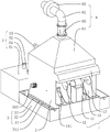
Fig. 1 is a schematic perspective view of a polishing and grinding machine for processing a curtain rod accessory according to an embodiment of the present disclosure;
fig. 2 is a schematic perspective view of another perspective view of a polishing and grinding machine for manufacturing a curtain rod accessory according to an embodiment of the present disclosure;
fig. 3 is a schematic perspective view of a protruding display box inside of a polishing and grinding machine for processing a curtain rod accessory according to an embodiment of the present application;
fig. 4 is a partially exploded view of a highlighted filter assembly in a polishing sander for machining a curtain rod accessory according to an embodiment of the present application.
Description of reference numerals: 1. a polishing machine body; 11. a double-headed motor; 12. a polishing pad; 13. a baffle plate; 14. a water dripping plate; 141. a flow port; 15. a shower pipe; 2. a box body; 3. a deslagging assembly; 31. a slag filtering tank; 311. a rib; 32. a slag storage tank; 33. a slag box; 34. a dust scraping plate; 35. a first slider; 351. a guide bar; 352. a lead screw; 353. a first driving member; 4. a filter assembly; 41. a filtration channel; 42. a gate; 43. a filter screen; 44. a movable tube; 45. a valve; 46. a second slider; 461. a support plate; 462. a slider; 463. a chute; 47. a filter frame; 471. mounting grooves; 472. a boss; 48. a second driving member; 5. a circulation component; 51. a reservoir; 52. a water pump; 53. a water outlet pipe; 54. an air inlet pipe; 6. a dust collection assembly; 61. a dust hood; 62. an air outlet pipe; 63. a fan; 64. a filter element; 65. a movable door.
Detailed Description
The present application is described in further detail below with reference to figures 1-4.
The embodiment of the application discloses a polishing and grinding machine for machining accessories of a curtain rod. Referring to fig. 1 and 2, a polishing and grinding machine for processing curtain rod accessories includes a polishing machine body 1, a box 2, a residue removing component 3, a filtering component 4, a circulating component 5 and a dust collecting component 6, the polishing machine body 1 is connected with the box 2 and is used for polishing and grinding the curtain rod accessories, the residue removing component 3 is connected with the box 2 and is used for collecting and processing dust processed by polishing and grinding, the filtering component 4 is connected with and communicates with the box 2, the filtering component 4 is used for filtering water after wet dust removal, the circulating component 5 is connected with the box 2 and is used for circulating the filtered water to the polishing machine body 1 for wet dust removal, and the dust collecting component 6 is connected with the box 2 and is used for adsorbing dust in the air to the box 2 for reprocessing.
When the accessory to the curtain pole is processed, at first place burnishing machine body 1 department with the accessory and carry out the burnishing and polishing processing, the dust that the burnishing and polishing produced is sprayed the purification by the water that conveys among the circulation subassembly 5, surplus dust in the air is absorbed to the box 2 in by dust absorption subassembly 6, the dust gets into and is collected the processing through deslagging subassembly 3 after in the box 2, water among the deslagging subassembly 3 is sent to and is recycled among the circulation subassembly 5 after being filtered by filter assembly 4, whole in-process deslagging subassembly 3 can clear up the residue that gets into among the burnishing machine body 1 under the circumstances of not shutting down, the work efficiency of burnishing and polishing machine has been improved.
Referring to fig. 1 and 3, the polishing machine body 1 includes a double-headed motor 11, a polishing pad 12, a baffle 13, a water flowing plate 14 and a spray pipe 15, a shell of the double-headed motor 11 is connected with an outer wall of the box body 2 through a bolt, the polishing pad 12 has two rotating ends which are respectively connected with the double-headed motor 11 through a nut fixed connection, the baffle 13 covers the top end of the double-headed motor 11 and one side of the baffle 13 is connected with the outer wall of the box body 2 integrally, the water flowing plate 14 has two rotating ends which are symmetrically arranged about the double-headed motor 11, the water flowing plate 14 is respectively connected with the side wall of the box body 2 close to one end of the double-headed motor 11 through a bolt, the water flowing plate 14 is arc-shaped and is provided with a flow opening 141 in the middle, the flow opening 141 is communicated with the box body 2, the spray pipe 15 is located above the water flowing plate 14 and is connected with the box body 2 through a bolt, and the spray pipe 15 is connected with the circulating assembly 5 and is communicated.
When the accessories are ground, firstly, water in the circulating component 5 is introduced into the spray pipe 15, so that the water in the spray pipe 15 flows down along the arc surface of the water flowing plate 14, at the moment, the double-end motor 11 is started, the polishing pad 12 rotates and polishes small burrs on the curtain rod accessories, most of dust generated during polishing flies to the flow opening 141 of the water flowing plate 14, the dust flows into the deslagging component 3 from the flow opening 141 after being fully contacted with the water, a small amount of dust also enters the box body 2 from the flow opening 141 under the action of the dust collection component 6 to be collected, and the whole grinding and polishing process is subjected to wet dust removal, so that the possibility of damage of the dust to workers is reduced.
As shown in fig. 2 and fig. 3, the residue removing assembly 3 includes a residue filtering pool 31, a residue storage pool 32, a residue filtering box 33, a dust scraping plate 34 and a first sliding member 35, the residue filtering pool 31 is located inside the box body 2 and connected with the box body 2, the bottom wall of the residue filtering pool 31 is provided with a plurality of wavy convex ribs 311, and the length direction of the convex ribs 311 is perpendicular to the opening direction of the flow port 141; the bottom wall of the dust scraping plate 34 close to the filter residue pool 31 is also wavy, the bottom wall of the dust scraping plate 34 is attached to the top wall of the filter residue pool 31, the length direction of the dust scraping plate 34 is perpendicular to the length direction of the convex rib 311, and the dust scraping plate 34 is connected with the box body 2 in a sliding mode along the length direction of the convex rib 311 through a first sliding piece 35; store up the sediment pond 32 and be located 2 outsidess of box and communicate with filter residue pond 31, store up the sediment pond 32 and have two and lie in filter residue pond 31 both sides respectively along bead 311 length direction, filter residue box 33 has two and lies in storage residue pond 32 respectively, filter residue box 33 is connected with the joint otic placode along length direction both sides an organic whole, filter residue box 33 passes through joint otic placode and storage residue pond 32 joint, and filter residue box 33 diapire is equipped with the filtration pore, scrape during dust board 34 is arranged in scraping filter residue box 33 with the sediment dust in filter residue pond 31.
When water with dust flows into the filter residue tank 31 from the circulation port 141, the water with dust collides with the wavy convex edge 311, multiple collisions can accelerate the dust to form precipitate, which is beneficial to preliminary purification of the water with dust, the precipitated dust falls into the groove of the wavy convex edge 311, at the moment, the dust scraping plate 34 moves along the length direction of the convex edge 311 through the first sliding part 35, so that the precipitated dust in the filter residue tank 31 is scraped into the filter residue box 33 in the filter residue tank 32, when dust and residue need to be poured, the clamping lug plate of the filter residue box 33 is detached from the filter residue tank 32, the water in the filter residue box 33 can leak from the filtering hole on the bottom wall, so that the residue is left in the filter residue box 33, the precipitated dust in the whole box body 2 does not need to be stopped during cleaning, the cleaning is simple and convenient, and the working efficiency of the polishing machine is improved.
Referring to fig. 1, fig. 2 and fig. 3, the first sliding member 35 includes a guide rod 351, a lead screw 352 and a first driving member 353, the guide rod 351 perpendicularly penetrates through the inner wall of the box 2 and is welded to both ends of the rear end of the dust scraping plate 34, the lead screw 352 penetrates through the inner wall of the box 2 and is connected to both ends of the rear end of the dust scraping plate 34 through a bearing in a rotating manner, the lead screw 352 is parallel to the guide rod 351, the lead screw 352 is in threaded connection with the dust scraping plate 34, the first driving member 353 is a motor, an outer shell of the first driving member 353 is connected to the outer wall of the box 2 through a bolt, and a driving shaft of the first driving member 353 is coaxially connected to the lead screw 352 through a coupling. When the sediment dust in the filter residue pond 31 needs to be cleared up, drive first driving piece 353, first driving piece 353 drives lead screw 352 to rotate, the length direction that makes the scraper 34 can follow lead screw 352 removes, guide bar 351 can play the guide effect to the removal of scraper 34, scraper 34 can remove repeatedly along the length direction of guide bar 351 under the effect of first driving piece 353, make the sediment dust in the filter residue pond 31 scraped to the filter residue box 33 in, the clearance has been made things convenient for, the suitability of the polishing machine has been improved.
Referring to fig. 2 and 4, the filtering assembly 4 includes a filtering channel 41, a gate 42, a filtering net 43, a movable pipe 44 and a valve 45, the filtering channel 41 is integrally connected and communicated with the residue filtering tank 31, the gate 42 is vertically inserted in the filtering channel 41 and is slidably connected with the filtering channel 41, the filtering net 43 is located between the filtering channel 41 and the movable pipe 44, the filtering net 43 is detachably connected with the movable pipe 44, the filtering channel 41 is connected and communicated with the movable pipe 44, the movable pipe 44 is connected and communicated with the circulating assembly 5, and the valve 45 is installed on the movable pipe 44. The water that filter assembly 4 is arranged in the filter residue pond 31 filters, make the water after filtering circulate and utilize in 5 flow direction shower pipes 15 of circulation subassembly again, the utilization ratio of water resource has been improved, when the filter screen 43 that needs to be changed, at first close gate 42, make the rivers in the movable tube 44 to circulation subassembly 5, close valve 45 again, dismantle movable tube 44 and filtration passageway 41, and change clean filter screen 43, it need not shut down and goes on to change filter screen 43, the work efficiency of the burnishing and polishing machine has been improved.
Referring to fig. 2 and 4, the filter assembly 4 further includes a filter frame 47, a second sliding member 46, and a second driving member 48, the filter frame 47 is provided with at least two mounting slots 471 for mounting the filter screen 43, the number of the mounting slots 471 is two, three, or four, but the number of the mounting slots 471 is only two to achieve the effect of mounting the filter screen 43, in this embodiment, the number of the mounting slots 471 is two; the two filter screens 43 are arranged along the length direction of the filter frame 47, the filter frame 47 is positioned between the filter channel 41 and the movable pipe 44, and a sealing element is also bonded at the position where the filter screens 43 are arranged on the filter frame 47, and is a boss 472 made of rubber; the boss 472 is respectively clamped with the filtering channel 41 and the opening of the movable tube 44, the movable tube 44 is made of flexible material, and the opening of the movable tube 44 is made of iron material; the second driving element 48 is a cylinder, the housing of the second driving element 48 is fixedly connected with the circulating assembly 5 through bolts, and the telescopic end of the second driving element 48 is welded with the pipe orifice of the movable pipe 44.
Referring to fig. 4, the second sliding member 46 includes a supporting plate 461 and a sliding block 462, one end of the supporting plate 461 is welded to the box 2, the other end is located below the filtering rack 47, the supporting plate 461 is provided with a sliding slot 463 along the direction perpendicular to the filtering passage 41, the sliding block 462 is located in the sliding slot 463 and is slidably connected to the supporting plate 461 along the length direction of the sliding slot 463, the sliding block 462 is hinged to the bottom wall of the filtering rack 47, and the axial direction of the hinge shaft is parallel to the length direction of the sliding slot 463.
When the filter screen 43 is replaced and cleaned, the gate 42 and the valve 45 are firstly closed, the second driving part 48 is driven, the movable pipe 44 moves towards the direction away from the filter channel 41, the movable pipe 44 is separated from the filter frame 47, the support frame rotates around the rotation axis of the support frame and the sliding block 462 to the side away from the filter channel 41, the filter frame 47 is separated from the filter channel 41, the filter frame 47 is slid, the clean filter screen 43 is positioned between the filter channel 41 and the movable pipe 44, the filter frame 47 is rotated to the clamping position of the boss 472 and the filter channel 41, the second driving part 48 is started, the movable pipe 44 is clamped with the boss 472 on the filter frame 47, the boss 472 on the filter frame 47 can play a sealing role in the butt joint of the filter channel 41 and the movable pipe 44, the applicability of the filter frame 47 is improved, the filter screen 43 to be cleaned can be washed by water so as to be replaced and used next time, the filter screen 43 can be replaced and replaced quickly, the replacement process is simple and convenient, the filter screen 43 does not need to be stopped, and the polishing applicability of the polishing machine is improved.
Referring to fig. 2 and 3, the circulation assembly 5 includes a reservoir 51, a water pump 52 and a water outlet pipe 53, the reservoir 51 is welded and communicated with the movable pipe 44, the top wall of the reservoir 51 is connected with the water pump 52 through a bolt, the top wall of the reservoir 51 is also integrally connected with an air inlet pipe 54, one end of the water outlet pipe 53 is welded and communicated with the water pump 52, and the other end is welded and communicated with the shower pipe 15. When the filtered water enters the reservoir 51 and is stored in the reservoir 51, and when the valve 45 is closed, the water pump 52 can continue to work, so that the water in the reservoir 51 can be continuously sprayed, and the working efficiency of the polishing machine is improved.
Referring to fig. 1 and 3, the dust collection assembly 6 includes a dust collection cover 61, an air outlet pipe 62, a fan 63 and a filter element 64, the dust collection cover 61 is located above the box 2 and is communicated with the box 2, an upper end of the dust collection cover 61 is contracted, the air outlet pipe 62 is welded and communicated with a top wall of the dust collection cover 61, the fan 63 is connected with the air outlet pipe 62 through a flange, the filter element 64 is located in the air outlet pipe 62 and is clamped with the air outlet pipe 62, and the air outlet pipe 62 is hinged with a movable door 65 for replacing the filter element 64. When the dust that curtain pole accessory produced in the polishing process does not in time get into in the box 2, fan 63 can be with the dust in the air from circulation mouth 141 in inhaling the box 2, make dust and water fully contact, the velocity of flow of air can be improved to the throat in dust cage 61, and the joint has filter core 64 in the tuber pipe 62, be favorable to filtering the exhaust air, played the effect of environmental protection, dodge gate 65 conveniently changes filter core 64, the suitability of dust absorption subassembly 6 has been improved.
The implementation principle of the polishing and grinding machine for processing the curtain rod accessories in the embodiment of the application is as follows: when the curtain rod accessories are polished, firstly, the spraying pipe 15 is opened, the sprayed water has a dust purification effect, a small amount of dust enters the box body 2 under the effect of the dust collection component 6 and contacts with the water, a mixed liquid of the dust and the water is formed, the water with the dust enters the filter residue pool 31 through the flowing port 141 and collides with the convex edges 311 to gradually precipitate, the water after primary purification passes through the filter component 4 and is recycled into the spraying pipe 15 by the water pump 52 again, circulation is formed, in the whole polishing process, if the precipitate in the filter residue pool 31 needs to be cleaned, the dust scraping plate 34 can be driven by the first driving part 353 to move along the length direction of the convex edges 311 so that the precipitated dust is scraped into the filter residue, then the filter residue is taken out and poured out, the filter residue does not need to be cleaned by stopping the machine, the working efficiency of the polishing machine is improved, when the filter screen 43 in the filter component 4 needs to be replaced, after the gate 42 and the valve 45 are closed for a short time, the second driving part 48 is started so that the filter screen 43 is detached from the movable pipe 44, the movable rack 47 slides to the filter channel 41 and the movable pipe 44 is replaced, and the whole movable pipe 43 is convenient to be replaced, and the whole filter screen clamping operation process is also can be simply, and the whole filter screen 44 is also can be replaced, and the whole polishing machine, and the whole polishing process is convenient to be conveniently, and convenient to be replaced by the movable pipe clamping operation, and the movable pipe clamping device, and the whole device 41.
The above embodiments are preferred embodiments of the present application, and the protection scope of the present application is not limited by the above embodiments, so: equivalent changes in structure, shape and principle of the present application shall be covered by the protection scope of the present application.
Claims (5)
1. The utility model provides a be used for processing curtain pole accessory polishing polisher which characterized in that: comprises a polishing machine body (1), a box body (2), a deslagging component (3), a filtering component (4) and a circulating component (5), the polishing machine body (1) is connected with the outside of the box body (2) and is used for polishing and burnishing the curtain rod accessories, the deslagging assembly (3) comprises a deslagging pool (31), a slag storage pool (32) and a dust scraping plate (34), the filter residue pool (31) is positioned in the box body (2) and is connected with the box body (2), the slag storage tank (32) is connected with the outer wall of the box body (2) and is communicated with the slag filtering tank (31), a first sliding part (35) is arranged between the dust scraping plate (34) and the box body (2), the dust scraping plate (34) is connected with the box body (2) in a sliding way through the first sliding part (35), the dust scraping plate (34) is connected with the filter residue pool (31) in a sliding way and is used for scraping the dust in the filter residue pool (31) into the residue storage pool (32), a slag filtering box (33) is detachably connected in the slag storage tank (32), the circulating component (5) is connected and communicated with the filter residue pool (31), the circulating assembly (5) is used for circulating water in the filter residue pool (31) to the polishing machine body (1) and spraying and dedusting dust; the filtering assembly (4) comprises a gate (42), a filtering channel (41), a filtering screen (43), a movable pipe (44), a second driving piece (48) and a valve (45), the filtering channel (41) is connected and communicated with the slag pool (31), the gate (42) is connected with the filtering channel (41) in a sliding manner and used for closing the filtering channel (41), the filtering screen (43) is positioned between the filtering channel (41) and the movable pipe (44) and detachably connected with the movable pipe (44), the movable pipe (44) is connected and communicated with the circulating assembly (5), the movable pipe (44) is made of a flexible material, the movable end of the second driving piece (48) is connected with one end, close to the filtering screen (43), of the movable pipe (44), the second driving piece (48) is used for driving the pipe orifice of the movable pipe (44) to be attached to the filtering screen (43) and communicated with the filtering channel (41), and the valve (45) is positioned between the movable pipe (44) and the circulating assembly (5); the filter assembly (4) further comprises a filter frame (47), the filter frame (47) is provided with at least two mounting grooves (471) for mounting the filter screen (43), the filter frame (47) is located between the filter channel (41) and the movable pipe (44), sealing parts are arranged at the opposite interfaces of the filter frame (47) and the filter channel (41) and the movable pipe (44), when the sealing parts are used for sealing the communication between the filter channel (41) and the movable pipe (44), a second sliding part (46) is arranged between the filter frame (47) and the box body (2), and the filter frame (47) is in sliding connection with the box body (2) through the second sliding part (46) along the direction vertical to the filter channel (41); the second sliding part (46) comprises a supporting plate (461) and a sliding block (462), one end of the supporting plate (461) is fixedly connected with the outer wall of the box body (2), the supporting plate (461) is provided with a sliding groove (463) in the direction perpendicular to the filtering channel (41), the sliding block (462) is positioned in the sliding groove (463) and is in sliding connection with the box body (2) along the length direction of the sliding groove (463), the sealing element is a boss (472) made of elastic materials, the boss (472) is respectively clamped with the filtering channel (41) and the pipe opening of the movable pipe (44), the filtering frame (47) is in sliding and rotating connection with the sliding block (462), and the rotating shaft is parallel to the length direction of the sliding groove (463).
2. The polishing and grinding machine for manufacturing curtain rod accessories according to claim 1, wherein: the bottom plate of filter residue pond (31) is equipped with a plurality of wavy beads (311), bead (311) along length direction with store up sediment pond (32) and connect, scrape dirt board (34) and be close to filter residue pond (31) diapire one end with filter residue pond (31) diapire laminating.
3. The polishing and grinding machine for processing accessories of curtain rods as claimed in claim 1, wherein: the first sliding part (35) comprises a guide rod (351), a lead screw (352) and a first driving part (353), wherein the guide rod (351) penetrates through the rear two ends of the dust scraping plate (34) and is connected with the inner wall of the box body (2), the dust scraping plate (34) is connected with the guide rod (351) in a sliding mode along the length direction of the guide rod (351), the lead screw (352) penetrates through the dust scraping plate (34) and is connected with the dust scraping plate (34) in a threaded mode, the two ends of the lead screw (352) are connected with the box body (2) in a rotating mode, the fixed end of the first driving part (353) is connected with the box body (2), and the rotating end of the first driving part (353) is fixedly connected with the lead screw (352).
4. The polishing and grinding machine for processing accessories of curtain rods as claimed in claim 1, wherein: circulation subassembly (5) include cistern (51), water pump (52) and outlet pipe (53), cistern (51) with movable pipe (44) are connected and are communicate, water pump (52) are arranged in cistern (51) and are arranged in taking out outlet pipe (53) with the water in cistern (51), outlet pipe (53) one end with water pump (52) are connected, the other end with burnishing machine body (1) is connected and is used for spraying the dust that the polishing process produced.
5. The polishing and grinding machine for processing accessories of curtain rods as claimed in claim 1, wherein: still include dust absorption assembly (6), dust absorption assembly (6) include suction hood (61), play tuber pipe (62), fan (63) and filter core (64), suction hood (61) with box (2) are connected and are linked together, suction hood (61) are located box (2) top and upper end throat, it is located to go out tuber pipe (62) suction hood (61) top and with suction hood (61) are connected and are linked together, filter core (64) are located go out in tuber pipe (62) and with it can dismantle the connection to go out tuber pipe (62), fan (63) with it connects and communicates to go out tuber pipe (62).
Priority Applications (1)
| Application Number | Priority Date | Filing Date | Title |
|---|---|---|---|
| CN202111651011.2A CN114290215B (en) | 2021-12-30 | 2021-12-30 | Polishing and grinding machine for processing accessories of curtain rods |
Applications Claiming Priority (1)
| Application Number | Priority Date | Filing Date | Title |
|---|---|---|---|
| CN202111651011.2A CN114290215B (en) | 2021-12-30 | 2021-12-30 | Polishing and grinding machine for processing accessories of curtain rods |
Publications (2)
| Publication Number | Publication Date |
|---|---|
| CN114290215A CN114290215A (en) | 2022-04-08 |
| CN114290215B true CN114290215B (en) | 2022-12-27 |
Family
ID=80973638
Family Applications (1)
| Application Number | Title | Priority Date | Filing Date |
|---|---|---|---|
| CN202111651011.2A Active CN114290215B (en) | 2021-12-30 | 2021-12-30 | Polishing and grinding machine for processing accessories of curtain rods |
Country Status (1)
| Country | Link |
|---|---|
| CN (1) | CN114290215B (en) |
Family Cites Families (13)
| Publication number | Priority date | Publication date | Assignee | Title |
|---|---|---|---|---|
| BE758056A (en) * | 1969-10-29 | 1971-04-01 | Lee Co | DEBRIS COLLECTOR |
| CN102922399A (en) * | 2012-11-01 | 2013-02-13 | 深圳市深丰泰模具有限公司 | Six-axis linkage numerical control polishing machine |
| CN105922019B (en) * | 2016-06-21 | 2017-12-01 | 江苏欧瑞德石油机械有限公司 | A kind of component of machine processes scrap recovery operation platform |
| CN206748231U (en) * | 2017-05-19 | 2017-12-15 | 温州绿威环保科技有限公司 | A kind of wet dust separater for mechanical grinding station |
| CN108942683A (en) * | 2017-05-23 | 2018-12-07 | 温州市哈德森科技研究院 | The polishing dedusting that wet dust removal and polishing machine combine integrates machine |
| CN206811658U (en) * | 2017-06-01 | 2017-12-29 | 温州绿河贸易有限公司 | Novel metal polishing wet type all-in-one |
| CN107225492A (en) * | 2017-07-31 | 2017-10-03 | 扬州业恒智能科技有限公司 | A kind of polissoir with dedusting function |
| CN107378790A (en) * | 2017-08-30 | 2017-11-24 | 金勇� | A kind of explosion-proof polishing unit |
| CN207272972U (en) * | 2017-09-27 | 2018-04-27 | 汪洋 | Polishing machine |
| CN207508821U (en) * | 2017-12-07 | 2018-06-19 | 江西联航机械装备有限公司 | A kind of scrap automatic collecting device for numerical control machining center |
| CN208409339U (en) * | 2018-05-11 | 2019-01-22 | 佛山市南海启沃五金电器有限公司 | It is a kind of to sweep device for drilling machine base |
| CN108970285A (en) * | 2018-10-08 | 2018-12-11 | 衢州飞瑞特种陶瓷有限公司 | Grinding tool dust pelletizing system |
| CN210997960U (en) * | 2019-09-23 | 2020-07-14 | 深圳市兴远发环保安全科技有限公司 | Full wet-type environmental protection sanding dust removal all-in-one |
-
2021
- 2021-12-30 CN CN202111651011.2A patent/CN114290215B/en active Active
Also Published As
| Publication number | Publication date |
|---|---|
| CN114290215A (en) | 2022-04-08 |
Similar Documents
| Publication | Publication Date | Title |
|---|---|---|
| CN211635736U (en) | Self-cleaning device of automobile air filter | |
| CN110801654A (en) | Scrape formula water and sewage debris separation filter and scrape formula water and sewage debris separation filtration system | |
| CN114290215B (en) | Polishing and grinding machine for processing accessories of curtain rods | |
| CN209254318U (en) | A kind of filter core dust-extraction unit | |
| CN113018930A (en) | Water circulation anti-blocking device | |
| CN213765390U (en) | Grinding device | |
| CN215610285U (en) | Industrial dust collector convenient to clean | |
| CN205690969U (en) | A kind of cleaning device | |
| CN212347930U (en) | Rotary filtering type grid dirt remover | |
| CN209736267U (en) | Dirt cleaning equipment for wastewater sedimentation tank | |
| JP2002001019A (en) | Filtration device for wash water | |
| CN214817800U (en) | Polishing and cleaning device for motor shell metal mold | |
| CN219604493U (en) | Drainage pipeline | |
| CN220590964U (en) | Building waste regeneration mechanism sand preparation facilities | |
| CN218534006U (en) | Easy clean workstation that foundry goods processing was polished | |
| CN210408251U (en) | Curtain self-cleaning mechanism | |
| CN220800905U (en) | Surface cleaning device for building curtain wall | |
| CN220633602U (en) | Modified plastic filling master batch mixing workshop dust collector | |
| CN218856637U (en) | Circulation type wastewater collection and separation structure based on numerical control cylindrical grinder | |
| CN217511363U (en) | Municipal administration sewage treatment plant | |
| CN218530078U (en) | Filter with double filter elements | |
| CN214964632U (en) | Filter element replacing and recycling device of direct drinking machine | |
| CN215939285U (en) | Industrial dust explosion-proof treatment device | |
| CN219314670U (en) | Water circulation treatment mechanism of grinding and polishing machine | |
| CN216367277U (en) | Dust collector for shot blasting machine |
Legal Events
| Date | Code | Title | Description |
|---|---|---|---|
| PB01 | Publication | ||
| PB01 | Publication | ||
| SE01 | Entry into force of request for substantive examination | ||
| SE01 | Entry into force of request for substantive examination | ||
| GR01 | Patent grant | ||
| GR01 | Patent grant |