CN114215215B - Assembled wallboard heat-bridge-free mounting structure with door and window holes and construction method - Google Patents
Assembled wallboard heat-bridge-free mounting structure with door and window holes and construction method Download PDFInfo
- Publication number
- CN114215215B CN114215215B CN202111451469.3A CN202111451469A CN114215215B CN 114215215 B CN114215215 B CN 114215215B CN 202111451469 A CN202111451469 A CN 202111451469A CN 114215215 B CN114215215 B CN 114215215B
- Authority
- CN
- China
- Prior art keywords
- wallboard
- auxiliary frame
- door
- horizontal
- vertical
- Prior art date
- Legal status (The legal status is an assumption and is not a legal conclusion. Google has not performed a legal analysis and makes no representation as to the accuracy of the status listed.)
- Active
Links
- 238000010276 construction Methods 0.000 title abstract description 12
- 238000009434 installation Methods 0.000 claims abstract description 25
- 238000004321 preservation Methods 0.000 claims abstract description 21
- 229910000831 Steel Inorganic materials 0.000 claims description 65
- 239000010959 steel Substances 0.000 claims description 65
- 238000005192 partition Methods 0.000 claims description 26
- 229920002635 polyurethane Polymers 0.000 claims description 12
- 239000004814 polyurethane Substances 0.000 claims description 12
- 238000005187 foaming Methods 0.000 claims description 7
- 238000000034 method Methods 0.000 claims description 5
- 239000010410 layer Substances 0.000 claims description 4
- 230000004888 barrier function Effects 0.000 claims description 3
- 239000000565 sealant Substances 0.000 claims description 3
- 239000002344 surface layer Substances 0.000 claims description 3
- 238000005265 energy consumption Methods 0.000 abstract description 13
- 238000009435 building construction Methods 0.000 abstract description 3
- 238000011900 installation process Methods 0.000 abstract description 2
- 238000009413 insulation Methods 0.000 description 5
- 230000008878 coupling Effects 0.000 description 4
- 238000010168 coupling process Methods 0.000 description 4
- 238000005859 coupling reaction Methods 0.000 description 4
- 238000004519 manufacturing process Methods 0.000 description 3
- 230000008569 process Effects 0.000 description 3
- 238000003466 welding Methods 0.000 description 2
- 230000009286 beneficial effect Effects 0.000 description 1
- 230000000694 effects Effects 0.000 description 1
- 238000004134 energy conservation Methods 0.000 description 1
- 230000007613 environmental effect Effects 0.000 description 1
- 238000009439 industrial construction Methods 0.000 description 1
- 238000007789 sealing Methods 0.000 description 1
Images


Classifications
-
- E—FIXED CONSTRUCTIONS
- E04—BUILDING
- E04B—GENERAL BUILDING CONSTRUCTIONS; WALLS, e.g. PARTITIONS; ROOFS; FLOORS; CEILINGS; INSULATION OR OTHER PROTECTION OF BUILDINGS
- E04B2/00—Walls, e.g. partitions, for buildings; Wall construction with regard to insulation; Connections specially adapted to walls
-
- E—FIXED CONSTRUCTIONS
- E04—BUILDING
- E04B—GENERAL BUILDING CONSTRUCTIONS; WALLS, e.g. PARTITIONS; ROOFS; FLOORS; CEILINGS; INSULATION OR OTHER PROTECTION OF BUILDINGS
- E04B1/00—Constructions in general; Structures which are not restricted either to walls, e.g. partitions, or floors or ceilings or roofs
- E04B1/02—Structures consisting primarily of load-supporting, block-shaped, or slab-shaped elements
- E04B1/04—Structures consisting primarily of load-supporting, block-shaped, or slab-shaped elements the elements consisting of concrete, e.g. reinforced concrete, or other stone-like material
- E04B1/043—Connections specially adapted therefor
-
- E—FIXED CONSTRUCTIONS
- E04—BUILDING
- E04B—GENERAL BUILDING CONSTRUCTIONS; WALLS, e.g. PARTITIONS; ROOFS; FLOORS; CEILINGS; INSULATION OR OTHER PROTECTION OF BUILDINGS
- E04B1/00—Constructions in general; Structures which are not restricted either to walls, e.g. partitions, or floors or ceilings or roofs
- E04B1/18—Structures comprising elongated load-supporting parts, e.g. columns, girders, skeletons
- E04B1/24—Structures comprising elongated load-supporting parts, e.g. columns, girders, skeletons the supporting parts consisting of metal
- E04B1/2403—Connection details of the elongated load-supporting parts
-
- E—FIXED CONSTRUCTIONS
- E04—BUILDING
- E04B—GENERAL BUILDING CONSTRUCTIONS; WALLS, e.g. PARTITIONS; ROOFS; FLOORS; CEILINGS; INSULATION OR OTHER PROTECTION OF BUILDINGS
- E04B1/00—Constructions in general; Structures which are not restricted either to walls, e.g. partitions, or floors or ceilings or roofs
- E04B1/38—Connections for building structures in general
- E04B1/41—Connecting devices specially adapted for embedding in concrete or masonry
-
- E—FIXED CONSTRUCTIONS
- E04—BUILDING
- E04B—GENERAL BUILDING CONSTRUCTIONS; WALLS, e.g. PARTITIONS; ROOFS; FLOORS; CEILINGS; INSULATION OR OTHER PROTECTION OF BUILDINGS
- E04B1/00—Constructions in general; Structures which are not restricted either to walls, e.g. partitions, or floors or ceilings or roofs
- E04B1/38—Connections for building structures in general
- E04B1/48—Dowels, i.e. members adapted to penetrate the surfaces of two parts and to take the shear stresses
-
- E—FIXED CONSTRUCTIONS
- E04—BUILDING
- E04B—GENERAL BUILDING CONSTRUCTIONS; WALLS, e.g. PARTITIONS; ROOFS; FLOORS; CEILINGS; INSULATION OR OTHER PROTECTION OF BUILDINGS
- E04B1/00—Constructions in general; Structures which are not restricted either to walls, e.g. partitions, or floors or ceilings or roofs
- E04B1/62—Insulation or other protection; Elements or use of specified material therefor
- E04B1/74—Heat, sound or noise insulation, absorption, or reflection; Other building methods affording favourable thermal or acoustical conditions, e.g. accumulating of heat within walls
- E04B1/76—Heat, sound or noise insulation, absorption, or reflection; Other building methods affording favourable thermal or acoustical conditions, e.g. accumulating of heat within walls specifically with respect to heat only
- E04B1/762—Exterior insulation of exterior walls
- E04B1/7641—Elements for window or door openings, or for corners of the building
-
- E—FIXED CONSTRUCTIONS
- E04—BUILDING
- E04B—GENERAL BUILDING CONSTRUCTIONS; WALLS, e.g. PARTITIONS; ROOFS; FLOORS; CEILINGS; INSULATION OR OTHER PROTECTION OF BUILDINGS
- E04B1/00—Constructions in general; Structures which are not restricted either to walls, e.g. partitions, or floors or ceilings or roofs
- E04B1/62—Insulation or other protection; Elements or use of specified material therefor
- E04B1/74—Heat, sound or noise insulation, absorption, or reflection; Other building methods affording favourable thermal or acoustical conditions, e.g. accumulating of heat within walls
- E04B1/76—Heat, sound or noise insulation, absorption, or reflection; Other building methods affording favourable thermal or acoustical conditions, e.g. accumulating of heat within walls specifically with respect to heat only
- E04B1/7654—Heat, sound or noise insulation, absorption, or reflection; Other building methods affording favourable thermal or acoustical conditions, e.g. accumulating of heat within walls specifically with respect to heat only comprising an insulating layer, disposed between two longitudinal supporting elements, e.g. to insulate ceilings
-
- E—FIXED CONSTRUCTIONS
- E04—BUILDING
- E04B—GENERAL BUILDING CONSTRUCTIONS; WALLS, e.g. PARTITIONS; ROOFS; FLOORS; CEILINGS; INSULATION OR OTHER PROTECTION OF BUILDINGS
- E04B2/00—Walls, e.g. partitions, for buildings; Wall construction with regard to insulation; Connections specially adapted to walls
- E04B2/56—Load-bearing walls of framework or pillarwork; Walls incorporating load-bearing elongated members
-
- E—FIXED CONSTRUCTIONS
- E04—BUILDING
- E04B—GENERAL BUILDING CONSTRUCTIONS; WALLS, e.g. PARTITIONS; ROOFS; FLOORS; CEILINGS; INSULATION OR OTHER PROTECTION OF BUILDINGS
- E04B1/00—Constructions in general; Structures which are not restricted either to walls, e.g. partitions, or floors or ceilings or roofs
- E04B1/18—Structures comprising elongated load-supporting parts, e.g. columns, girders, skeletons
- E04B1/24—Structures comprising elongated load-supporting parts, e.g. columns, girders, skeletons the supporting parts consisting of metal
- E04B1/2403—Connection details of the elongated load-supporting parts
- E04B2001/2418—Details of bolting
-
- E—FIXED CONSTRUCTIONS
- E04—BUILDING
- E04B—GENERAL BUILDING CONSTRUCTIONS; WALLS, e.g. PARTITIONS; ROOFS; FLOORS; CEILINGS; INSULATION OR OTHER PROTECTION OF BUILDINGS
- E04B1/00—Constructions in general; Structures which are not restricted either to walls, e.g. partitions, or floors or ceilings or roofs
- E04B1/18—Structures comprising elongated load-supporting parts, e.g. columns, girders, skeletons
- E04B1/24—Structures comprising elongated load-supporting parts, e.g. columns, girders, skeletons the supporting parts consisting of metal
- E04B2001/2481—Details of wall panels
-
- Y—GENERAL TAGGING OF NEW TECHNOLOGICAL DEVELOPMENTS; GENERAL TAGGING OF CROSS-SECTIONAL TECHNOLOGIES SPANNING OVER SEVERAL SECTIONS OF THE IPC; TECHNICAL SUBJECTS COVERED BY FORMER USPC CROSS-REFERENCE ART COLLECTIONS [XRACs] AND DIGESTS
- Y02—TECHNOLOGIES OR APPLICATIONS FOR MITIGATION OR ADAPTATION AGAINST CLIMATE CHANGE
- Y02B—CLIMATE CHANGE MITIGATION TECHNOLOGIES RELATED TO BUILDINGS, e.g. HOUSING, HOUSE APPLIANCES OR RELATED END-USER APPLICATIONS
- Y02B30/00—Energy efficient heating, ventilation or air conditioning [HVAC]
- Y02B30/90—Passive houses; Double facade technology
Abstract
The invention discloses an assembled wallboard heat-bridge-free mounting structure with a door and window hole and a construction method, and belongs to the technical field of assembled building construction; the construction steps are as follows: prefabricating a light wallboard, insulating an auxiliary frame and a connecting component, installing a left wallboard and an insulating auxiliary frame of a door and window hole, installing an upper wallboard, a lower wallboard and an insulating auxiliary frame, installing a right wallboard and an insulating auxiliary frame, plugging gaps and performing airtight treatment. According to the invention, the lightweight wallboard and the heat-preservation auxiliary frame are prefabricated in advance, so that the requirements of convenient and quick installation on a construction site are standardized, holes are not required to be punched in the lightweight wallboard in the installation process, the air tightness of the ultralow-energy-consumption building is not damaged, and the requirements of no heat bridge and high air tightness of the ultralow-energy-consumption building are met.
Description
Technical Field
The invention belongs to the technical field of assembly type building construction, and particularly relates to an assembly type wallboard heat-bridge-free mounting structure with a door and window hole and a construction method.
Background
At present, the assembled building has become a development trend of the building industry by virtue of the advantages of safety, energy conservation, environmental protection, sustainable development and the like. However, the combination of the assembled building and the ultra-low energy consumption building in the popularization and application process is still a difficulty in the development of the current building industry, and mainly lies in that the fineness of the non-thermal bridge installation and the assembled airtight treatment of the ultra-low energy consumption building is difficult to meet the requirement, and how to apply the assembled high-level industrial construction technical means to the ultra-low energy consumption building with high quality requirement is an important point of the assembled ultra-low energy consumption building research.
Disclosure of Invention
The invention aims to provide an assembled wallboard heat bridge-free mounting structure with a door and window hole and a construction method, and aims to solve the technical problem that a heat bridge is easy to generate in assembled building construction in the prior art.
In order to solve the technical problems, the invention adopts the following technical scheme:
the utility model provides an assembled wallboard no thermal bridge mounting structure in area door and window hole, is including setting up four light wallboards around the door and window hole, door and window hole all is equipped with the heat preservation and attaches the frame around the light wallboard edge, four sides and four corners position in door and window hole are equipped with the coupling assembling that can link to each other with the built-in fitting in the light wallboard respectively, coupling assembling sets up between heat preservation attaches frame and light wallboard.
Preferably, four light wallboards are left wallboard, right wallboard, go up side wallboard and downside wallboard respectively, the heat preservation attaches the frame and attaches the frame including upper and lower level and both sides are perpendicular, coupling assembling includes two apex angle connecting pieces, two base angle connecting pieces and four sections C shaped steel that set up in door and window opening all around, both ends set up in corresponding roof beam and floor about the C shaped steel of door and window opening both sides, both ends correspond to set up between apex angle connecting pieces and base angle connecting pieces about the C shaped steel of door and window opening both sides about, the C shaped steel passes through expansion bolts and links to each other with light wallboard, the middle part that level attaches frame and perpendicular attaches the frame all is equipped with along its length direction with C shaped steel outside matched with recess, the inboard edge of upside wallboard and downside wallboard, the right side edge of left side wallboard and the left side edge of right side wallboard all are equipped with the door and window opening part corresponding with C shaped steel inside groove.
Preferably, the vertex angle connecting piece comprises a vertical part and a horizontal part, one ends of the vertical part and the horizontal part are vertically connected, the vertical part is arranged between the vertical auxiliary frame and the left side wallboard or the right side wallboard, and embedded parts in the left side wallboard and the right side wallboard are respectively connected with the corresponding vertical parts; the horizontal part is arranged between the horizontal auxiliary frame and the upper side wall plate, and the embedded part in the upper side wall plate is connected with the horizontal part; two base angle connecting pieces are respectively arranged at two ends of the connecting lower side wallboard, one base angle connecting piece can be connected with embedded parts in the left side wallboard and the lower side wallboard, and the other base angle connecting piece can be connected with embedded parts in the right side wallboard and the lower side wallboard.
Preferably, the bottom angle connecting piece is angle steel, and both sides of the angle steel are provided with strip holes matched with the embedded piece; the other ends of the vertical part and the horizontal part are correspondingly provided with strip holes matched with the embedded parts.
Preferably, the vertex angle connecting piece further comprises a horizontal partition plate and a vertical partition plate, wherein the horizontal partition plate is vertically fixed in the middle of the inner side of the vertical part and is parallel to the horizontal part, and the end part of the horizontal auxiliary frame is inserted between the horizontal partition plate and the horizontal part; the vertical partition board is vertically fixed in the middle of the lower surface of the horizontal partition board and is parallel to the vertical part; the vertical auxiliary frame is of a split structure, the vertical auxiliary frame is a first section auxiliary frame and a second section auxiliary frame from top to bottom in sequence, the first section auxiliary frame is embedded between the horizontal partition plate and the horizontal part and is abutted to the end part of the horizontal auxiliary frame, and the second section auxiliary frame is arranged between the horizontal partition plate and the bottom corner connecting piece.
Preferably, the vertical auxiliary frame further comprises two upper extension auxiliary frames and two lower extension auxiliary frames, wherein the upper extension auxiliary frames are arranged between the left side wall plate or the right side wall plate above the door and window hole and the upper side wall plate, and the lower extension auxiliary frames are arranged between the left side wall plate or the right side wall plate below the door and window hole and the lower side wall plate; the middle grooves of the upper extension auxiliary frame and the lower extension auxiliary frame are respectively matched with C-shaped steel at the edges of the left side wallboard or the right side wallboard, and the two ends of the upper side wallboard and the lower side wallboard above and below the door and window hole are planes; the bottom of the upper extension auxiliary frame is provided with a clamping groove matched with the width of the vertical part, and two ends of the groove of the horizontal auxiliary frame are respectively provided with a mounting groove matched with the vertical auxiliary frame.
Preferably, the heat preservation auxiliary frame is made of high-density hard polyurethane, and the vertex angle connecting piece is made of steel plates.
Preferably, a plurality of mounting holes for being matched with the expansion bolts are formed in the horizontal auxiliary frame and the vertical auxiliary frame at intervals, the mounting holes are taper holes with large outside and small inside, a sleeve for sleeving a spring is arranged in each mounting hole, the shapes of the spring and the sleeve are conical matched with the mounting holes, the distance between the top of the sleeve and the orifice of the mounting hole is larger than the height of a nut of the expansion bolt, and the spring can be compressed in the mounting hole by the nut; the inner hole of the sleeve is matched with the expansion bolt, the outer diameter of a nut of the expansion bolt is larger than the outer diameter of the spring, and the outer diameter of the bottom of the sleeve is larger than the diameter of an orifice for installing the expansion bolt on the light wallboard.
An assembly type wallboard installation construction method with a door and window opening comprises the following steps:
s1: prefabricating a light wallboard, a heat-insulating auxiliary frame and a connecting assembly according to the reserved positions and the reserved sizes of the inner beam, the column members and the door and window holes of the building main body;
s2: installing the left part of the door and window hole: the installation sequence is left wallboard, left C-shaped steel and upper extension auxiliary frame in sequence; mounting left vertex angle connecting pieces, and arranging a first section auxiliary frame and a second section auxiliary frame in the left vertex angle connecting pieces, wherein the left bottom angle connecting pieces and the left lower extension auxiliary frame are arranged; and installing expansion bolts on the left wallboard, and fixing the left wallboard, the C-shaped steel, the heat preservation auxiliary frame, the top angle connecting piece and the bottom angle connecting piece.
S3: installing the upper part of the door and window hole: the installation sequence is that an upper side wallboard, upper side C-shaped steel and an upper side horizontal auxiliary frame are sequentially arranged, and after the upper side wallboard, the upper side C-shaped steel and the upper side horizontal auxiliary frame are put according to the positions, upper side bolts of left upper side vertex angle connectors are installed;
s4: installing the lower part of the door and window hole: the installation sequence is that a lower side wallboard, lower side C-shaped steel and a lower horizontal auxiliary frame are arranged in sequence, and after the lower side wallboard, the lower left side C-shaped steel bolt is installed;
s5: installing the right part of the door and window hole: the installation sequence is that an upper extending auxiliary frame on the right side, a first auxiliary frame and a second auxiliary frame on the right side, a right top angle connecting piece, a right lower angle steel, a lower extending auxiliary frame on the right side, a right C-shaped steel and a right wallboard;
s6: installing expansion bolts on the right side wallboard, the upper side wallboard and the lower side wallboard;
s7: plugging: filling and plugging gaps at the top corner connecting pieces and the bottom corner connecting pieces at four corners of the expansion bolts around the door and window holes by using foaming polyurethane;
s8: and (3) air tightness treatment: after the foaming polyurethane is filled, the PE rod seals the gap, the sealant is smeared on the surface layer, the waterproof steam barrier film is stuck on the indoor side, and the waterproof steam permeable film is stuck on the outdoor side, so that the high-efficiency airtight layer is formed.
The beneficial effects of adopting above-mentioned technical scheme to produce lie in: compared with the prior art, the method has the advantages that the lightweight wallboard and the heat-preservation auxiliary frame are prefabricated in advance, standardized manufacturing is convenient for the requirement of rapid installation on a construction site, holes are not required to be drilled in the lightweight wallboard in the installation process, the air tightness of the ultralow-energy-consumption building is not damaged, and the requirements of no thermal bridge and high air tightness of the ultralow-energy-consumption building are met. The invention also solves the problem that the assembled light wallboard cannot bear the weight of the special window with ultra-low energy consumption, and solves the restriction of complicated installation mode of doors and windows of the assembled building with ultra-low energy consumption. The invention provides technical support for development of ultra-low energy consumption buildings and assembly type buildings and has certain popularization value.
Drawings
The invention will be described in further detail with reference to the drawings and the detailed description.
FIG. 1 is a schematic view of the mounting structure of an assembled wall panel in one embodiment of the invention;
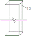
FIG. 2 is a view showing the construction of the edge portion of the lightweight wall panel according to the present invention;
FIG. 3 is a schematic view of the structure of the lower horizontal auxiliary frame in the invention;
FIG. 4 is a schematic view of the structure of the corner connector of the present invention;
FIG. 5 is a schematic view of the structure of the base angle connector of the present invention;
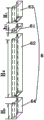
FIG. 6 is a schematic view of a vertical attachment frame according to the present invention;
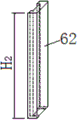
FIG. 7 is a schematic view of the second attachment frame of FIG. 6;
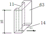
FIG. 8 is a schematic view of the upper extension attachment frame of FIG. 6;
FIG. 9 is a schematic view of the installation of an expansion bolt in one embodiment of the invention;
FIG. 10 is a side view of a corner connector of the present invention;
FIG. 11 is a left side view of FIG. 10;
in the figure: 1-left side wall boards, 2-right side wall boards, 3-upper side wall boards, 4-lower side wall boards, 5-horizontal auxiliary frames, 6-vertical auxiliary frames, 61-first section auxiliary frames, 62-second section auxiliary frames, 63-upper extension auxiliary frames and 64-lower extension auxiliary frames; 7-vertex angle connectors, 71-vertical part, 72-horizontal part, 73-horizontal partition, 74-vertical partition; 8-base angle connecting pieces, 9-C-shaped steel, 10-expansion bolts, 11-grooves, 12-tenons, 13-strip holes, 14-clamping grooves, 15-mounting grooves, 16-mounting holes, 17-springs, 18-sleeves and 19-nuts.
Description of the embodiments
The following description of the embodiments of the present invention will be made clearly and fully with reference to the accompanying drawings, in which it is evident that the embodiments described are only some, but not all embodiments of the invention. All other embodiments, which can be made by those skilled in the art based on the embodiments of the invention without making any inventive effort, are intended to be within the scope of the invention.
Referring to fig. 1, the assembled wallboard heat-bridge-free installation structure with the door and window hole provided by the invention comprises four light wallboards arranged around the door and window hole, wherein heat-insulation auxiliary frames are arranged at the edges of the light wallboards around the door and window hole, connecting components capable of being connected with embedded parts in the light wallboards are respectively arranged at four sides and four corners of the door and window hole, and the connecting components are arranged between the heat-insulation auxiliary frames and the light wallboards. Wherein the embedded part is an embedded bolt; four light wallboards are respectively left wallboard 1, right wallboard 2, go up side wallboard 3 and downside wallboard 4, the heat preservation attaches the frame and attaches frame 5 and both sides perpendicular including upper and lower level and attaches frame 6, coupling assembling includes two apex angle connecting pieces 7, two bottom angle connecting pieces 8 and four sections C shaped steel 9 that set up in door and window hole all around, the C shaped steel of door and window hole left and right sides sets up between corresponding roof beam and floor, the C shaped steel of door and window hole upper and lower both sides corresponds and sets up between apex angle connecting pieces and bottom angle connecting pieces, C shaped steel passes through expansion bolts 10 and links to each other with light wallboard, the horizontal level attaches frame 5 and attaches frame 6's middle part along its length direction all be equipped with C shaped steel 9 outside matched with recess 11, the inside edge of upper side wallboard 3 and downside wallboard 4, the right side edge of left side wallboard 1 and the left side edge of right side wallboard 2 all are equipped with C9 inside groove matched with tenon 12, as shown in fig. 2, 3. The heat-insulating auxiliary frame and the light wallboard can be conveniently installed by adopting the clamping structure, and the outside of the C-shaped steel is buckled by means of the connecting components at four corners, so that firm connection is ensured. Meanwhile, bolts are embedded at the edge of the light wallboard according to the design size, conditions are reserved for mounting the light wallboard and the connecting assembly, the later-stage dry type quick mounting is convenient, and the later-stage damage to the light wallboard is avoided. The beam and the floor slab are respectively and correspondingly arranged at the top and the bottom of the light wallboard, the upper end and the lower end of the C-shaped steel at the left side and the right side of the door and window hole are fixedly connected to the beam and the floor slab through welding or bolts, and the strength and the stability of the integral structure can be improved by means of the C-shaped steel.
In one embodiment of the present invention, as shown in fig. 4, the top corner connector 7 includes a vertical portion 71 and a horizontal portion 72, one ends of the vertical portion 71 and the horizontal portion 72 are vertically connected, the vertical portion 71 is disposed between the vertical auxiliary frame 6 and the left side wall panel 1 or the right side wall panel 2, and embedded parts in the left side wall panel 1 and the right side wall panel 2 are respectively connected with the corresponding vertical portion 71; the horizontal part 72 is arranged between the horizontal auxiliary frame 5 and the upper side wall plate 3, and an embedded part in the upper side wall plate 3 is connected with the horizontal part 72; two bottom corner connecting pieces 8 are respectively arranged at two ends of the lower side wall plate 4, one bottom corner connecting piece 8 can be connected with embedded parts in the left side wall plate 1 and the lower side wall plate 4, and the other bottom corner connecting piece 8 can be connected with embedded parts in the right side wall plate 2 and the lower side wall plate 4.
In the concrete manufacturing process, as shown in fig. 5, the bottom angle connecting piece 8 is an angle steel, and both sides of the angle steel are provided with strip holes 13 matched with the embedded piece; the apex angle connecting piece 7 is made of steel plates, and the other ends of the vertical part 71 and the horizontal part 72 are correspondingly provided with strip holes 13 matched with the embedded parts.
Further optimizing the above technical solution, as shown in fig. 4, the top corner connector 7 further includes a horizontal partition 73 and a vertical partition 74, the horizontal partition 73 is vertically fixed in the middle of the inner side of the vertical portion 71 and is parallel to the horizontal portion 72, and the end of the horizontal auxiliary frame 5 is inserted between the horizontal partition 73 and the horizontal portion 72; the vertical partition 74 is vertically fixed to the middle of the lower surface of the horizontal partition 73 and parallel to the vertical portion 71; as shown in fig. 6, the vertical auxiliary frame 6 is of a split structure, the vertical auxiliary frame 6 is sequentially provided with a first section auxiliary frame 61 and a second section auxiliary frame 62 from top to bottom, the first section auxiliary frame 61 is embedded between the horizontal partition 73 and the horizontal portion 72 and is abutted against the end of the horizontal auxiliary frame 5, and the second section auxiliary frame 62 is arranged between the horizontal partition 73 and the bottom corner connecting piece 8.
In order to facilitate installation and ensure close fit between the adjacent light wallboards, as shown in fig. 1 and 6-8, the vertical auxiliary frame 6 further comprises two upper extension auxiliary frames 63 and two lower extension auxiliary frames 64, wherein the upper extension auxiliary frames 63 are arranged between the left wallboard 1 or the right wallboard 2 and the upper sidewall 3 above the door and window hole, and the lower extension auxiliary frames 6 are arranged between the left wallboard 1 or the right wallboard 2 and the lower sidewall 4 below the door and window hole; the middle grooves of the upper extension auxiliary frame 63 and the lower extension auxiliary frame 64 are respectively matched with C-shaped steel at the edge of the left side wall plate 1 or the right side wall plate 2, and the two ends of the upper side wall plate 3 and the lower side wall plate 4 above and below the door and window hole are planes; the bottom of the upper extension auxiliary frame 63 is provided with a clamping groove 14 matched with the width of the vertical part 71, and two ends of the groove of the horizontal auxiliary frame 5 are respectively provided with a mounting groove 15 matched with the vertical auxiliary frame 6.
As a preferable structure, a plurality of mounting holes 16 for being matched with the expansion bolts 10 are arranged in the horizontal auxiliary frame 5 and the vertical auxiliary frame 6 at intervals; as shown in fig. 9, the mounting hole 16 is a taper hole with a large outside and a small inside, a sleeve 18 for sleeving the spring 17 is arranged in the mounting hole 16, the shapes of the spring 17 and the sleeve 18 are both taper shapes matched with the mounting hole 16, the distance between the top of the sleeve 18 and the orifice of the mounting hole 17 is larger than the height of a nut 19 of the expansion bolt 10, the spring can be compressed in the mounting hole by the nut, and foaming polyurethane is encapsulated after the spring is mounted, so that the functions of sealing and heat insulation are achieved; the inner hole of the sleeve 18 is matched with the rod body of the expansion bolt 10, the outer diameter of a nut of the expansion bolt 10 is larger than the outer diameter of the spring 17, and the outer diameter of the bottom of the sleeve 18 is larger than the diameter of an orifice for installing the expansion bolt on a lightweight wallboard. The structure can realize flexible connection of the expansion bolts and the heat preservation auxiliary frame, and damage to the heat preservation auxiliary frame is avoided.
In the specific manufacturing process, the size design requirements of each part are as follows:
1. the thickness of the C-shaped steel 9 is not less than 10mm, the width of the inner side of the notch is consistent with the tenon of the light wallboard, and the installation error is less than or equal to 5mm. And a long strip hole is formed at the corresponding position of the C-shaped steel in advance according to the position of the embedded part on the light wallboard to serve as a bolt mounting hole, the size of the long strip hole can be determined according to the diameter d of the expansion bolt, and the length of the long strip hole is more than or equal to d+100mm.
2. The vertex angle connecting piece 7 is formed by welding steel plates with the thickness t more than or equal to 10mm, the lengths L of the horizontal part and the vertical part are more than or equal to 300mm, the width W is consistent with the outer dimension width of the C-shaped steel, and h 1 And the positioning of the strip holes is more than or equal to 100mm, and the positioning of the strip holes is determined centrally according to the positions of the expansion bolts. As shown in fig. 10 and 11.
3. The angle steel 8 is made of common angle steel, the thickness t is consistent with the thickness t of the connecting piece of the top angle, the width W is consistent with the width of the outer dimension of the C-shaped steel, and the length M is more than or equal to 150mm. The elongated holes are sized in accordance with the foregoing and are centrally located in the angle.
4. The heat preservation auxiliary frame is made of high-density hard polyurethane, the heat conductivity coefficient of polyurethane heat preservation is less than or equal to 0.02W/(m.K), and the high-density hard polyurethane adopts a special process, so that the heat preservation and heat insulation effect is good, and the compressive strength is high. The width of the heat preservation auxiliary frame groove is kept consistent with the width of the outer side of the C-shaped steel, and the installation error is less than or equal to 5mm.
5. And (3) designing a vertical auxiliary frame: the length of the upper extension auxiliary frame is H 1 The total width of the side wall plate on the window opening is kept consistent, the lower end of the side wall plate is provided with a clamping groove with the thickness t, and a space is reserved for placing the vertex angle connecting piece; the length of the first auxiliary frame is h 1 H in the connecting piece with the vertex angle 1 And keep the same. The length of the second section of the auxiliary frame is H 2 The length is consistent with the height of the window opening, and the length of the lower extension auxiliary frame is H 3 Keeping the same with the total width of the wall plate at the lower side of the window opening.
6. The lengths of the upper side wall plate and the lower side wall plate of the window opening are consistent with the width of the window opening, the horizontal auxiliary frame is not cut any more, and the two sides are provided with the thickness t and the length L-h 1 Is provided.
The invention also provides a mounting construction method of the assembled wallboard with the door and window holes, which comprises the following specific construction steps of:
s1: prefabricating a light wallboard, a heat-insulating auxiliary frame and a connecting assembly according to the reserved positions and the reserved sizes of the inner beam, the column members and the door and window holes of the building main body;
s2: installing the left part of the door and window hole: the installation sequence is left wallboard, left C-shaped steel and upper extension auxiliary frame in sequence; mounting left vertex angle connecting pieces, and arranging a first section auxiliary frame and a second section auxiliary frame in the left vertex angle connecting pieces, wherein the left bottom angle connecting pieces and the left lower extension auxiliary frame are arranged; and installing expansion bolts on the left wallboard, and fixing the left wallboard, the C-shaped steel, the heat preservation auxiliary frame, the top angle connecting piece and the bottom angle connecting piece.
S3: installing the upper part of the door and window hole: the installation sequence is that an upper side wallboard, upper side C-shaped steel and an upper side horizontal auxiliary frame are sequentially arranged, and after the upper side wallboard, the upper side C-shaped steel and the upper side horizontal auxiliary frame are put according to the positions, upper side bolts of left upper side vertex angle connectors are installed;
s4: installing the lower part of the door and window hole: the installation sequence is that a lower side wallboard, lower side C-shaped steel and a lower horizontal auxiliary frame are arranged in sequence, and after the lower side wallboard, the lower left side C-shaped steel bolt is installed;
s5: installing the right part of the door and window hole: the installation sequence is that an upper extending auxiliary frame on the right side, a first auxiliary frame and a second auxiliary frame on the right side, a right top angle connecting piece, a right lower angle steel, a lower extending auxiliary frame on the right side, a right C-shaped steel and a right wallboard;
s6: installing expansion bolts on the right side wallboard, the upper side wallboard and the lower side wallboard;
s7: plugging: after the main body part is installed, filling and plugging gaps at expansion bolts around a door and window hole, vertex angle connectors at four corners and bottom angle connectors by using foaming polyurethane, so that the integrity and compactness of the heat insulation layer are ensured;
s8: and (3) air tightness treatment: after the foaming polyurethane is filled, the PE rod seals the gap, the sealant is smeared on the surface layer, the waterproof steam barrier film is stuck on the indoor side, and the waterproof steam permeable film is stuck on the outdoor side, so that the high-efficiency airtight layer is formed.
After the installation of the process is completed, the installation of doors and windows can be performed. The door and window is directly installed on the heat preservation attached frame, the installation mode of the ultralow energy consumption window is not limited, the door and window can be externally hung and externally embedded, the later replacement and disassembly can be safely and conveniently carried out, and the ultralow energy consumption heat-free bridge requirement can be met.
In the foregoing description, numerous specific details are set forth in order to provide a thorough understanding of the present invention, but the present invention may be practiced in other ways other than those described herein, and persons skilled in the art will readily appreciate that the present invention is not limited to the specific embodiments disclosed above.
Claims (6)
1. Take assembled wallboard of door and window hole to have no hot bridge mounting structure, its characterized in that: the light wall board comprises four light wall boards arranged around a door and window hole, wherein heat-preservation auxiliary frames are arranged at the edges of the light wall boards around the door and window hole, connecting components capable of being connected with embedded parts in the light wall boards are respectively arranged at four sides and four corners of the door and window hole, and the connecting components are arranged between the heat-preservation auxiliary frames and the light wall boards; the four light wallboards are respectively a left wallboard, a right wallboard, an upper side wallboard and a lower wallboard, the heat preservation auxiliary frames comprise an upper horizontal auxiliary frame, a lower horizontal auxiliary frame and two sides vertical auxiliary frames, the connecting component comprises two vertex angle connecting pieces, two bottom angle connecting pieces and four sections of C-shaped steel arranged around a door and window hole, the upper and lower ends of the C-shaped steel on the left side and the right side of the door and window hole are arranged between corresponding beams and floors, the C-shaped steel on the upper and the lower sides of the door and window hole is correspondingly arranged between the vertex angle connecting pieces and the bottom angle connecting pieces, the C-shaped steel is connected with the light wallboards through expansion bolts, grooves matched with the outer sides of the C-shaped steel are respectively arranged in the middle parts of the horizontal auxiliary frames and the vertical auxiliary frames along the length direction of the horizontal auxiliary frames, and tenons matched with the inner side edges of the C-shaped steel are respectively arranged on the inner side edges of the upper wallboard and the lower wallboard, the right side edge of the left wallboard and the left side opening part of the door and window hole corresponding to the C-shaped steel groove part; the vertical corner connecting piece comprises a vertical part and a horizontal part, one ends of the vertical part and the horizontal part are vertically connected, the vertical part is arranged between the vertical auxiliary frame and the left side wallboard or the right side wallboard, and embedded parts in the left side wallboard and the right side wallboard are respectively connected with the corresponding vertical parts; the horizontal part is arranged between the horizontal auxiliary frame and the upper side wall plate, and the embedded part in the upper side wall plate is connected with the horizontal part; two bottom corner connecting pieces are respectively arranged at two ends of the lower side wallboard, one bottom corner connecting piece can be connected with embedded parts in the left side wallboard and the lower side wallboard, and the other bottom corner connecting piece can be connected with embedded parts in the right side wallboard and the lower side wallboard; the vertex angle connecting piece further comprises a horizontal partition plate and a vertical partition plate, wherein the horizontal partition plate is vertically fixed in the middle of the inner side of the vertical part and is parallel to the horizontal part, and the end part of the horizontal auxiliary frame is inserted between the horizontal partition plate and the horizontal part; the vertical partition board is vertically fixed in the middle of the lower surface of the horizontal partition board and is parallel to the vertical part; the vertical auxiliary frame is of a split structure, the vertical auxiliary frame is a first section auxiliary frame and a second section auxiliary frame from top to bottom in sequence, the first section auxiliary frame is embedded between the horizontal partition plate and the horizontal part and is abutted to the end part of the horizontal auxiliary frame, and the second section auxiliary frame is arranged between the horizontal partition plate and the bottom corner connecting piece.
2. The assembled wallboard heat bridge-free mounting structure with door and window openings of claim 1, wherein: the bottom angle connecting piece is angle steel, and strip holes matched with the embedded piece are formed in two sides of the angle steel; the other ends of the vertical part and the horizontal part are correspondingly provided with strip holes matched with the embedded parts.
3. The assembled wallboard heat bridge-free mounting structure with door and window openings of claim 2, wherein: the two sides of the vertical auxiliary frames also comprise two upper extension auxiliary frames and two lower extension auxiliary frames, and an upper extension auxiliary frame and a lower extension auxiliary frame are respectively arranged on the upper part and the lower part of each vertical auxiliary frame; the upper extension auxiliary frame is arranged between the left side wall plate or the right side wall plate above the door and window hole and the upper side wall plate, and the lower extension auxiliary frame is arranged between the left side wall plate or the right side wall plate below the door and window hole and the lower side wall plate; the middle grooves of the upper extension auxiliary frame and the lower extension auxiliary frame are respectively matched with C-shaped steel at the edges of the left side wallboard or the right side wallboard, and the two ends of the upper side wallboard and the lower side wallboard above and below the door and window hole are planes; the bottom of the upper extension auxiliary frame is provided with a clamping groove matched with the width of the vertical part, and two ends of the groove of the horizontal auxiliary frame are respectively provided with a mounting groove matched with the vertical auxiliary frame.
4. The assembled wallboard heat bridge-free mounting structure with door and window openings of claim 3, wherein: the horizontal auxiliary frame and the vertical auxiliary frame are internally provided with a plurality of mounting holes at intervals, the mounting holes are taper holes with large outside and small inside, the mounting holes are internally provided with sleeves sleeved with springs, the shapes of the springs and the sleeves are conical matched with the mounting holes, the distance between the top of the sleeve and the orifice of the mounting hole is greater than the height of a nut of the expansion bolt, and the springs can be compressed in the mounting holes by the nut; the inner hole of the sleeve is matched with the expansion bolt, the outer diameter of a nut of the expansion bolt is larger than the outer diameter of the spring, and the outer diameter of the bottom of the sleeve is larger than the diameter of an orifice for installing the expansion bolt on the light wallboard.
5. The assembled wallboard heat bridge-free mounting structure with door and window openings of claim 1, wherein: the heat preservation auxiliary frame is made of high-density hard polyurethane.
6. The method for installing and constructing the assembled wallboard with the door and window holes, which is used for installing the assembled wallboard without the heat bridge with the door and window holes according to the claim 4, comprises the following steps:
s1: prefabricating a light wallboard, a heat-insulating auxiliary frame and a connecting assembly according to the reserved positions and the reserved sizes of the inner beam, the column members and the door and window holes of the building main body;
s2: installing the left part of the door and window hole: the installation sequence is left wallboard, left C-shaped steel and upper extension auxiliary frame in sequence; mounting left vertex angle connecting pieces, and arranging a first section auxiliary frame and a second section auxiliary frame in the left vertex angle connecting pieces, wherein the left bottom angle connecting pieces and the left lower extension auxiliary frame are arranged; installing expansion bolts on the left wallboard, and fixing the left wallboard, the C-shaped steel, the heat preservation auxiliary frame, the top angle connecting piece and the bottom angle connecting piece;
s3: installing the upper part of the door and window hole: the installation sequence is that an upper side wallboard, upper side C-shaped steel and an upper side horizontal auxiliary frame are sequentially arranged, and after the upper side wallboard, the upper side C-shaped steel and the upper side horizontal auxiliary frame are put according to the positions, upper side bolts of left upper side vertex angle connectors are installed;
s4: installing the lower part of the door and window hole: the installation sequence is that a lower side wallboard, lower side C-shaped steel and a lower horizontal auxiliary frame are arranged in sequence, and after the lower side wallboard, the lower left side C-shaped steel bolt is installed;
s5: installing the right part of the door and window hole: the installation sequence is that an upper extending auxiliary frame on the right side, a first auxiliary frame and a second auxiliary frame on the right side, a right top angle connecting piece, a right lower angle steel, a lower extending auxiliary frame on the right side, a right C-shaped steel and a right wallboard;
s6: installing expansion bolts on the right side wallboard, the upper side wallboard and the lower side wallboard;
s7: plugging: filling and plugging gaps at the top corner connecting pieces and the bottom corner connecting pieces at four corners of the expansion bolts around the door and window holes by using foaming polyurethane;
s8: and (3) air tightness treatment: after the foaming polyurethane is filled, the PE rod seals the gap, the sealant is smeared on the surface layer, the waterproof steam barrier film is stuck on the indoor side, and the waterproof steam permeable film is stuck on the outdoor side, so that the high-efficiency airtight layer is formed.
Priority Applications (1)
| Application Number | Priority Date | Filing Date | Title |
|---|---|---|---|
| CN202111451469.3A CN114215215B (en) | 2021-12-01 | 2021-12-01 | Assembled wallboard heat-bridge-free mounting structure with door and window holes and construction method |
Applications Claiming Priority (1)
| Application Number | Priority Date | Filing Date | Title |
|---|---|---|---|
| CN202111451469.3A CN114215215B (en) | 2021-12-01 | 2021-12-01 | Assembled wallboard heat-bridge-free mounting structure with door and window holes and construction method |
Publications (2)
| Publication Number | Publication Date |
|---|---|
| CN114215215A CN114215215A (en) | 2022-03-22 |
| CN114215215B true CN114215215B (en) | 2023-04-25 |
Family
ID=80699200
Family Applications (1)
| Application Number | Title | Priority Date | Filing Date |
|---|---|---|---|
| CN202111451469.3A Active CN114215215B (en) | 2021-12-01 | 2021-12-01 | Assembled wallboard heat-bridge-free mounting structure with door and window holes and construction method |
Country Status (1)
| Country | Link |
|---|---|
| CN (1) | CN114215215B (en) |
Family Cites Families (5)
| Publication number | Priority date | Publication date | Assignee | Title |
|---|---|---|---|---|
| JP2561022Y2 (en) * | 1992-10-13 | 1998-01-28 | ナショナル住宅産業株式会社 | Corner wall panel |
| CN207278083U (en) * | 2017-08-29 | 2018-04-27 | 中国建筑第八工程局有限公司 | The outer wall installation structure of passive window |
| CN107630627A (en) * | 2017-09-26 | 2018-01-26 | 静美幕墙技术有限公司 | The window auxiliary frame and its construction technology used on a kind of light partition wall |
| CN112854543A (en) * | 2020-12-31 | 2021-05-28 | 北新集团建材股份有限公司 | Door and window structure of horizontal wall body and door and window construction method |
| CN112780151A (en) * | 2021-01-21 | 2021-05-11 | 北京市建筑工程研究院有限责任公司 | External hanging type passive window mounting structure for existing building transformation and construction method thereof |
-
2021
- 2021-12-01 CN CN202111451469.3A patent/CN114215215B/en active Active
Also Published As
| Publication number | Publication date |
|---|---|
| CN114215215A (en) | 2022-03-22 |
Similar Documents
| Publication | Publication Date | Title |
|---|---|---|
| WO2008113207A1 (en) | An exterior wall panel and an assembly method thereof | |
| CN113914478B (en) | Modular assembly type building | |
| CN111927248A (en) | Integrally prefabricated external hanging bay window, connecting node and manufacturing method | |
| CN111927249B (en) | Integral prefabricated embedded bay window, connecting node and manufacturing method | |
| CN114215215B (en) | Assembled wallboard heat-bridge-free mounting structure with door and window holes and construction method | |
| CN106988452A (en) | A kind of and supporting industrialization EPS modular wall panel systems of assembled steel framework | |
| CN209384432U (en) | A kind of prefabricated gable and its connecting structure that can be recycled | |
| CN115977258A (en) | ALC wallboard and girder steel and concrete floor joint construction | |
| CN108412089B (en) | Parallel hanging piece, combined wallboard, wall structure and construction method | |
| CN216041886U (en) | Assembled heat preservation wall structure | |
| CN109322411B (en) | Construction method for connecting multi-layer light steel structure building floor slab and wall surface node | |
| CN111926994A (en) | External hanging type prefabricated external window-containing auxiliary frame wallboard module, external wall panel and house building | |
| CN210858409U (en) | Unit type building external window and unit type building external window system | |
| CN203742040U (en) | Novel combined curtain wall system | |
| CN109208850B (en) | Composite wallboard mounting method and assembly component thereof | |
| CN108978857B (en) | Heat preservation and decoration integrated roof board for assembled house | |
| CN111706004A (en) | Frame forming section, assembly type low-rise building and assembly and disassembly method | |
| US20140202100A1 (en) | Insulated wall module | |
| CN212836243U (en) | Outer hanging prefabricated outer window containing auxiliary frame wallboard module, external wall panel and housing construction | |
| CN115387479B (en) | Method for installing multi-layer MIC modular building | |
| CN216432080U (en) | Frameless structure for dehumidifier cabinet | |
| CN213774984U (en) | Prefabricated attached frame suitable for assembly type building and node thereof | |
| CN214835705U (en) | External hanging type passive window mounting structure for existing building transformation | |
| CN213509214U (en) | Assembled low-rise building | |
| CN214941333U (en) | Wall corner connecting node of externally-hung wallboard and assembled building outer wall |
Legal Events
| Date | Code | Title | Description |
|---|---|---|---|
| PB01 | Publication | ||
| PB01 | Publication | ||
| SE01 | Entry into force of request for substantive examination | ||
| SE01 | Entry into force of request for substantive examination | ||
| GR01 | Patent grant | ||
| GR01 | Patent grant |