CN114108577B - But remote regulation's automatic formula farmland sluice - Google Patents
But remote regulation's automatic formula farmland sluice Download PDFInfo
- Publication number
- CN114108577B CN114108577B CN202111548803.7A CN202111548803A CN114108577B CN 114108577 B CN114108577 B CN 114108577B CN 202111548803 A CN202111548803 A CN 202111548803A CN 114108577 B CN114108577 B CN 114108577B
- Authority
- CN
- China
- Prior art keywords
- gate
- rod
- sluice
- wall
- plate
- Prior art date
- Legal status (The legal status is an assumption and is not a legal conclusion. Google has not performed a legal analysis and makes no representation as to the accuracy of the status listed.)
- Active
Links
Images


Classifications
-
- E—FIXED CONSTRUCTIONS
- E02—HYDRAULIC ENGINEERING; FOUNDATIONS; SOIL SHIFTING
- E02B—HYDRAULIC ENGINEERING
- E02B13/00—Irrigation ditches, i.e. gravity flow, open channel water distribution systems
- E02B13/02—Closures for irrigation conduits
-
- E—FIXED CONSTRUCTIONS
- E02—HYDRAULIC ENGINEERING; FOUNDATIONS; SOIL SHIFTING
- E02B—HYDRAULIC ENGINEERING
- E02B7/00—Barrages or weirs; Layout, construction, methods of, or devices for, making same
- E02B7/20—Movable barrages; Lock or dry-dock gates
- E02B7/26—Vertical-lift gates
-
- E—FIXED CONSTRUCTIONS
- E02—HYDRAULIC ENGINEERING; FOUNDATIONS; SOIL SHIFTING
- E02B—HYDRAULIC ENGINEERING
- E02B7/00—Barrages or weirs; Layout, construction, methods of, or devices for, making same
- E02B7/20—Movable barrages; Lock or dry-dock gates
- E02B7/26—Vertical-lift gates
- E02B7/36—Elevating mechanisms for vertical-lift gates
Landscapes
- Engineering & Computer Science (AREA)
- General Engineering & Computer Science (AREA)
- Structural Engineering (AREA)
- Mechanical Engineering (AREA)
- Civil Engineering (AREA)
- Barrages (AREA)
Abstract
The invention discloses a remotely adjustable automatic farmland sluice in the technical field of a distance adjustable automatic farmland sluice, which comprises a U-shaped frame, wherein the lower end of the frame is fixedly provided with a bottom plate, the upper end surface of the bottom plate is provided with a plurality of guide grooves, the inner side wall of the frame is vertically provided with a hollow sluice rod in a sliding manner, the outer side wall of the sluice rod is rotatably provided with two sluice plates for water shutoff, the end head of each sluice plate is provided with a cleaning rod, the outer end of the cleaning rod is coaxially and fixedly provided with a plurality of guide wheels rolling in the guide grooves, the outer wall of the cleaning rod is rotatably provided with a road-opening plate through a rotating ring rotatably arranged at the outer end, and the road-opening plate is fixedly arranged on the side wall of a switching ring; the invention effectively solves the problem that the existing sluice gate usually adopts the vertical sliding water baffle to open and close the gate, and when weeds and stones exist at the lower end of the sluice gate, the gate is affected by the weeds and the stones, and is difficult to vertically close, so that water leakage is caused.
Description
Technical Field
The invention relates to the technical field of a program-regulated automatic farmland sluice, in particular to a remotely-regulated automatic farmland sluice.
Background
Agricultural development is an important foundation of the country, and the construction of hydraulic engineering can directly influence the agricultural development, so that people must master related technologies in the construction process of the hydraulic engineering, such as the design and construction technology of a sluice; the water level intercepting the upstream is generally higher, which causes a large water level difference between the upstream and the downstream of the sluice, and the phenomenon of excessive horizontal pressure can occur, so that the sluice moves in the downstream direction. To stabilize itself, the floodgate must have a certain weight. In addition, after the sluice is built, if water is not retained or no water is available in normal use, a large vertical load is generated, so that the actual pressure of the foundation greatly exceeds the bearing capacity of the foundation, the foundation is deformed or the soil of the sluice foundation is extruded, and the sluice and the foundation are easy to slide.
The farmland contains a lot of weeds and stones, and during the drainage period of the sluice, water flow can drive the weeds and stones to move to the sluice gate, the existing sluice is usually opened and closed by adopting a vertical sliding water baffle plate due to cost reasons, and when the weeds and stones exist at the lower end of the sluice gate, the sluice gate is influenced by the weeds and the stones and is difficult to be vertically closed, so that the problem of water leakage is caused; secondly because be long-range gate to can not carry out effectual manual cleaning, directly close and lead to the gate to appear the problem of damaging easily.
Based on the above, the invention designs an automatic farmland sluice capable of being remotely adjusted so as to solve the problems.
Disclosure of Invention
The invention aims to provide an automatic farmland sluice gate capable of being remotely adjusted, and aims to solve the problem that the farmland provided by the background art contains a lot of weeds and stones, and during the drainage period of the sluice gate, water flow can drive the weeds and the stones to move to a sluice gate opening; secondly because be long-range gate to can not carry out effectual manual cleaning, directly close and lead to the problem that the gate appears damaging easily.
In order to achieve the purpose, the invention provides the following technical scheme: the utility model provides a but remotely regulated's automatic formula farmland sluice, includes the frame of U type, the fixed bottom plate that is provided with of frame lower extreme, a plurality of guiding grooves have been seted up to the bottom plate up end, the vertical slip of frame inside wall is provided with hollow brake lever, the brake lever lateral wall rotates and is provided with two flashboards that are used for water shutoff, every the flashboard end is provided with the clearance pole, the coaxial fixed a plurality of guide wheels that roll in the guiding groove that are provided with in clearance pole outer end, clearance pole outer wall rotates through the swivel becket that rotates to set up in the outer end and is provided with the division board, the division board is fixed to be set up at the switching annulus lateral wall, the inclined plane that is used for promoting the barrier to the guiding groove of division board lateral wall is seted up to division board lateral wall, the brake lever end is provided with the drive arrangement who is used for driving the brake lever descends.
As a further scheme of the invention, the driving device comprises a motor capable of being operated remotely, the motor is fixedly arranged at the upper end of the rack, the end of the motor is meshed with a power gear through an end head and a gear fixedly arranged on the motor, a driving sleeve rotatably arranged at the upper end of the rack is fixedly arranged at the center of the power gear, a lifting rod is axially and slidably arranged in the driving sleeve, the lower end of the lifting rod penetrates through the brake rod and is rotatably connected with the brake rod, and a displacement device for driving the brake rod to move up and down is arranged at the center of the brake rod; the displacement device comprises a displacement shaft which is rotatably arranged on the inner wall of the brake lever, the outer wall of the center of the displacement shaft is in transmission connection with the lifting lever through a reversing bevel gear set in transmission connection with the displacement shaft, a cavity for avoiding the reversing bevel gear set is formed in the inner wall of the brake lever, two ends of the displacement shaft are inserted into the side wall of the rack, the side wall of the rack is provided with vertical long round holes which are used for avoiding and limiting the displacement shaft to slide left and right, and two ends of the displacement shaft are respectively provided with a stepping device for driving the brake lever to descend; the stepping device comprises a stepping gear arranged at the end of the displacement shaft, a vertical long circular cavity is formed in the side wall of the rack, and stepping teeth meshed with the stepping gear are formed in the side wall of the long circular cavity.
As a further scheme of the invention, a plurality of planetary gears which are annularly arrayed around the axis of the displacement shaft are meshed between the inner walls of the two stepping gears and the displacement shaft, a rotating ring plate which is coaxial with the displacement shaft is rotatably arranged on each of the side walls of the planetary gears on the same side, a rotating sleeve which is rotatably arranged on the outer wall of the displacement shaft is coaxially and fixedly arranged on the side walls of the two rotating ring plates, and a cleaning device which is used for driving the guide wheel to rotate to clean an obstacle when the descending of the displacement shaft is blocked is arranged on the outer wall of the rotating sleeve; cleaning device includes the differential rod, the rotation of cleaning rod sets up at the flashboard end, it is connected with a plurality ofly through multiunit clearance bevel gear group transmission respectively and guides the corresponding differential rod of wheel, a plurality of to rotate the differential rod and set up respectively at two flashboard lower extreme lateral walls, the brake lever lateral wall is offered and is used for dodging the differential rod and keeps away the groove along with the flashboard rotates the long circle, the differential rod other end is provided with the locking means when the guide wheel does not rotate the clearance guide groove in the barrier.
As a further aspect of the present invention, the locking device includes worm teeth formed on an end of each differential rod, and the cleaning rod is formed with worm teeth at a position corresponding to the differential rod for meshing with the worm teeth.
As a further scheme of the invention, a side guard plate for shielding the lower end of the flashboard when the flashboard descends in an inclined manner to prevent sundries from entering the lower end of the flashboard to block the flashboard is fixedly arranged between the side wall of the rack and the bottom plate.
Compared with the prior art, the invention has the beneficial effects that: 1. the driving device drives the brake rod to descend so as to drive the upper end of the brake plate to descend. Meanwhile, the lower end of the gate plate is acted by the bottom plate, so that the upper end of the gate plate rotates around the descending side of the gate rod, the splayed angle formed by the two gate plates is slowly increased, the two gate plates are slowly put down, the side surfaces of the gate plates can be positioned at the bottom of the gate, and meanwhile, sundries at the upper end of the bottom plate can be quickly cleaned away through the lower end of the gate plate and the rotating road-opening plate; thereby avoiding the problem of the blocking of the flashboard; when the gate needs to be closed, the upper ends of the two gate plates are lifted, so that the splayed angle formed by the two gate plates is slowly reduced, impurities at the gate opening of the gate are stirred to the two sides of the two gate plates, and the problem that the gate is blocked when being closed is avoided.
2. The invention adopts the rotation of the displacement shaft in the center of the gate rod, so that the stepping gears at the two ends are meshed with the stepping teeth, the gate rod is enabled to move up and down actively, the lifting rod slides axially in the driving sleeve, the driving sleeve and the lifting rod only bear the rotation torque, and the problem that the upper end of the rack is deformed due to the large span of the rack because the upper end of the rack is directly stressed by the force of the gate rod and the gate plate which are often driven by a lead screw is avoided.
3. According to the invention, the planetary gear automatically revolves when the opening of the gate plate is blocked, so that the guide wheel is indirectly driven to rotate, the barrier in the guide groove is cleaned and thrown out, the barrier is actively cleared, the opening action of the gate plate and the action of clearing the barrier are actively switched, and the problem that the opening of the gate plate is influenced because too many barriers are accumulated on the bottom surface in the closing time of the gate plate on the existing bottom plate is effectively solved.
Drawings
In order to more clearly illustrate the technical solutions of the embodiments of the present invention, the drawings used in the description of the embodiments will be briefly introduced below, and it is obvious that the drawings in the following description are only some embodiments of the present invention, and it is obvious for those skilled in the art that other drawings can be obtained according to the drawings without creative efforts.
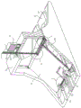
FIG. 1 is a schematic diagram of the overall structure of the present invention; FIG. 2 is a schematic view of the right side in partial cross-section of the present invention;
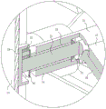
FIG. 3 is an enlarged schematic view of the structure at A in FIG. 2 according to the present invention;
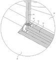
FIG. 4 is an enlarged view of the structure at B in FIG. 2 according to the present invention;
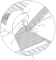
FIG. 5 is an enlarged view of the structure of FIG. 2 at C according to the present invention;
FIG. 6 is a left side elevational view partially in section and is shown in cross-section;
FIG. 7 is an enlarged view of the structure shown at D in FIG. 6 according to the present invention;
FIG. 8 is an enlarged view of E of FIG. 6 according to the present invention;
FIG. 9 is an enlarged view of the structure of FIG. 6 at F according to the present invention;
FIG. 10 is an enlarged view of the structure at G in FIG. 6 according to the present invention.
In the drawings, the components represented by the respective reference numerals are listed below: the side guard plate comprises a frame 11, a bottom plate 12, a guide groove 13, a brake rod 14, a brake plate 15, a cleaning rod 16, a guide wheel 17, a rotating ring 18, an opening plate 19, an inclined surface 20, a power gear 22, a driving sleeve 23, a lifting rod 24, a displacement shaft 25, a reversing bevel gear set 26, a stepping gear 28, an elongated cavity 29, stepping teeth 30, planetary gears 32, a rotating ring plate 33, a rotating sleeve 34, a cleaning bevel gear set 35, a differential rod 36, worm teeth 38, worm teeth 39 and a side guard plate 40.
Description of the preferred embodiment
The technical solutions in the embodiments of the present invention will be clearly and completely described below with reference to the drawings in the embodiments of the present invention, and it is obvious that the described embodiments are only a part of the embodiments of the present invention, and not all of the embodiments. All other embodiments, which can be derived by a person skilled in the art from the embodiments given herein without making any creative effort, shall fall within the protection scope of the present invention.
Referring to fig. 1-10, the present invention provides a technical solution: an automatic farmland sluice capable of being remotely adjusted comprises a U-shaped rack 11, wherein a bottom plate 12 is fixedly arranged at the lower end of the rack 11, a plurality of guide grooves 13 are formed in the upper end face of the bottom plate 12, a hollow sluice rod 14 is vertically and slidably arranged on the inner side wall of the rack 11, two sluice plates 15 for blocking water are rotatably arranged on the outer side wall of the sluice rod 14, a cleaning rod 16 is arranged at the end of each sluice plate 15, a plurality of guide wheels 17 in the guide grooves 13 are coaxially and fixedly arranged at the outer end of the cleaning rod 16, an opening plate 19 is rotatably arranged on the outer wall of the cleaning rod 16 through a rotating ring 18 rotatably arranged at the outer end, the opening plate 19 is fixedly arranged on the side wall of the rotating ring 18, an inclined plane 20 for pushing an obstacle into the guide grooves 13 is formed in the side wall of the opening plate 19, and a driving device for driving the sluice rod 14 to descend is arranged at the end of the sluice rod 14;
when the device is used, the device is assembled and the equipment is electrified (as shown in figure 1, the device adopts a symmetrical design, and can be directly installed on a water channel when being installed without being installed front and back, so that the installation time of the equipment is shortened, and secondly, the device is outdoor equipment, and a power supply preferably adopts solar energy or wind energy);
when the device is used, the driving device is started, the driving device works, the gate rod 14 is driven to descend, the gate rod 14 descends to drive the lower end of the gate plate 15 to descend, the lower end of the gate plate 15 is limited at the upper end of the bottom plate 12 by the guide wheel 17 and the cleaning rod 16, so that the gate plate 15 can only obliquely slide at the upper end of the bottom plate 12 (as shown in fig. 1, the two gate plates 15 are also in an oblique state in an initial closing state and are not perpendicular to the bottom plate 12, so that the problem of dead angles is avoided); the problem that the driving mechanism bears excessive load pressure and is damaged due to the fact that water flow is forcibly blocked when a conventional gate which vertically moves up and down is closed is solved; when the gate plate 15 rotates and descends, the cleaning rod 16 at the lower end drives the rotating ring 18 to slide towards the outer end of the bottom plate 12, the rotating ring 18 moves outwards to drive the opening plate 19 to move outwards, and the sharp end in front of the opening plate 19 pushes the sundries on the upper end of the bottom plate 12, which are opened by the gate plate 15, outwards (as shown in fig. 2 and 3, the opening plate 19 and the gate plate 15 rotate, so that the bottom surface of the opening plate 19 and the lower edge of the gate plate 15 can always cling to the bottom plate 12 to push away the sundries on the upper end of the bottom plate 12 and keep sealed), meanwhile, the sundries can also be pushed into the guide groove 13, and the sundries are pushed to move when waiting for the guide wheel 17 to pass through, or the sundries can be directly pushed up (the guide wheel 17 can also guide the gate plate 15 to linearly move along the guide groove 13 through the cleaning rod 16, so as to avoid the water pressure on the gate plate 15, and the direction swing when the guide wheel 15 moves, so that the sundries are blocked in the inclined plane 11), and the inclined plane 20 on the opening plate 19 can flow downstream along with the water flow, and then the sundries can also be pushed up on the bottom plate 12;
the invention drives the brake bar 14 to descend through the driving device so as to drive the upper end of the brake plate 15 to descend. Meanwhile, the lower end of the gate plate 15 is acted by the bottom plate 12, so that the upper end of the gate plate 15 rotates around the gate rod 14 while descending, the splayed angle formed by the two gate plates 15 is slowly increased, the two gate plates 15 are slowly put down, the side surfaces of the gate plate 15 can be positioned at the bottom of the gate, and meanwhile, sundries at the upper end of the bottom plate 12 can be quickly cleaned away through the lower end of the gate plate 15 and the rotating road-opening plate 19; thereby avoiding the problem of the flashboard 15 being stuck; when the gate needs to be closed, the upper ends of the two gate plates 15 are lifted, so that the splayed angle formed by the two gate plates 15 is slowly reduced, impurities at the gate opening of the gate are stirred to the two sides of the two gate plates 15, and the problem that the gate is blocked when being closed is avoided.
As a further scheme of the invention, the driving device comprises a motor 10 capable of being operated remotely, the motor 10 is fixedly arranged at the upper end of the frame 11, the end of the motor 10 is meshed with a power gear 22 through an end head and a gear fixedly arranged on the end of the motor 10, a driving sleeve 23 rotatably arranged at the upper end of the frame 11 is fixedly arranged at the center of the power gear 22, a lifting rod 24 is axially and slidably arranged in the driving sleeve 23, the lower end of the lifting rod 24 penetrates through the brake rod 14 and is rotatably connected with the brake rod 14, and a displacement device for driving the brake rod 14 to move up and down is arranged at the center of the brake rod 14; the displacement device comprises a displacement shaft 25 which is rotatably arranged on the inner wall of the brake rod 14, the outer wall of the center of the displacement shaft 25 is in transmission connection with a lifting rod 24 through a reversing bevel gear set 26 in transmission connection with the displacement shaft, the inner wall of the brake rod 14 is provided with a cavity for avoiding the reversing bevel gear set 26, two ends of the displacement shaft 25 are inserted into the side wall of the rack 11, the side wall of the rack 11 is provided with vertical long round holes which are used for avoiding and limiting the displacement shaft 25 to slide left and right, and two ends of the displacement shaft 25 are both provided with stepping devices for driving the brake rod 14 to descend; the stepping device comprises a stepping gear 28 arranged at the end of the displacement shaft 25, a vertical long circular cavity 29 is formed in the side wall of the rack 11, and stepping teeth 30 meshed with the stepping gear 28 are formed in the side wall of the long circular cavity 29;
when the invention is used, the motor 10 rotates to drive the power gear 22 to rotate, the power gear 22 rotates to drive the driving sleeve 23 which is arranged on the frame 11 to rotate, the driving sleeve 23 rotates to drive the lifting rod 24 to rotate, the lifting rod 24 rotates to drive the displacement shaft 25 which is arranged at the center of the brake rod 14 to rotate through the reversing bevel gear group 26 at the end (as shown in figure 8), the displacement shaft 25 rotates to drive the stepping gears 28 at two ends to rotate, the stepping gears 28 rotate to be meshed with the stepping teeth 30 on the inner wall of the long round cavity 29, so as to drive the stepping gears 28 to move up and down, simultaneously, the stepping gears 28 move up and down to drive the displacement shaft 25 to move up and down, the lifting rod 24 moves up and down in the driving sleeve 23, so as to compensate the up and down displacement of the driving brake rod 14 (as shown in figure 6, wherein the lifting rod 24 is arranged at the lower end, when the lifting rod 24 slides upwards into the driving sleeve 23, impurities attached to the outer wall of the lifting rod 24 are cleaned, so that the lifting rod 24 is prevented from being corroded and rusted, the service life of the lifting rod 24 is prolonged, the displacement shaft 25 moves upwards and downwards to drive the brake rod 14 to move upwards and downwards, and the brake rod 14 automatically moves upwards and downwards under the action of the stepping gear 28 and the stepping teeth 30 in the long circular cavity 29 (as shown in fig. 7, the long circular cavity 29 avoids the stepping gear 28 at the end of the displacement shaft 25 while being meshed with the stepping teeth 30, wherein a vertical long circular hole formed in the rack 11 moves upwards and downwards to avoid the displacement shaft 25, and the transverse movement of the displacement shaft 25 is limited, so that the problems that the stepping gear 28 is separated from the stepping teeth 30 and power is interrupted are solved);
according to the invention, the displacement shaft 25 in the center of the gate rod 14 is adopted to rotate, so that the stepping gears 28 at two ends are meshed with the stepping teeth 30, the gate rod 14 is enabled to move up and down actively, the lifting rod 24 slides axially in the driving sleeve 23, the driving sleeve 23 and the lifting rod 24 only bear the rotation moment, and the problem that the upper end of the rack 11 is deformed due to the fact that the upper end of the rack 11 directly bears the force of the gate rod 14 and the gate plate 15 because the rack 11 has a large span due to the fact that the gate is driven by a conventional screw rod is avoided.
As a further scheme of the invention, a plurality of planetary gears 32 which are annularly arrayed around the axis of the displacement shaft 25 are meshed between the inner walls of the two stepping gears 28 and the displacement shaft 25, the side wall of each planetary gear 32 on the same side is rotatably provided with a rotating ring plate 33 which is coaxial with the displacement shaft 25, the side walls of the two rotating ring plates 33 are coaxially and fixedly provided with rotating sleeves 34 which are rotatably arranged on the outer wall of the displacement shaft 25, and the outer wall of each rotating sleeve 34 is provided with a cleaning device which is used for driving the guide wheels 17 to rotate to clean obstacles when the displacement shaft 25 is hindered from descending; the cleaning device comprises differential rods 36, the cleaning rods 16 are rotatably arranged at the ends of the gate plates 15, the outer wall of the rotating sleeve 34 is respectively connected with a plurality of differential rods 36 corresponding to the guide wheels 17 in a transmission manner through a plurality of cleaning bevel gear sets 35, the differential rods 36 are respectively rotatably arranged on the side walls of the lower ends of the two gate plates 15, the side walls of the gate rods 14 are provided with long avoidance grooves for avoiding the differential rods 36 rotating with the gate plates 15, and the other ends of the differential rods 36 are provided with locking devices when the guide wheels 17 do not rotate to clean obstacles in the guide grooves 13; the locking device comprises worm teeth 38 formed at the end of each differential lever 36, and worm teeth 39 formed at the corresponding positions of the cleaning lever 16 and the differential lever 36 for meshing with the worm teeth 38.
When the invention is used, when the displacement shaft 25 rotates, the planet gear 32 is driven to rotate automatically, the planet gear 32 rotates automatically, so that the outer stepping gear 28 is driven to rotate on the stepping tooth 30, the brake rod 14 moves up and down, and the brake plate 15 is opened and closed; when the gate plate 15 is opened, as the gate plate 19 cleans more and more obstacles into the guide groove 13, the guide wheel 17 is blocked from moving and can not be further pushed, when sundries are fully accumulated in the guide groove 13 at the front end of the guide wheel 17 at the edge of the lower end of the gate plate 15, the guide wheel 17 can not be pushed to move forwards in a translation way, the step gear 28 is clamped on the step tooth 30 and can not rotate, as the continuous power input of the motor 10, the planetary gear 32 revolves and rotates, so that the rotating ring plate 33 rotates on the outer side of the displacement shaft 25, the rotating ring plate 33 drives the rotating sleeve 34 to rotate on the outer wall of the displacement shaft 25 (as shown in fig. 5, the rotating sleeve 34 also rotates on the inner wall of the gate rod 14), the rotating sleeve 34 rotates to drive the differential rod 36 to rotate through the cleaning bevel gear set 35, the differential lever 36 rotates to drive the worm teeth 39 outside the cleaning rod 16 through the end worm teeth 38 (wherein, as shown in fig. 9 and 10, since the guide wheel 17 normally slides forward in the guide groove 13, the rotation direction is opposite to the device active driving direction, although the planetary gear 32 is driven to actively revolve when descending along with the gate lever 14, the guide wheel 17 has a reverse rotation tendency and the locking action of the worm teeth 39 and the worm teeth 38, so that the guide wheel 17 can only be locked when descending the gate 15, pushing an obstacle forward, so that the upper end worm teeth 39 and the worm teeth 38 cannot be driven smoothly, thereby keeping the planetary gear 32 in rotation without revolving, and improving the closing efficiency of the gate 15), so that the cleaning rod 16 rotates to drive the guide wheel 17 to rotate, so that the contact point between the guide wheel 17 and the bottom end of the guide groove 13 rotates outward of the guide groove 13, therefore, sundries in the guide groove 13 are thrown upwards and outwards, the sundries in the guide groove 13 are directly thrown to the outer side or directly flow to the downstream along with water flow, and along with the continuous sliding of the lower end of the gate plate 15, the planet gear 32 rotates again without revolution, so that the guide wheel 17 continues to translate to push obstacles in the guide groove 13;
according to the invention, the planet gear 32 automatically revolves when the opening of the gate plate 15 is blocked, so that the guide wheel 17 is indirectly driven to rotate, the barrier in the guide groove 13 is cleaned and thrown out, the barrier is actively cleared, the opening action of the gate plate 15 and the barrier clearing action are actively switched, and the problem that the opening of the gate plate 15 is influenced because too many barriers are accumulated on the bottom surface in the closing time of the gate plate on the existing bottom plate 12 is effectively solved.
As a further proposal of the invention, a side protection plate 40 for shielding the lower end of the flashboard 15 when the flashboard 15 descends obliquely to prevent sundries from entering the lower end of the flashboard 15 to block the flashboard 15 is fixedly arranged between the side wall of the frame 11 and the bottom plate 12.
Claims (5)
1. The utility model provides a but remote regulation's automatic formula farmland sluice, its characterized in that: the water plugging device comprises a U-shaped rack (11), wherein a bottom plate (12) is fixedly arranged at the lower end of the rack (11), a plurality of guide grooves (13) are formed in the upper end face of the bottom plate (12), a hollow gate rod (14) is vertically and slidably arranged on the inner side wall of the rack (11), two gate plates (15) used for blocking water are rotatably arranged on the outer side wall of the gate rod (14), a cleaning rod (16) is arranged at the end of each gate plate (15), a plurality of guide wheels (17) in the guide grooves (13) are coaxially and fixedly arranged at the outer end of each cleaning rod (16), an opening plate (19) is rotatably arranged on the outer wall of each cleaning rod (16) through a rotating ring (18) which is rotatably arranged at the outer end of each opening plate (19), the opening plate (19) is fixedly arranged on the side wall of the rotating ring (18), an inclined plane (20) which is obliquely arranged for pushing an obstacle into the guide grooves (13) is formed in the side wall of each opening plate (19), and a driving device used for driving the gate rod (14) to descend is arranged at the end of each gate rod (14);
a plurality of planetary gears (32) which are annularly arrayed around the axis of the displacement shaft (25) are meshed between the inner walls of the two stepping gears (28) and the displacement shaft (25), the side wall of each planetary gear (32) on the same side is rotatably provided with a rotating ring plate (33) which is coaxial with the displacement shaft (25), the side walls of the two rotating ring plates (33) are coaxially and fixedly provided with rotating sleeves (34) which are rotatably arranged on the outer wall of the displacement shaft (25), and the outer wall of each rotating sleeve (34) is provided with a cleaning device which is used for driving the guide wheels (17) to rotate to clean obstacles when the displacement shaft (25) is hindered from descending;
the cleaning device comprises differential rods (36), the cleaning rods (16) are rotatably arranged at the ends of the gate plates (15), the outer wall of the rotating sleeve (34) is respectively in transmission connection with a plurality of differential rods (36) corresponding to the guide wheels (17) through a plurality of cleaning bevel gear sets (35), the differential rods (36) are respectively rotatably arranged on the side walls of the lower ends of the two gate plates (15), the side wall of the gate rod (14) is provided with a long avoidance groove for avoiding the differential rods (36) along with the rotation of the gate plates (15), and the other end of the differential rod (36) is provided with a locking device when the guide wheels (17) do not rotate to clean obstacles in the guide grooves (13);
the locking device comprises worm teeth (38) arranged at the end of each differential rod (36), and worm gear teeth (39) used for being meshed with the worm teeth (38) are arranged at the positions, corresponding to the differential rods (36), of the cleaning rod (16).
2. The remotely adjustable automatic farmland sluice as claimed in claim 1, wherein: but drive arrangement is including remote operation's motor (10), motor (10) are fixed to be set up in frame (11) upper end, motor (10) end has power gear (22) through the end rather than the fixed gear engagement who sets up, power gear (22) central authorities are fixed to be provided with and rotate drive cover (23) of setting in frame (11) upper end, the inside axial slip of drive cover (23) is provided with lifter (24), lifter (24) lower extreme passes brake lever (14) and rotates with brake lever (14) to be connected, brake lever (14) central authorities are provided with the displacement device that is used for driving brake lever (14) and reciprocates.
3. The remotely adjustable, automated agricultural water gate of claim 2, wherein: displacement device is including rotating displacement axle (25) that sets up at brake lever (14) inner wall, displacement axle (25) central authorities outer wall is connected to lifter (24) through the switching-over bevel gear group (26) transmission rather than the transmission is connected, brake lever (14) inner wall is provided with the cavity of dodging switching-over bevel gear group (26), frame (11) lateral wall is inserted at displacement axle (25) both ends, and frame (11) lateral wall is seted up vertical being used for dodging and restriction displacement axle (25) horizontal slip's vertical slotted hole, displacement axle (25) both ends all are provided with the stepping device who is used for driving brake lever (14) decline.
4. The remotely adjustable automatic farmland sluice as claimed in claim 3, wherein: the stepping device comprises a stepping gear (28) arranged at the end of a displacement shaft (25), a vertical long circular cavity (29) is formed in the side wall of the rack (11), and stepping teeth (30) meshed with the stepping gear (28) are formed in the side wall of the long circular cavity (29).
5. The remotely adjustable, automated agricultural water gate of claim 1, wherein: and a side protection plate (40) used for shielding the lower end of the flashboard (15) when the flashboard (15) obliquely descends and preventing sundries from entering the lower end of the flashboard (15) to block the flashboard (15) is fixedly arranged between the side wall of the rack (11) and the bottom plate (12).
Priority Applications (1)
| Application Number | Priority Date | Filing Date | Title |
|---|---|---|---|
| CN202111548803.7A CN114108577B (en) | 2021-12-17 | 2021-12-17 | But remote regulation's automatic formula farmland sluice |
Applications Claiming Priority (1)
| Application Number | Priority Date | Filing Date | Title |
|---|---|---|---|
| CN202111548803.7A CN114108577B (en) | 2021-12-17 | 2021-12-17 | But remote regulation's automatic formula farmland sluice |
Publications (2)
| Publication Number | Publication Date |
|---|---|
| CN114108577A CN114108577A (en) | 2022-03-01 |
| CN114108577B true CN114108577B (en) | 2023-03-28 |
Family
ID=80365786
Family Applications (1)
| Application Number | Title | Priority Date | Filing Date |
|---|---|---|---|
| CN202111548803.7A Active CN114108577B (en) | 2021-12-17 | 2021-12-17 | But remote regulation's automatic formula farmland sluice |
Country Status (1)
| Country | Link |
|---|---|
| CN (1) | CN114108577B (en) |
Family Cites Families (6)
| Publication number | Priority date | Publication date | Assignee | Title |
|---|---|---|---|---|
| CA2096269C (en) * | 1993-05-14 | 1997-09-30 | Peter Langemann | Irrigation control structure |
| CN106906799B (en) * | 2017-03-27 | 2019-01-22 | 陈美� | Water conservancy reservoir lift sluice and its control method |
| CN212742441U (en) * | 2020-06-03 | 2021-03-19 | 李海波 | Hydraulic engineering sluice |
| CN213349823U (en) * | 2020-07-15 | 2021-06-04 | 石天禹 | Hydraulic engineering sluice cleaning device |
| CN212772237U (en) * | 2020-08-07 | 2021-03-23 | 张甲栋 | Over-and-under type water sluicegate for hydraulic engineering |
| CN214783714U (en) * | 2021-03-18 | 2021-11-19 | 四川省紫坪铺开发有限责任公司 | Water conservancy water and electricity gate hoisting device |
-
2021
- 2021-12-17 CN CN202111548803.7A patent/CN114108577B/en active Active
Also Published As
| Publication number | Publication date |
|---|---|
| CN114108577A (en) | 2022-03-01 |
Similar Documents
| Publication | Publication Date | Title |
|---|---|---|
| CN213682026U (en) | Sluice rubbish intercepting device for hydraulic engineering | |
| CN110833718B (en) | Front pool filtering device of large irrigation drainage pump station | |
| CN114108577B (en) | But remote regulation's automatic formula farmland sluice | |
| CN110374277B (en) | Snow cleaning device for preventing large-scale color steel ceiling of factory building from collapsing due to snow | |
| CN114405941B (en) | Water conservancy pipeline clearance system | |
| KR100596023B1 (en) | Sluice Gate | |
| CN116377966A (en) | Filter grid device for diversion canal gate station | |
| CN219527544U (en) | Novel gate | |
| CN222008822U (en) | Water conservancy gate opening and closing device | |
| CN221760617U (en) | Automatic cleaning device of water conservancy gate | |
| CN221917460U (en) | Dirt removal grid for hydraulic engineering | |
| CN221810565U (en) | Water conservancy gate structure | |
| CN222008820U (en) | River course sluice with debris clearance structure | |
| CN212506124U (en) | Drainage ditch with flow dividing device | |
| CN219011128U (en) | Water conservancy gate structure | |
| CN116289799B (en) | Gate convenient for adjusting water flow for hydraulic engineering | |
| CN219568734U (en) | River management device for water conservancy management with flood control | |
| CN218493518U (en) | Chain type rolling shutter door for wind power equipment | |
| CN221072509U (en) | Dirt blocking gate for water conservancy drainage channel | |
| CN117959857B (en) | Automatic lifting spraying system | |
| CN221297758U (en) | Environment protection ditch sundry blocking device | |
| CN218712694U (en) | Sluice sealing device | |
| CN218346361U (en) | Road drainage device | |
| CN216664034U (en) | Small-size water conservancy check floodgate structure | |
| CN214235156U (en) | Automatic cleaning device of hydraulic engineering gate |
Legal Events
| Date | Code | Title | Description |
|---|---|---|---|
| PB01 | Publication | ||
| PB01 | Publication | ||
| SE01 | Entry into force of request for substantive examination | ||
| SE01 | Entry into force of request for substantive examination | ||
| GR01 | Patent grant | ||
| GR01 | Patent grant |