CN114102313A - New panel surface impurity equipment of polishing - Google Patents
New panel surface impurity equipment of polishing Download PDFInfo
- Publication number
- CN114102313A CN114102313A CN202111300153.4A CN202111300153A CN114102313A CN 114102313 A CN114102313 A CN 114102313A CN 202111300153 A CN202111300153 A CN 202111300153A CN 114102313 A CN114102313 A CN 114102313A
- Authority
- CN
- China
- Prior art keywords
- base
- spring
- plate
- support
- rod
- Prior art date
- Legal status (The legal status is an assumption and is not a legal conclusion. Google has not performed a legal analysis and makes no representation as to the accuracy of the status listed.)
- Granted
Links
- 238000005498 polishing Methods 0.000 title claims abstract description 23
- 239000012535 impurity Substances 0.000 title claims abstract description 17
- 230000007246 mechanism Effects 0.000 claims abstract description 59
- 238000007664 blowing Methods 0.000 claims abstract description 12
- 239000000428 dust Substances 0.000 claims description 21
- 238000007599 discharging Methods 0.000 claims description 11
- 239000000463 material Substances 0.000 claims description 9
- 230000000694 effects Effects 0.000 abstract description 6
- 230000009471 action Effects 0.000 description 5
- 230000003028 elevating effect Effects 0.000 description 4
- 238000007494 plate polishing Methods 0.000 description 4
- 230000009286 beneficial effect Effects 0.000 description 1
- 230000008901 benefit Effects 0.000 description 1
- 230000007547 defect Effects 0.000 description 1
- 230000006872 improvement Effects 0.000 description 1
- 238000004519 manufacturing process Methods 0.000 description 1
Images


Classifications
-
- B—PERFORMING OPERATIONS; TRANSPORTING
- B24—GRINDING; POLISHING
- B24B—MACHINES, DEVICES, OR PROCESSES FOR GRINDING OR POLISHING; DRESSING OR CONDITIONING OF ABRADING SURFACES; FEEDING OF GRINDING, POLISHING, OR LAPPING AGENTS
- B24B9/00—Machines or devices designed for grinding edges or bevels on work or for removing burrs; Accessories therefor
- B24B9/002—Machines or devices designed for grinding edges or bevels on work or for removing burrs; Accessories therefor for travelling workpieces
-
- B—PERFORMING OPERATIONS; TRANSPORTING
- B24—GRINDING; POLISHING
- B24B—MACHINES, DEVICES, OR PROCESSES FOR GRINDING OR POLISHING; DRESSING OR CONDITIONING OF ABRADING SURFACES; FEEDING OF GRINDING, POLISHING, OR LAPPING AGENTS
- B24B41/00—Component parts such as frames, beds, carriages, headstocks
- B24B41/005—Feeding or manipulating devices specially adapted to grinding machines
-
- B—PERFORMING OPERATIONS; TRANSPORTING
- B24—GRINDING; POLISHING
- B24B—MACHINES, DEVICES, OR PROCESSES FOR GRINDING OR POLISHING; DRESSING OR CONDITIONING OF ABRADING SURFACES; FEEDING OF GRINDING, POLISHING, OR LAPPING AGENTS
- B24B55/00—Safety devices for grinding or polishing machines; Accessories fitted to grinding or polishing machines for keeping tools or parts of the machine in good working condition
- B24B55/06—Dust extraction equipment on grinding or polishing machines
Landscapes
- Engineering & Computer Science (AREA)
- Mechanical Engineering (AREA)
- Finish Polishing, Edge Sharpening, And Grinding By Specific Grinding Devices (AREA)
Abstract
The invention relates to polishing equipment, in particular to new plate surface impurity polishing equipment. The technical problem of the invention is that: the utility model provides a can effectively get rid of burr and good new panel surface impurity equipment of polishing of practicality. The utility model provides a new panel surface impurity equipment of polishing, including base, sander, blowing board, motor, button platform, feeding mechanism and fixed establishment, the rotary type is connected with the sander in the middle of base one side, be equipped with the motor in the middle of base one side, motor output shaft and sander are connected, be equipped with feeding mechanism between base and the motor output shaft, the blowing board has been placed on feeding mechanism, base one side is equipped with the button platform, button platform and motor pass through line connection, base one side is equipped with fixed establishment. Through the cooperation between feeding mechanism and the fixed establishment, can realize transporting panel and the effect of polishing, can improve the effect of people's efficiency of polishing.
Description
Technical Field
The invention relates to polishing equipment, in particular to new plate surface impurity polishing equipment.
Background
Along with the improvement of living standard of people, people have higher and higher requirements on the quality of various furniture in families, and in order to meet the market demands, various plates are polished in the furniture production process to remove burrs on the surfaces of the plates.
The existing plate polishing equipment cannot effectively remove burrs on the surface of a plate, and meanwhile, the existing plate polishing equipment is poor in practicability, so that the existing plate polishing equipment can effectively remove the burrs and is good in practicability.
Disclosure of Invention
In order to overcome the defects that the existing plate polishing equipment cannot effectively remove burrs on the surface of a plate and is poor in practicability, the invention has the technical problems that: the utility model provides a can effectively get rid of burr and good new panel surface impurity equipment of polishing of practicality.
The utility model provides a new panel surface impurity equipment of polishing, including base, sander, blowing board, motor, button platform, feeding mechanism and fixed establishment, the rotary type is connected with the sander in the middle of base one side, be equipped with the motor in the middle of base one side, motor output shaft and sander are connected, be equipped with feeding mechanism between base and the motor output shaft, the blowing board has been placed on feeding mechanism, base one side is equipped with the button platform, button platform and motor pass through line connection, base one side is equipped with fixed establishment.
Further explain, feeding mechanism is including first bracing piece, pivot, conveyer belt and first belt, and the equal rotary type is connected with the pivot between the first bracing piece of vertical homonymy all is equipped with first bracing piece around the base, winds between the pivot and has the conveyer belt, and the blowing board is placed on the conveyer belt, winds between pivot and the motor output shaft on right side and has first belt.
Further, the fixing mechanism comprises second supporting rods, a support, a third supporting rod, a fixing rod and a first spring, the two second supporting rods are arranged at the right part of the base, the support is connected between the tops of the second supporting rods, the third supporting rod is arranged on one side of the top of the support, the fixing rod is connected onto the third supporting rod in a sliding mode, and the first spring is connected between one side of the fixing rod and the third supporting rod.
Further explaining, the material placing plate further comprises a clamping mechanism, the clamping mechanism comprises a fourth supporting rod, a clamping plate and a second spring, the fourth supporting rod is arranged on one side of the material placing plate, the clamping plate is connected to the fourth supporting rod in a sliding mode, and the second spring is arranged between the top of the clamping plate and the fourth supporting rod.
Further, the material placing plate device is further provided with a reset mechanism, the reset mechanism comprises a fifth supporting rod, a first sliding block and a third spring, the fifth supporting rod is connected to two sides of the base, the first sliding block is connected to the fifth supporting rod in a sliding mode, the third spring is arranged between the fifth supporting rod on one side of the first sliding block and the fifth supporting rod on the same side of the first sliding block, and the first sliding block is connected with the material placing plate in a sliding mode.
Further explaining, the lifting device comprises a lifting mechanism, the lifting mechanism comprises a sixth supporting rod, a lifting plate, a fourth spring and a wedge-shaped block, the sixth supporting rod is arranged on one side of the base, the lifting plate is connected to the sixth supporting rod in a sliding mode, the wedge-shaped block is arranged on one side of the top of the lifting plate, and the fourth spring is connected between the bottom of the lifting plate and the base.
Further explaining, the pedal mechanism comprises a seventh supporting rod, a second sliding block, a fifth spring and a pedal plate, wherein the two seventh supporting rods are arranged at the right part of the base, the second sliding block is connected to the seventh supporting rod in a sliding manner, the fifth spring is arranged between the bottom of the second sliding block and the base, and the pedal plate is connected between the second sliding blocks.
Further explaining, still including dust removal mechanism, dust removal mechanism is equipped with the eighth bracing piece including eighth bracing piece, dust removal brush and second belt in the middle upper portion of base one side, and eighth bracing piece one side rotary type is connected with the dust removal brush, winds between dust removal brush one side and the sander and has the second belt.
The invention has the beneficial effects that: 1. through the cooperation between feeding mechanism and the fixed establishment, can realize transporting panel and the effect of polishing, can improve the effect of people's efficiency of polishing.
2. Through the cooperation between clamping mechanism, canceling release mechanical system and the elevating system, can realize spacing the blowing board to transport panel.
Drawings
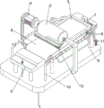
Fig. 1 is a schematic perspective view of the present invention.
Fig. 2 is a schematic perspective view of the feeding mechanism of the present invention.
Fig. 3 is a schematic perspective view of the fixing mechanism of the present invention.
Fig. 4 is a schematic perspective view of the clamping mechanism of the present invention.
Fig. 5 is a schematic perspective view of the reset mechanism of the present invention.
Fig. 6 is a schematic perspective view of the lifting mechanism of the present invention.
Fig. 7 is a schematic perspective view of the pedal mechanism of the present invention.
Fig. 8 is a schematic perspective view of the dust removing mechanism of the present invention.
Reference numbers in the drawings: 1: base, 2: sander, 3: discharge plate, 4: motor, 5: button table, 6: feeding mechanism, 61: first support bar, 62: rotating shaft, 63: conveyor belt, 64: first belt, 7: fixing mechanism, 71: second support bar, 72: bracket, 73: third support bar, 74: fixing rod, 75: first spring, 8: clamping mechanism, 81: fourth support bar, 82: splint, 83: second spring, 9: reset mechanism, 91: fifth support bar, 92: first slider, 93: third spring, 10: elevating system, 101: sixth support bar, 102: lifter plate, 103: fourth spring, 104: wedge block, 11: pedal mechanism, 111: seventh support bar, 112: second slider, 113: fifth spring, 114: a foot board, 12: dust removal mechanism, 121: eighth support bar, 122: dust removal brush, 123: a second belt.
Detailed Description
The present invention will be further described with reference to specific examples, which are illustrative of the invention and are not to be construed as limiting the invention.
Example 1
The utility model provides a new panel surface impurity equipment of polishing, as shown in fig. 1-3, including base 1, sander 2, discharging plate 3, motor 4, button platform 5, feeding mechanism 6 and fixed establishment 7, the rotary type is connected with sander 2 in the middle of the base 1 front side, be equipped with motor 4 in the middle of the base 1 rear side, motor 4 output shaft and sander 2 are connected, be equipped with feeding mechanism 6 between base 1 and the 4 output shaft of motor, discharging plate 3 has been placed on feeding mechanism 6, base 1 left side is equipped with button platform 5, button platform 5 and motor 4 pass through circuit connection, base 1 right side is equipped with fixed establishment 7.
The feeding mechanism 6 comprises first supporting rods 61, a rotating shaft 62, a conveyor belt 63 and a first belt 64, the first supporting rods 61 are arranged on four sides of the base 1, the rotating shafts 62 are rotatably connected between the first supporting rods 61 on the same longitudinal side, the conveyor belt 63 is wound between the rotating shafts 62, the discharging plate 3 is placed on the conveyor belt 63, and the first belt 64 is wound between the rotating shaft 62 on the right side and an output shaft of the motor 4.
The fixing mechanism 7 comprises a second support rod 71, a support 72, a third support rod 73, a fixing rod 74 and a first spring 75, wherein the two second support rods 71 are arranged at the right part of the base 1, the support 72 is connected between the tops of the second support rods 71, the third support rod 73 is arranged at the left front side of the top of the support 72, the fixing rod 74 is slidably connected onto the third support rod 73, and the first spring 75 is connected between the rear side of the fixing rod 74 and the third support rod 73.
When people need to polish the surface of the plate, the plate is firstly placed on the discharging plate 3, then the button on the button table 5 is manually pressed, so that the motor 4 is started, the output shaft of the motor 4 rotates to drive the sander 2 and the first belt 64 to rotate, so that the rotary shaft 62 and the conveyor belt 63 are rotated while the discharge plate 3 is blocked by the fixing rods 74, so that the plate cannot be moved leftward, and then one moves the fixing rods 74 forward, so that the first spring 75 is compressed, the discharging plate 3 and the plate move leftwards along with the conveyor belt 63, the hands are loosened, under the action of the first spring 75, the fixing rod 74 is driven to move backwards and reset, when the plate is contacted with the sander 2, the sander 2 continuously polishes the plate, can realize the effect of polishing like this, later on when the button on flitch 3 touching button platform 5 once more for motor 4 is closed, it can to take out panel.
Example 2
On the basis of the embodiment 1, as shown in fig. 4 to 8, the feeding device further comprises a clamping mechanism 8, the clamping mechanism 8 comprises a fourth supporting rod 81, a clamping plate 82 and a second spring 83, the fourth supporting rod 81 is arranged on the right front side of the feeding plate 3, the clamping plate 82 is connected to the fourth supporting rod 81 in a sliding manner, and the second spring 83 is arranged between the top of the clamping plate 82 and the fourth supporting rod 81.
When needing to fix blowing board 3, can be with splint 82 rebound for splint 82 is located conveyer belt 63 bottom, and second spring 83 is compressed, makes splint 82 and conveyer belt 63 laminate, can make blowing board 3 and conveyer belt 63 increase frictional force, so that the blowing board 3 removes about, accomplishes the back, unclamps splint 82, under the effect of second spring 83, drives splint 82 and removes and reset.
Still including canceling release mechanical system 9, canceling release mechanical system 9 is including fifth bracing piece 91, first slider 92 and third spring 93, and both sides all are connected with fifth bracing piece 91 around the 1 left part of base, and equal sliding connection has first slider 92 on the fifth bracing piece 91, all is equipped with third spring 93 between the fifth bracing piece 91 on the left side of first slider 92 and homonymy, between the first slider 92 and blowing board 3 sliding connection.
The discharging plate 3 moves leftwards, so that the third spring 93 is compressed, when the discharging plate 3 contacts the button on the button table 5, the motor 4 is turned off, and the discharging plate 3 is driven to move rightwards to reset under the action of the third spring 93.
Still including elevating system 10, elevating system 10 is equipped with sixth bracing piece 101 including sixth bracing piece 101, lifter plate 102, fourth spring 103 and wedge 104 on the right front side of base 1, and the sliding connection has lifter plate 102 on sixth bracing piece 101, and lifter plate 102 top right side is equipped with wedge 104, is connected with fourth spring 103 between lifter plate 102 bottom and the base 1.
The fixing rod 74 is moved forwards by people, so that the wedge block 104 and the lifting plate 102 move downwards, the fourth spring 103 is compressed, the clamping plate 82 is driven to move downwards to loosen the conveyor belt 63 under the action of the second spring 83, then the material discharging plate 3 is moved leftwards by a certain distance, the fixing rod 74 is loosened, the fixing rod 74 is moved backwards to reset, the wedge block 104 and the lifting plate 102 are moved upwards to reset under the action of the fourth spring 103, the lifting plate 102 enables the clamping plate 82 to move upwards to be attached to the conveyor belt 63, and friction force of the material discharging plate 3 and the conveyor belt 63 can be increased.
The pedal mechanism 11 is further included, the pedal mechanism 11 includes a seventh support rod 111, a second slider 112, a fifth spring 113 and a pedal plate 114, the two seventh support rods 111 are arranged on the right portion of the base 1, the seventh support rods 111 are all connected with the second slider 112 in a sliding manner, the fifth spring 113 is arranged between the bottom of the second slider 112 and the base 1, and the pedal plate 114 is connected between the second slider 112.
The person can step on the pedal 114 to drive the second slider 112 to move downwards, so that the fifth spring 113 is compressed, and further the fixing rod 74 moves downwards, and after the foot is released, the second slider 112 and the pedal are driven to move upwards to reset under the action of the fifth spring 113.
The dust removing device is characterized by further comprising a dust removing mechanism 12, wherein the dust removing mechanism 12 comprises an eighth supporting rod 121, a dust removing brush 122 and a second belt 123, the eighth supporting rod 121 is arranged on the middle upper portion of the front side of the base 1, the dust removing brush 122 is rotatably connected to the lower left side of the eighth supporting rod 121, and the second belt 123 is wound between the front side of the dust removing brush 122 and the sander 2.
The sander 2 continuously rotates to drive the second belt 123 and the dust removing brush 122 to rotate, so that the dust removing brush 122 continuously cleans the board.
While the disclosure has been described with respect to a limited number of embodiments, those skilled in the art, having benefit of this disclosure, will appreciate that various other embodiments can be devised which do not depart from the scope of the invention as disclosed herein. Accordingly, the scope of the invention should be limited only by the attached claims.
Claims (8)
1. The utility model provides a new panel surface impurity equipment of polishing, characterized by, including base (1), sander (2), blowing board (3), motor (4), button platform (5), feeding mechanism (6) and fixed establishment (7), base (1) one side centre rotary type is connected with sander (2), base (1) one side centre is equipped with motor (4), motor (4) output shaft and sander (2) are connected, be equipped with feeding mechanism (6) between base (1) and motor (4) output shaft, blowing board (3) have been placed on feeding mechanism (6), base (1) one side is equipped with button platform (5), button platform (5) and motor (4) pass through line connection, base (1) one side is equipped with fixed establishment (7).
2. The new plate surface impurity polishing device according to claim 1, characterized in that the feeding mechanism (6) comprises first supporting rods (61), a rotating shaft (62), a conveying belt (63) and a first belt (64), the first supporting rods (61) are arranged on four sides of the base (1), the rotating shaft (62) is rotatably connected between the first supporting rods (61) on the same longitudinal side, the conveying belt (63) is wound between the rotating shafts (62), the material placing plate (3) is placed on the conveying belt (63), and the first belt (64) is wound between the rotating shaft (62) on the right side and an output shaft of the motor (4).
3. The new plate surface impurity polishing device as claimed in claim 2, wherein the fixing mechanism (7) comprises a second support rod (71), a support (72), a third support rod (73), a fixing rod (74) and a first spring (75), two second support rods (71) are arranged at the right part of the base (1), the support (72) is connected between the tops of the second support rods (71), the third support rod (73) is arranged at one side of the top of the support (72), the fixing rod (74) is slidably connected on the third support rod (73), and the first spring (75) is connected between one side of the fixing rod (74) and the third support rod (73).
4. The new plate surface impurity polishing device according to claim 3, characterized by further comprising a clamping mechanism (8), wherein the clamping mechanism (8) comprises a fourth supporting rod (81), a clamping plate (82) and a second spring (83), the fourth supporting rod (81) is arranged on one side of the material discharging plate (3), the clamping plate (82) is connected to the fourth supporting rod (81) in a sliding mode, and the second spring (83) is arranged between the top of the clamping plate (82) and the fourth supporting rod (81).
5. The new plate surface impurity polishing device according to claim 4, characterized by further comprising a reset mechanism (9), wherein the reset mechanism (9) comprises a fifth support rod (91), a first slider (92) and a third spring (93), the fifth support rod (91) is connected to both sides of the base (1), the first slider (92) is slidably connected to the fifth support rod (91), the third spring (93) is arranged between the fifth support rod (91) on one side of the first slider (92) and on the same side, and the first sliders (92) and the material discharge plate (3) are slidably connected.
6. The new plate surface impurity grinding equipment according to claim 5, characterized by further comprising a lifting mechanism (10), wherein the lifting mechanism (10) comprises a sixth supporting rod (101), a lifting plate (102), a fourth spring (103) and a wedge block (104), the sixth supporting rod (101) is arranged on one side of the base (1), the lifting plate (102) is connected to the sixth supporting rod (101) in a sliding mode, the wedge block (104) is arranged on one side of the top of the lifting plate (102), and the fourth spring (103) is connected between the bottom of the lifting plate (102) and the base (1).
7. The new plate surface impurity polishing device according to claim 6, characterized by further comprising a pedal mechanism (11), wherein the pedal mechanism (11) comprises seventh support rods (111), second sliders (112), fifth springs (113) and pedals (114), two seventh support rods (111) are arranged at the right part of the base (1), the seventh support rods (111) are connected with the second sliders (112) in a sliding manner, the fifth springs (113) are arranged between the bottoms of the second sliders (112) and the base (1), and the pedals (114) are connected between the second sliders (112).
8. The equipment for polishing the impurities on the surface of the new plate according to claim 7, which is characterized by further comprising a dust removal mechanism (12), wherein the dust removal mechanism (12) comprises an eighth support rod (121), a dust removal brush (122) and a second belt (123), the eighth support rod (121) is arranged at the upper middle part of one side of the base (1), the dust removal brush (122) is rotatably connected to one side of the eighth support rod (121), and the second belt (123) is wound between one side of the dust removal brush (122) and the sander (2).
Priority Applications (1)
| Application Number | Priority Date | Filing Date | Title |
|---|---|---|---|
| CN202111300153.4A CN114102313B (en) | 2021-11-04 | 2021-11-04 | Novel equipment of polishing of panel surface impurity |
Applications Claiming Priority (1)
| Application Number | Priority Date | Filing Date | Title |
|---|---|---|---|
| CN202111300153.4A CN114102313B (en) | 2021-11-04 | 2021-11-04 | Novel equipment of polishing of panel surface impurity |
Publications (2)
| Publication Number | Publication Date |
|---|---|
| CN114102313A true CN114102313A (en) | 2022-03-01 |
| CN114102313B CN114102313B (en) | 2023-10-20 |
Family
ID=80380528
Family Applications (1)
| Application Number | Title | Priority Date | Filing Date |
|---|---|---|---|
| CN202111300153.4A Active CN114102313B (en) | 2021-11-04 | 2021-11-04 | Novel equipment of polishing of panel surface impurity |
Country Status (1)
| Country | Link |
|---|---|
| CN (1) | CN114102313B (en) |
Cited By (1)
| Publication number | Priority date | Publication date | Assignee | Title |
|---|---|---|---|---|
| CN114713526A (en) * | 2022-03-08 | 2022-07-08 | 钟海锋 | Building site template recovery processing equipment |
Citations (17)
| Publication number | Priority date | Publication date | Assignee | Title |
|---|---|---|---|---|
| JP2001150308A (en) * | 1999-11-26 | 2001-06-05 | Daito Seiki Kk | Surface grinding device for h-shape steel |
| US20130040541A1 (en) * | 2010-05-03 | 2013-02-14 | Inova Lisec Technologiezentrum Gmbh | Device for conveying plate-shaped elements |
| CN106346319A (en) * | 2016-09-27 | 2017-01-25 | 阳江鸿丰实业有限公司 | Belt sander feeding system |
| CN206185612U (en) * | 2016-09-27 | 2017-05-24 | 阳江鸿丰实业有限公司 | Abrasive band machine feeding system |
| CN211805340U (en) * | 2020-03-10 | 2020-10-30 | 浙江佳益自动化科技有限公司 | A fixed platform for lathe guide rail burnishing and polishing |
| CN111975537A (en) * | 2020-08-21 | 2020-11-24 | 刘兵 | Automatic feeding wood block edge grinding machine for furniture |
| CN112658901A (en) * | 2021-01-22 | 2021-04-16 | 郝慧 | Polishing equipment for connector shell protection device |
| CN112720113A (en) * | 2021-01-08 | 2021-04-30 | 周成建 | High-end equipment manufacturing steel plate surface polishing equipment |
| CN112845242A (en) * | 2021-01-15 | 2021-05-28 | 邓光明 | Solar photovoltaic panel cleaner capable of being cleaned quickly |
| CN112917334A (en) * | 2021-02-24 | 2021-06-08 | 李阳兴 | Steel pipe raw and other materials surface rust cleaning equipment for intelligent manufacturing |
| CN112975648A (en) * | 2021-02-24 | 2021-06-18 | 钟炜 | High-efficient edging device is used in daily necessities shaping |
| CN113182975A (en) * | 2021-05-12 | 2021-07-30 | 吴永辉 | Reflector manufacturing installation for bioengineering research |
| CN113211219A (en) * | 2021-05-08 | 2021-08-06 | 郭涵沫 | Plastic plate polishing equipment for mounting bottom of mounting base |
| CN113211286A (en) * | 2021-06-03 | 2021-08-06 | 陈平 | Export timber is automatic polishing equipment for furniture |
| CN113275973A (en) * | 2020-10-23 | 2021-08-20 | 江苏上玻玻璃有限公司 | Vacuum glass edging and grooving device |
| CN113305663A (en) * | 2021-05-14 | 2021-08-27 | 丁木发 | Rotary polishing equipment for manufacturing high-end equipment |
| CN113500734A (en) * | 2021-07-28 | 2021-10-15 | 游海华 | Automatic mold filling equipment for manufacturing industrial new materials |
-
2021
- 2021-11-04 CN CN202111300153.4A patent/CN114102313B/en active Active
Patent Citations (17)
| Publication number | Priority date | Publication date | Assignee | Title |
|---|---|---|---|---|
| JP2001150308A (en) * | 1999-11-26 | 2001-06-05 | Daito Seiki Kk | Surface grinding device for h-shape steel |
| US20130040541A1 (en) * | 2010-05-03 | 2013-02-14 | Inova Lisec Technologiezentrum Gmbh | Device for conveying plate-shaped elements |
| CN106346319A (en) * | 2016-09-27 | 2017-01-25 | 阳江鸿丰实业有限公司 | Belt sander feeding system |
| CN206185612U (en) * | 2016-09-27 | 2017-05-24 | 阳江鸿丰实业有限公司 | Abrasive band machine feeding system |
| CN211805340U (en) * | 2020-03-10 | 2020-10-30 | 浙江佳益自动化科技有限公司 | A fixed platform for lathe guide rail burnishing and polishing |
| CN111975537A (en) * | 2020-08-21 | 2020-11-24 | 刘兵 | Automatic feeding wood block edge grinding machine for furniture |
| CN113275973A (en) * | 2020-10-23 | 2021-08-20 | 江苏上玻玻璃有限公司 | Vacuum glass edging and grooving device |
| CN112720113A (en) * | 2021-01-08 | 2021-04-30 | 周成建 | High-end equipment manufacturing steel plate surface polishing equipment |
| CN112845242A (en) * | 2021-01-15 | 2021-05-28 | 邓光明 | Solar photovoltaic panel cleaner capable of being cleaned quickly |
| CN112658901A (en) * | 2021-01-22 | 2021-04-16 | 郝慧 | Polishing equipment for connector shell protection device |
| CN112917334A (en) * | 2021-02-24 | 2021-06-08 | 李阳兴 | Steel pipe raw and other materials surface rust cleaning equipment for intelligent manufacturing |
| CN112975648A (en) * | 2021-02-24 | 2021-06-18 | 钟炜 | High-efficient edging device is used in daily necessities shaping |
| CN113211219A (en) * | 2021-05-08 | 2021-08-06 | 郭涵沫 | Plastic plate polishing equipment for mounting bottom of mounting base |
| CN113182975A (en) * | 2021-05-12 | 2021-07-30 | 吴永辉 | Reflector manufacturing installation for bioengineering research |
| CN113305663A (en) * | 2021-05-14 | 2021-08-27 | 丁木发 | Rotary polishing equipment for manufacturing high-end equipment |
| CN113211286A (en) * | 2021-06-03 | 2021-08-06 | 陈平 | Export timber is automatic polishing equipment for furniture |
| CN113500734A (en) * | 2021-07-28 | 2021-10-15 | 游海华 | Automatic mold filling equipment for manufacturing industrial new materials |
Cited By (1)
| Publication number | Priority date | Publication date | Assignee | Title |
|---|---|---|---|---|
| CN114713526A (en) * | 2022-03-08 | 2022-07-08 | 钟海锋 | Building site template recovery processing equipment |
Also Published As
| Publication number | Publication date |
|---|---|
| CN114102313B (en) | 2023-10-20 |
Similar Documents
| Publication | Publication Date | Title |
|---|---|---|
| CN109352455B (en) | Steel pipe notch burr polisher | |
| CN112247730A (en) | Wood board deburring device for machining wood furniture | |
| CN113263363B (en) | Outer circle excess material removing device for window pulley machining | |
| CN112428038A (en) | Sanding and polishing equipment for steel basin | |
| CN114102313A (en) | New panel surface impurity equipment of polishing | |
| CN113579980A (en) | Cylindrical part excircle polishing and grinding equipment for high-end equipment | |
| CN112496956A (en) | Rotatory equipment of polishing of wooden spoon face | |
| CN112775749B (en) | Edge polishing device for fireproof motor braking system | |
| CN112157320B (en) | Automatic grinding device of rack | |
| CN114193261A (en) | Sheet metal part edge polishing equipment for new energy automobile manufacturing | |
| CN113021098B (en) | Copper facing fibre production is with to fibre surface treatment device | |
| CN116494106A (en) | Glasses frame burnishing device is used in glasses production | |
| CN112571201B (en) | Plank edge equipment of polishing | |
| CN112454082B (en) | Board grinding device for PCB circuit board processing | |
| CN112775762B (en) | Lens edge polishing equipment for industrial production | |
| CN113001284B (en) | Automatic board class article polishing machine is made to high-end | |
| CN112676948B (en) | Intelligent manufacturing steel rapid polishing equipment | |
| CN113400168A (en) | New material panel surface impurity treatment facility | |
| CN113664669A (en) | Be used for simple plane frame solder joint equipment of polishing | |
| CN115056052A (en) | Furniture manufacturing is with plank equipment of polishing | |
| CN216468746U (en) | Mobile phone film pasting device capable of quickly pasting film | |
| CN114131446A (en) | Environment-friendly grinding device of intermediate layer glass production usefulness | |
| CN113246003B (en) | Cup pad polishing equipment for wood processing | |
| CN113770895B (en) | Spot-wear processing is with polishing equipment to table tennis racket surface | |
| CN217291725U (en) | Bamboo chip burr treatment device |
Legal Events
| Date | Code | Title | Description |
|---|---|---|---|
| PB01 | Publication | ||
| PB01 | Publication | ||
| SE01 | Entry into force of request for substantive examination | ||
| SE01 | Entry into force of request for substantive examination | ||
| TA01 | Transfer of patent application right |
Effective date of registration: 20230919 Address after: 266000 Shanghe Building, No.1 Changjiang Road, Shanghe Demonstration Zone, Jiaozhou City, Qingdao City, Shandong Province (business address: Aishan Industrial Park, Yanghe Town) Applicant after: QINGDAO HAINUOWA PROFILE MANUFACTURING Co.,Ltd. Address before: 518125 room 813, 8th floor, building 3, No. 9, East Ring Road, Shajing street, Bao'an District, Guangzhou, Guangdong Applicant before: Liao Lecheng |
|
| TA01 | Transfer of patent application right | ||
| GR01 | Patent grant | ||
| GR01 | Patent grant |