CN112775749B - Edge polishing device for fireproof motor braking system - Google Patents
Edge polishing device for fireproof motor braking system Download PDFInfo
- Publication number
- CN112775749B CN112775749B CN202110024421.8A CN202110024421A CN112775749B CN 112775749 B CN112775749 B CN 112775749B CN 202110024421 A CN202110024421 A CN 202110024421A CN 112775749 B CN112775749 B CN 112775749B
- Authority
- CN
- China
- Prior art keywords
- mounting block
- block
- mounting
- base
- sliding
- Prior art date
- Legal status (The legal status is an assumption and is not a legal conclusion. Google has not performed a legal analysis and makes no representation as to the accuracy of the status listed.)
- Active
Links
Images


Classifications
-
- B—PERFORMING OPERATIONS; TRANSPORTING
- B24—GRINDING; POLISHING
- B24B—MACHINES, DEVICES, OR PROCESSES FOR GRINDING OR POLISHING; DRESSING OR CONDITIONING OF ABRADING SURFACES; FEEDING OF GRINDING, POLISHING, OR LAPPING AGENTS
- B24B9/00—Machines or devices designed for grinding edges or bevels on work or for removing burrs; Accessories therefor
-
- B—PERFORMING OPERATIONS; TRANSPORTING
- B24—GRINDING; POLISHING
- B24B—MACHINES, DEVICES, OR PROCESSES FOR GRINDING OR POLISHING; DRESSING OR CONDITIONING OF ABRADING SURFACES; FEEDING OF GRINDING, POLISHING, OR LAPPING AGENTS
- B24B41/00—Component parts such as frames, beds, carriages, headstocks
- B24B41/005—Feeding or manipulating devices specially adapted to grinding machines
-
- B—PERFORMING OPERATIONS; TRANSPORTING
- B24—GRINDING; POLISHING
- B24B—MACHINES, DEVICES, OR PROCESSES FOR GRINDING OR POLISHING; DRESSING OR CONDITIONING OF ABRADING SURFACES; FEEDING OF GRINDING, POLISHING, OR LAPPING AGENTS
- B24B41/00—Component parts such as frames, beds, carriages, headstocks
- B24B41/02—Frames; Beds; Carriages
-
- B—PERFORMING OPERATIONS; TRANSPORTING
- B24—GRINDING; POLISHING
- B24B—MACHINES, DEVICES, OR PROCESSES FOR GRINDING OR POLISHING; DRESSING OR CONDITIONING OF ABRADING SURFACES; FEEDING OF GRINDING, POLISHING, OR LAPPING AGENTS
- B24B41/00—Component parts such as frames, beds, carriages, headstocks
- B24B41/06—Work supports, e.g. adjustable steadies
-
- B—PERFORMING OPERATIONS; TRANSPORTING
- B24—GRINDING; POLISHING
- B24B—MACHINES, DEVICES, OR PROCESSES FOR GRINDING OR POLISHING; DRESSING OR CONDITIONING OF ABRADING SURFACES; FEEDING OF GRINDING, POLISHING, OR LAPPING AGENTS
- B24B47/00—Drives or gearings; Equipment therefor
- B24B47/02—Drives or gearings; Equipment therefor for performing a reciprocating movement of carriages or work- tables
- B24B47/06—Drives or gearings; Equipment therefor for performing a reciprocating movement of carriages or work- tables by liquid or gas pressure only
-
- B—PERFORMING OPERATIONS; TRANSPORTING
- B24—GRINDING; POLISHING
- B24B—MACHINES, DEVICES, OR PROCESSES FOR GRINDING OR POLISHING; DRESSING OR CONDITIONING OF ABRADING SURFACES; FEEDING OF GRINDING, POLISHING, OR LAPPING AGENTS
- B24B47/00—Drives or gearings; Equipment therefor
- B24B47/10—Drives or gearings; Equipment therefor for rotating or reciprocating working-spindles carrying grinding wheels or workpieces
- B24B47/12—Drives or gearings; Equipment therefor for rotating or reciprocating working-spindles carrying grinding wheels or workpieces by mechanical gearing or electric power
Abstract
The invention relates to a polishing device, in particular to an edge polishing device for a fireproof motor braking system. The invention aims to provide an edge grinding device for a fireproof motor braking system, which can automatically carry out polishing, has a good polishing effect and is convenient to operate. The technical scheme of the invention is that the edge grinding device for the fireproof motor braking system comprises: a base; the middle part of the base is provided with a placing mechanism; one side is equipped with grinding machanism on grinding machanism, the base. The beneficial effects are that: people place a plurality of brake blocks in proper order on the second installation piece of first conveyer belt upside for the brake block respectively with first carousel contact, then people starter motor, the output shaft of motor can drive the emery wheel and rotate, then people remove third installation piece to the left side, third installation piece can drive motor and emery wheel and remove to the left side, when the emery wheel contacted with the brake disc, makes the brake disc carry out the work of polishing.
Description
Technical Field
The invention relates to a polishing device, in particular to an edge polishing device for a fireproof motor braking system.
Background
The automobile brake pad is also called as an automobile brake shoe, generally comprises a steel plate, an adhesive heat-insulating layer and a friction block, and is a friction material fixed on a brake drum or a brake disc rotating with a wheel to generate friction action so as to achieve the aim of reducing the speed of the automobile.
When the brake block was made out, but the possible unevenness in surface perhaps has the problem of slightly rustting, consequently, surface treatment to producing this type of apparatus sets forth the requirement, it is exactly to clear away the impurity on surface thoroughly, so before the use, all can carry out the work of polishing, present polishing work generally all is that people place the brake block on the desktop, then accomplish the polishing to its surface friction with abrasive paper, the manual work is polished and probably is caused the polishing incomplete, people's work efficiency has been reduced, if the brake block of the polishing of needs is more, also can cause the condition of wasting time and energy.
Therefore, it is particularly desirable to design an edge grinding device for a fire-proof motor braking system, which automatically performs polishing, has a good polishing effect and is convenient to operate, and can eliminate most of the troubles possibly caused by manual operation, so as to improve the working efficiency and solve the above disadvantages.
Disclosure of Invention
In order to overcome the defects that incomplete polishing can be caused by manual polishing and the working efficiency of people is reduced, if the number of brake pads needing to be polished is large, time and labor are wasted, the technical problem of the invention is as follows: the edge grinding device for the fireproof motor braking system is capable of automatically polishing, good in polishing effect and convenient to operate.
The technical implementation scheme of the invention is as follows: an edge grinding device for a fireproof motor braking system, comprising: a base; the middle part of the base is provided with a placing mechanism; one side is equipped with grinding machanism on grinding machanism, the base.
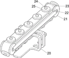
Further, the placing mechanism comprises: the mounting rack is arranged on one side of the upper middle part of the base; the upper side of the mounting frame is symmetrically provided with two first mounting blocks; the first rollers are rotatably arranged between the first mounting blocks on the same side; the first conveyor belt is connected between the first rollers; the first conveyor belt is provided with a plurality of first mounting blocks at regular intervals; first carousel, equal rotary type is equipped with first carousel on the second installation piece.
Further, the grinding mechanism comprises: a third mounting block is arranged on one side of the upper middle part of the base in a sliding manner; a motor is arranged on one side of the upper part of the third mounting block; the grinding wheel is arranged on the output shaft of the motor.
Further, still including telescopic machanism, telescopic machanism is including: a fourth mounting block is arranged on one side of the upper middle part of the base; the middle part of the base is provided with a fifth mounting block; the cylinder is arranged between the upper sides of the fourth mounting block and the fifth mounting block, and the telescopic rod of the cylinder is connected with the third mounting block.
Further, still include clamping mechanism, clamping mechanism includes: a sixth mounting block is arranged on one side of the upper middle part of the base; the sixth mounting block is provided with a second sliding block in a sliding manner; the first connecting block is arranged on one side of the first sliding block, and the first connecting block is matched with the third mounting block; a seventh mounting block is arranged on one side of the base and is in sliding fit with the first sliding block; the first spring is connected between the seventh mounting block and the first sliding block and sleeved on the first sliding block; the second connecting block is arranged between the upper sides of the mounting frames; the eighth mounting block is arranged on the upper side of the sixth mounting block; a second sliding block is arranged on one side of the upper part of the eighth mounting block in a sliding manner; the bottom of the second sliding block is rotatably provided with a third connecting block, and the lower side of the third connecting block is rotatably connected with the first sliding block; the upper part of the second sliding block is rotatably provided with a ninth mounting block; the bottom of the ninth mounting block is provided with a second turntable; a third sliding block is arranged on the lower side of the second rotary table in a sliding manner; and three second springs are connected between the second rotary disc and the third sliding block, and the second springs are sleeved on the third sliding block.
Further, still including slewing mechanism, slewing mechanism includes: a tenth mounting block is arranged at the top of the third mounting block; the tenth mounting block is rotatably provided with a first rotating shaft, and the bottom of the first rotating shaft is connected with the grinding wheel; and the third rotating disc is arranged at the top of the first rotating shaft and is matched with the second rotating disc.
Further, still include drive mechanism, drive mechanism includes: the rack is arranged on one side of the middle part of the base in a sliding manner, and the rack is matched with the third mounting block; the eleventh mounting block is arranged on one side of the upper middle part of the base; a third spring is connected between the eleventh mounting block and the rack; the upper middle part of the base is rotatably provided with a straight gear, and the straight gear and the rack are mutually meshed; a twelfth mounting block is arranged on one side of the middle part of the mounting frame; the upper middle part of the base is rotatably provided with a second rotating shaft; the middle part of the second rotating shaft is provided with a one-way gear, and the one-way gear is meshed with the straight gear; a bevel gear set is arranged between the second rotating shaft and one side of the twelfth mounting block and is rotatably connected with the twelfth mounting block; and a first transmission component is connected between one side of the twelfth mounting block and the first roller on one side.
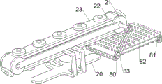
Further, still including receiving mechanism, receiving mechanism is including: a thirteenth mounting block is symmetrically arranged on one side of the base; the thirteenth mounting block is rotatably provided with a second roller; the second conveyor belt is wound between the second rollers; and a second transmission component is connected between the second roller on one side and the first roller on one side.
The invention has the beneficial effects that:
1. under grinding machanism's effect, people place a plurality of brake blocks in proper order on the second installation piece of first conveyer belt upside for the brake block contacts with first runner respectively, then people starter motor, and the output shaft of motor can drive the emery wheel and rotate, then people remove the third installation piece to the left side, and the third installation piece can drive motor and emery wheel and remove to the left side, when the emery wheel contacted with the brake disc, makes the brake disc carry out the work of polishing.
2. Under clamping mechanism's effect, when the third installation piece moves to the left side and first connecting block contact, can drive first connecting block and move to the left side, first connecting block can drive first slider and move to the left side, first slider can drive the upset of third connecting block, the third connecting block can drive the second slider, ninth installation piece, second carousel and third slider downstream, when the third slider contacts with the brake block, make the position of brake block can not squint when polishing.
3. Under receiving mechanism's effect, when first installation piece rotated, can drive the second drive assembly and rotate, the second drive assembly can drive second cylinder and second conveyer belt and rotate, and the brake block on the second installation piece can drop to the second conveyer belt because the effect of gravity, and people make more convenient receipts material work of carrying on through the second conveyer belt.
Drawings
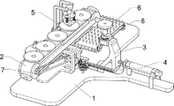
Fig. 1 is a schematic perspective view of the present invention.
FIG. 2 is a schematic view of a first partial body structure according to the present invention.
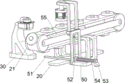
FIG. 3 is a schematic view of a second partial body structure according to the present invention.
Fig. 4 is a perspective view of a third embodiment of the present invention.
Fig. 5 is a perspective view of a fourth embodiment of the present invention.
FIG. 6 is a schematic view of a fifth partial body structure according to the present invention.
FIG. 7 is a schematic view of a sixth partial body structure according to the present invention.
FIG. 8 is a schematic view of a seventh partial body structure according to the present invention.
Fig. 9 is a schematic perspective view of an eighth partial structure of the present invention.
In the above drawings: 1: base, 2: placement mechanism, 20: mounting frame, 21: first mounting block, 22: first drum, 23: first conveyor belt, 24: second mounting block, 25: first rotary table, 3: grinding mechanism, 30: third mounting block, 31: motor, 32: grinding wheel, 4: telescoping mechanism, 40: fourth mounting block, 41: fifth mounting block, 42: cylinder, 5: clamping mechanism, 50: sixth mounting block, 51: first connection block, 52: first slider, 53: seventh mounting block, 54: first spring, 55: second connection block, 56: eighth mounting block, 57: second slider, 58: third connecting block, 59: ninth mounting block, 510: second carousel, 511: third slider, 512: second spring, 6: rotating mechanism, 60: tenth mounting block, 61: first shaft, 62: third rotary table, 7: transmission mechanism, 70: rack, 71: eleventh mounting block, 72: third spring, 73: spur gear, 74: twelfth mounting block, 75: second rotating shaft, 76: one-way gear, 77: bevel gear set, 78: first transmission assembly, 8: receiving mechanism, 80: thirteenth mounting block, 81: second roller, 82: second conveyor belt, 83: and a second transmission assembly.
Detailed Description
The invention is further described below with reference to the figures and examples.
Example 1
The utility model provides an edge grinding device for fire prevention motor braking system, as shown in figure 1, figure 2 and figure 3, including base 1, placement mechanism 2 and grinding machanism 3, the middle part is equipped with placement mechanism 2 on the base 1, and the right side is equipped with grinding machanism 3 on the base 1.
The grinding mechanism 3 comprises a third mounting block 30, a motor 31 and a grinding wheel 32, the third mounting block 30 is arranged on the right side of the upper middle part of the base 1 in a sliding mode, the motor 31 is arranged on the left side of the upper part of the third mounting block 30, and the grinding wheel 32 is arranged on an output shaft of the motor 31.
People put a plurality of brake pads on the second mounting block 24 on the upper side of the first conveyor belt 23 in sequence, so that the brake pads are respectively contacted with the first rotating disc 25, then people start the motor 31, the output shaft of the motor 31 drives the grinding wheel 32 to rotate, then people move the third mounting block 30 to the left, the third mounting block 30 drives the motor 31 and the grinding wheel 32 to move to the left, when the grinding wheel 32 is contacted with the brake disc, the brake disc is ground, after grinding of one brake disc is completed, people use a tool to rotate the first roller 22 clockwise, the first roller 22 drives the first conveyor belt 23 to rotate, the first conveyor belt 23 drives the second mounting block 24 and the brake pads on the upper side to move to the rear side, so that the grinding is carried out in sequence, after the grinding is finished, people move the third mounting block 30 to the right side, the third mounting block 30 drives the motor 31 and the grinding wheel 32 to move to the right side to reset, people can take out and collect the polished brake pads.
Example 2
On the basis of embodiment 1, as shown in fig. 4, 5, 6, 7, 8 and 9, the telescopic mechanism 4 is further included, the telescopic mechanism 4 includes a fourth mounting block 40, a fifth mounting block 41 and an air cylinder 42, the fourth mounting block 40 is arranged on the right side of the upper middle portion of the base 1, the fifth mounting block 41 is arranged on the upper middle portion of the base 1, the air cylinder 42 is arranged between the upper sides of the fourth mounting block 40 and the fifth mounting block 41, and the telescopic rod of the air cylinder 42 is connected with the third mounting block 30.
People start cylinder 42, and cylinder 42's telescopic link can drive and remove about third installation piece 30, when third installation piece 30 moved to the left side to the work of polishing is carried out automatically, the effectual work efficiency that has improved people, makes people's operation more convenient, then close cylinder 42 can.
The clamping mechanism 5 comprises a sixth mounting block 50, a first connecting block 51, a first sliding block 52, a seventh mounting block 53, a first spring 54, a second connecting block 55, an eighth mounting block 56, a second sliding block 57, a third connecting block 58, a ninth mounting block 59, a second rotary disc 510, a third sliding block 511 and a second spring 512, wherein the sixth mounting block 50 is arranged on the left side of the upper middle part of the base 1, the first sliding block 52 is arranged on the sixth mounting block 50 in a sliding manner, the first connecting block 51 is arranged on the right side of the first sliding block 52, the first connecting block 51 is matched with the third mounting block 30, the seventh mounting block 53 is arranged on the left side of the base 1, the seventh mounting block 53 is matched with the first sliding block 52 in a sliding manner, the first spring 54 is connected between the seventh mounting block 53 and the first sliding block 52, the first spring 54 is sleeved on the first sliding block 52, the second connecting block 55 is arranged between the upper sides of the mounting blocks 20, an eighth mounting block 56 is arranged on the upper side of the sixth mounting block 50, a second sliding block 57 is arranged on the right side of the upper portion of the eighth mounting block 56 in a sliding manner, a third connecting block 58 is arranged at the bottom of the second sliding block 57 in a rotating manner, the lower side of the third connecting block 58 is connected with the first sliding block 52 in a rotating manner, a ninth mounting block 59 is arranged on the upper portion of the second sliding block 57 in a rotating manner, a second rotating disc 510 is arranged at the bottom of the ninth mounting block 59, a third sliding block 511 is arranged on the lower side of the second rotating disc 510 in a sliding manner, three second springs 512 are connected between the second rotating disc 510 and the third sliding block 511, and the second springs 512 are sleeved on the third sliding block 511.
When the third mounting block 30 moves to the left to contact with the first connecting block 51, the first connecting block 51 is driven to move to the left, the first connecting block 51 drives the first slide block 52 to move to the left, the first spring 54 is compressed, the first slide block 52 drives the third connecting block 58 to turn over, the third connecting block 58 drives the second slide block 57 to move downwards, the second slide block 57 drives the ninth mounting block 59, the second rotary disc 510 and the third slide block 511 to move downwards, when the third slide block 511 contacts with the brake pad, the brake pad is clamped, so that the position of the brake pad cannot be deviated during polishing, under the buffer action of the second spring 512, the second slide block 57 cannot deform the brake pad, when the third mounting block 30 moves to the right to be separated from the first connecting block 51, under the reset action of the first spring 54, the first connecting block 51 and the first slide block 52 are driven to move to the right to be reset, the first sliding block 52 drives the third connecting block 58 to reversely turn, the third connecting block 58 drives the second sliding block 57 to move upwards, and the second sliding block 57 drives the ninth mounting block 59, the second rotating disc 510 and the third sliding block 511 to move upwards to reset.
The grinding wheel is characterized by further comprising a rotating mechanism 6, wherein the rotating mechanism 6 comprises a tenth mounting block 60, a first rotating shaft 61 and a third rotating disc 62, the tenth mounting block 60 is arranged at the top of the third mounting block 30, the tenth mounting block 60 is rotatably provided with the first rotating shaft 61, the bottom of the first rotating shaft 61 is connected with the grinding wheel 32, the third rotating disc 62 is arranged at the top of the first rotating shaft 61, and the third rotating disc 62 is matched with the second rotating disc 510.
When the grinding wheel 32 rotates, the first rotating shaft 61 and the third rotating disc 62 are driven to rotate, and meanwhile, when the third mounting block 30 moves to the left side, the first rotating shaft 61 and the third rotating disc 62 are driven to move to the left side, when the third rotating disc 62 contacts with the second rotating disc 510, the second rotating disc 510 is driven to rotate, and the second rotating disc 510 drives the third sliding block 511 and the brake pad to rotate, so that the grinding effect is better.
The automatic transmission device also comprises a transmission mechanism 7, wherein the transmission mechanism 7 comprises a rack 70, an eleventh installation block 71, a third spring 72, a straight gear 73, a twelfth installation block 74, a second rotating shaft 75, a one-way gear 76, a bevel gear group 77 and a first transmission component 78, the rack 70 is arranged on the right side of the upper middle part of the base 1 in a sliding manner, the rack 70 is matched with the third installation block 30, the eleventh installation block 71 is arranged on the left side of the upper middle part of the base 1, the third spring 72 is connected between the eleventh installation block 71 and the rack 70, the straight gear 73 is rotatably arranged on the upper middle part of the base 1, the straight gear 73 is mutually meshed with the rack 70, the twelfth installation block 74 is arranged on the right side of the middle part of the installation frame 20, the upper middle part of the base 1 is rotatably provided with a second rotating shaft 75, the middle part of the second rotating shaft 75 is provided with the one-way gear 76, the one-way gear 76 is mutually meshed with the straight gear 73, the bevel gear group 77 is arranged between the second rotating shaft 75 and the left side of the twelfth installation block 74, the bevel gear set 77 is rotatably connected to the twelfth mounting block 74, and a first transmission assembly 78 is connected between the right side and the left front side of the first roller 22 of the twelfth mounting block 74.
In an initial state, the rack 70 is in contact with the third mounting block 30, the third spring 72 is in a stretching state, when the third mounting block 30 moves to the left side and is separated from the rack 70, the rack 70 is driven to move to the left side due to the restoring action of the third spring 72, the rack 70 drives the spur gear 73 to rotate in the forward direction, the spur gear 73 does not drive the one-way gear 76 to rotate due to the action of the one-way gear 76, when the third mounting block 30 moves to the right side and is in contact with the rack 70, the rack 70 is driven to move to the right side, the third spring 72 is stretched, the rack 70 drives the spur gear 73 to rotate in the reverse direction, the spur gear 73 drives the one-way gear 76 to rotate, the one-way gear 76 drives the second rotating shaft 75 and the bevel gear set 77 to rotate, the bevel gear set 77 drives the first transmission assembly 78 to rotate, and the first transmission assembly 78 thus drives the first mounting block 21 and the first roller 22 to rotate, and then make this device push away the material automatically, effectual work efficiency who has improved people.
Still including receiving mechanism 8, receiving mechanism 8 is equipped with thirteenth installation piece 80 including thirteenth installation piece 80, second cylinder 81, second conveyer belt 82 and second drive assembly 83 in the rear side symmetry on base 1, and the equal rotary type is equipped with second cylinder 81 on the thirteenth installation piece 80, and around having second conveyer belt 82 between the second cylinder 81, be connected with second drive assembly 83 between right front side second cylinder 81 and the right rear side first cylinder 22.
When first cylinder 22 rotated, can drive second drive assembly 83 and rotate, second drive assembly 83 can drive second cylinder 81 and second conveyer belt 82 and rotate, and the brake block on the second installation piece 24 can drop to second conveyer belt 82 on because of the effect of gravity, and people make more convenient receipts material work of carrying on through second conveyer belt 82.
The above description is only an example of the present invention and is not intended to limit the present invention. All equivalents which come within the spirit of the invention are therefore intended to be embraced therein. Details not described herein are well within the skill of those in the art.
Claims (4)
1. The utility model provides an edge grinding device for fire prevention motor braking system which characterized by, including:
a base (1);
the middle part of the base (1) is provided with a placing mechanism (2);
the polishing mechanism (3) is arranged on one side of the base (1);
the placing mechanism (2) comprises:
the mounting rack (20) is arranged on one side of the upper middle part of the base (1);
the upper side of the mounting rack (20) is symmetrically provided with two first mounting blocks (21);
the first rollers (22) are rotatably arranged between the first mounting blocks (21) on the same side;
a first conveyor belt (23), the first conveyor belt (23) being connected between the first rollers (22);
the first conveyor belt (23) is provided with a plurality of first mounting blocks (24) at uniform intervals;
the first rotating disc (25) and the second mounting block (24) are respectively provided with the first rotating disc (25) in a rotating manner;
grinding machanism (3) including:
a third mounting block (30), wherein the third mounting block (30) is arranged on one side of the upper middle part of the base (1) in a sliding manner;
a motor (31), wherein the motor (31) is arranged on one side of the upper part of the third mounting block (30);
the output shaft of the motor (31) is provided with a grinding wheel (32);
still including telescopic machanism (4), telescopic machanism (4) including:
a fourth mounting block (40), wherein the fourth mounting block (40) is arranged on one side of the upper middle part of the base (1);
a fifth mounting block (41), wherein the upper middle part of the base (1) is provided with the fifth mounting block (41);
the air cylinder (42) is arranged between the upper sides of the fourth mounting block (40) and the fifth mounting block (41), and an expansion rod of the air cylinder (42) is connected with the third mounting block (30);
still including clamping mechanism (5), clamping mechanism (5) including:
a sixth mounting block (50), wherein the sixth mounting block (50) is arranged on one side of the upper middle part of the base (1);
the first sliding block (52) is arranged on the sixth mounting block (50) in a sliding mode;
the first connecting block (51) is arranged on one side of the first sliding block (52), and the first connecting block (51) is matched with the third mounting block (30);
a seventh mounting block (53), wherein the seventh mounting block (53) is arranged on one side of the base (1), and the seventh mounting block (53) is in sliding fit with the first sliding block (52);
the first spring (54) is connected between the seventh mounting block (53) and the first sliding block (52), and the first spring (54) is sleeved on the first sliding block (52);
the second connecting block (55) is arranged between the upper sides of the mounting frames (20);
an eighth mounting block (56), wherein the eighth mounting block (56) is arranged on the upper side of the sixth mounting block (50);
a second sliding block (57) is arranged on one side of the upper part of the eighth mounting block (56) in a sliding manner;
the bottom of the second sliding block (57) is rotatably provided with a third connecting block (58), and the lower side of the third connecting block (58) is rotatably connected with the first sliding block (52);
a ninth mounting block (59), wherein the upper part of the second sliding block (57) is rotatably provided with the ninth mounting block (59);
the bottom of the ninth mounting block (59) is provided with a second rotating disc (510);
a third sliding block (511), wherein the lower side of the second rotating disc (510) is provided with the third sliding block (511) in a sliding manner;
and three second springs (512) are connected between the second rotary disc (510) and the third sliding block (511), and the second springs (512) are sleeved on the third sliding block (511).
2. The edge grinding apparatus for a fire-proof motor brake system as claimed in claim 1, further comprising a rotating mechanism (6), wherein the rotating mechanism (6) comprises:
the top of the third mounting block (30) is provided with a tenth mounting block (60);
the tenth mounting block (60) is rotatably provided with a first rotating shaft (61), and the bottom of the first rotating shaft (61) is connected with the grinding wheel (32);
the top of the first rotating shaft (61) is provided with a third rotating disc (62), and the third rotating disc (62) is matched with the second rotating disc (510).
3. An edge grinding device for a fire-proof motor brake system as claimed in claim 2, further comprising a transmission mechanism (7), the transmission mechanism (7) comprising:
the rack (70) is arranged on one side of the upper middle part of the base (1) in a sliding mode, and the rack (70) is matched with the third mounting block (30);
the eleventh mounting block (71), wherein the eleventh mounting block (71) is arranged on one side of the upper middle part of the base (1);
a third spring (72), wherein the third spring (72) is connected between the eleventh mounting block (71) and the rack (70);
the upper middle part of the base (1) is rotatably provided with the straight gear (73), and the straight gear (73) is meshed with the rack (70);
a twelfth mounting block (74), wherein the twelfth mounting block (74) is arranged on one side of the middle part of the mounting rack (20);
a second rotating shaft (75), wherein the upper middle part of the base (1) is rotatably provided with the second rotating shaft (75);
the middle part of the second rotating shaft (75) is provided with a one-way gear (76), and the one-way gear (76) is meshed with the straight gear (73);
a bevel gear set (77) is arranged between the second rotating shaft (75) and one side of the twelfth mounting block (74), and the bevel gear set (77) is rotatably connected with the twelfth mounting block (74);
and a first transmission component (78) is connected between one side of the twelfth mounting block (74) and the first roller (22) on one side.
4. The edge grinding device for the fireproof motor brake system according to claim 3, further comprising a material receiving mechanism (8), wherein the material receiving mechanism (8) comprises:
a thirteenth mounting block (80), wherein the thirteenth mounting block (80) is symmetrically arranged on one side of the base (1);
the second rollers (81) are rotatably arranged on the thirteenth mounting block (80);
a second conveyor belt (82), wherein the second conveyor belt (82) is wound between the second rollers (81);
and a second transmission component (83) is connected between the second roller (81) at one side and the first roller (22) at one side.
Priority Applications (1)
| Application Number | Priority Date | Filing Date | Title |
|---|---|---|---|
| CN202110024421.8A CN112775749B (en) | 2021-01-08 | 2021-01-08 | Edge polishing device for fireproof motor braking system |
Applications Claiming Priority (1)
| Application Number | Priority Date | Filing Date | Title |
|---|---|---|---|
| CN202110024421.8A CN112775749B (en) | 2021-01-08 | 2021-01-08 | Edge polishing device for fireproof motor braking system |
Publications (2)
| Publication Number | Publication Date |
|---|---|
| CN112775749A CN112775749A (en) | 2021-05-11 |
| CN112775749B true CN112775749B (en) | 2022-01-28 |
Family
ID=75756931
Family Applications (1)
| Application Number | Title | Priority Date | Filing Date |
|---|---|---|---|
| CN202110024421.8A Active CN112775749B (en) | 2021-01-08 | 2021-01-08 | Edge polishing device for fireproof motor braking system |
Country Status (1)
| Country | Link |
|---|---|
| CN (1) | CN112775749B (en) |
Families Citing this family (2)
| Publication number | Priority date | Publication date | Assignee | Title |
|---|---|---|---|---|
| CN113400125A (en) * | 2021-05-17 | 2021-09-17 | 林永生 | Edge rounding device for circular steel ingot |
| CN113211253B (en) * | 2021-06-15 | 2022-07-05 | 漯河职业技术学院 | Brake block equipment of polishing for new energy automobile manufacturing |
Citations (11)
| Publication number | Priority date | Publication date | Assignee | Title |
|---|---|---|---|---|
| KR20170030838A (en) * | 2015-09-10 | 2017-03-20 | 한길용 | Apparatus for grinding disk |
| CN106956184A (en) * | 2017-04-11 | 2017-07-18 | 邱艳 | Efficient sanding apparatus is used in a kind of brake clutch piece production |
| CN107009233A (en) * | 2017-05-16 | 2017-08-04 | 黄东平 | A kind of brake block manufacture sanding apparatus |
| CN107097115A (en) * | 2017-05-23 | 2017-08-29 | 邱苏英 | A kind of brake block makes device for deburring |
| CN108544269A (en) * | 2018-07-03 | 2018-09-18 | 合肥连森裕腾新材料科技开发有限公司 | A kind of auto-parts production punching press drilling equipment |
| CN109176250A (en) * | 2018-08-23 | 2019-01-11 | 宁波高新区意川汽车零部件有限公司 | A kind of automotive brake pads polishing sorting equipment |
| CN209903020U (en) * | 2019-02-13 | 2020-01-07 | 沈阳永福鑫工艺品有限公司 | Fixing clamp for processing artware |
| CN210209466U (en) * | 2019-05-15 | 2020-03-31 | 天津东方瑞德机械设备有限公司 | Production frock clamp for aluminum alloy casting |
| CN212020217U (en) * | 2020-02-18 | 2020-11-27 | 浙江华力汽车配件科技有限公司 | Automobile brake pad surface grinding machine |
| CN212020336U (en) * | 2019-12-27 | 2020-11-27 | 盐城加申汽车制动部件有限公司 | Brake block grinding device |
| CN112157546A (en) * | 2020-10-28 | 2021-01-01 | 史东旭 | Circular plank edge grinding device |
Family Cites Families (2)
| Publication number | Priority date | Publication date | Assignee | Title |
|---|---|---|---|---|
| CN205888764U (en) * | 2016-08-12 | 2017-01-18 | 温州市宝饰五金制品有限公司 | Production is with high -efficient polishing device of copper |
| CN111251124A (en) * | 2020-02-29 | 2020-06-09 | 林春华 | Arc limit chair leg bracing piece grinding device |
-
2021
- 2021-01-08 CN CN202110024421.8A patent/CN112775749B/en active Active
Patent Citations (11)
| Publication number | Priority date | Publication date | Assignee | Title |
|---|---|---|---|---|
| KR20170030838A (en) * | 2015-09-10 | 2017-03-20 | 한길용 | Apparatus for grinding disk |
| CN106956184A (en) * | 2017-04-11 | 2017-07-18 | 邱艳 | Efficient sanding apparatus is used in a kind of brake clutch piece production |
| CN107009233A (en) * | 2017-05-16 | 2017-08-04 | 黄东平 | A kind of brake block manufacture sanding apparatus |
| CN107097115A (en) * | 2017-05-23 | 2017-08-29 | 邱苏英 | A kind of brake block makes device for deburring |
| CN108544269A (en) * | 2018-07-03 | 2018-09-18 | 合肥连森裕腾新材料科技开发有限公司 | A kind of auto-parts production punching press drilling equipment |
| CN109176250A (en) * | 2018-08-23 | 2019-01-11 | 宁波高新区意川汽车零部件有限公司 | A kind of automotive brake pads polishing sorting equipment |
| CN209903020U (en) * | 2019-02-13 | 2020-01-07 | 沈阳永福鑫工艺品有限公司 | Fixing clamp for processing artware |
| CN210209466U (en) * | 2019-05-15 | 2020-03-31 | 天津东方瑞德机械设备有限公司 | Production frock clamp for aluminum alloy casting |
| CN212020336U (en) * | 2019-12-27 | 2020-11-27 | 盐城加申汽车制动部件有限公司 | Brake block grinding device |
| CN212020217U (en) * | 2020-02-18 | 2020-11-27 | 浙江华力汽车配件科技有限公司 | Automobile brake pad surface grinding machine |
| CN112157546A (en) * | 2020-10-28 | 2021-01-01 | 史东旭 | Circular plank edge grinding device |
Also Published As
| Publication number | Publication date |
|---|---|
| CN112775749A (en) | 2021-05-11 |
Similar Documents
| Publication | Publication Date | Title |
|---|---|---|
| CN112775749B (en) | Edge polishing device for fireproof motor braking system | |
| CN210147714U (en) | Side grinding device | |
| CN111958464B (en) | Iron ball polishing equipment for industrial manufacturing | |
| CN108381312B (en) | Hardware circular plate polishing equipment | |
| CN109352455B (en) | Steel pipe notch burr polisher | |
| CN113579980A (en) | Cylindrical part excircle polishing and grinding equipment for high-end equipment | |
| CN206643753U (en) | Polishing machine clamping device is used in a kind of metal derby polishing | |
| CN112496956A (en) | Rotatory equipment of polishing of wooden spoon face | |
| CN112872998A (en) | High-end equipment is preliminary equipment of polishing of planar part for manufacturing | |
| CN110712105B (en) | Artificial leather polishing device | |
| CN112157320A (en) | Automatic grinding device of rack | |
| CN113021098B (en) | Copper facing fibre production is with to fibre surface treatment device | |
| CN210335368U (en) | Rubber roll is grinding device in batches | |
| CN215036330U (en) | Grinding device for industrial design | |
| CN114102313A (en) | New panel surface impurity equipment of polishing | |
| CN115194537A (en) | Manipulator is transported to material | |
| CN213829752U (en) | Brick cutting equipment | |
| CN113664657A (en) | Automatic polishing and grinding equipment for filter screen | |
| CN209175496U (en) | A kind of surface polishing device of handware processing | |
| CN113001284A (en) | High-end automatic board class article machine of polishing of making | |
| CN112809524A (en) | Machine of throwing in rotation type | |
| CN112139961A (en) | Polishing machine device capable of adjusting and adapting to undulating surface | |
| CN112571201A (en) | Plank edge equipment of polishing | |
| CN112676948A (en) | Intelligent manufacturing steel rapid grinding and polishing equipment | |
| CN112658829A (en) | Equipment of sculpture integral type is polished to iron bar |
Legal Events
| Date | Code | Title | Description |
|---|---|---|---|
| PB01 | Publication | ||
| PB01 | Publication | ||
| SE01 | Entry into force of request for substantive examination | ||
| SE01 | Entry into force of request for substantive examination | ||
| GR01 | Patent grant | ||
| GR01 | Patent grant |