CN114088727A - Automatic foundry goods surface defect detection device of upset - Google Patents
Automatic foundry goods surface defect detection device of upset Download PDFInfo
- Publication number
- CN114088727A CN114088727A CN202111521130.6A CN202111521130A CN114088727A CN 114088727 A CN114088727 A CN 114088727A CN 202111521130 A CN202111521130 A CN 202111521130A CN 114088727 A CN114088727 A CN 114088727A
- Authority
- CN
- China
- Prior art keywords
- detection
- casting
- grabbing
- matched
- main shell
- Prior art date
- Legal status (The legal status is an assumption and is not a legal conclusion. Google has not performed a legal analysis and makes no representation as to the accuracy of the status listed.)
- Granted
Links
- 238000001514 detection method Methods 0.000 title claims abstract description 90
- 230000007547 defect Effects 0.000 title claims abstract description 45
- 238000005266 casting Methods 0.000 claims abstract description 103
- 230000007246 mechanism Effects 0.000 claims abstract description 84
- 230000007306 turnover Effects 0.000 claims abstract description 59
- 230000002950 deficient Effects 0.000 claims abstract description 16
- 210000000078 claw Anatomy 0.000 claims description 22
- 238000007689 inspection Methods 0.000 claims 6
- 238000004519 manufacturing process Methods 0.000 abstract description 5
- 230000005484 gravity Effects 0.000 description 4
- 238000000034 method Methods 0.000 description 4
- 230000008901 benefit Effects 0.000 description 3
- 230000008569 process Effects 0.000 description 3
- 230000009471 action Effects 0.000 description 2
- 238000009434 installation Methods 0.000 description 2
- TVEXGJYMHHTVKP-UHFFFAOYSA-N 6-oxabicyclo[3.2.1]oct-3-en-7-one Chemical compound C1C2C(=O)OC1C=CC2 TVEXGJYMHHTVKP-UHFFFAOYSA-N 0.000 description 1
- 230000009286 beneficial effect Effects 0.000 description 1
- 230000003139 buffering effect Effects 0.000 description 1
- 230000006872 improvement Effects 0.000 description 1
- 238000012806 monitoring device Methods 0.000 description 1
- 230000000149 penetrating effect Effects 0.000 description 1
- 230000008439 repair process Effects 0.000 description 1
- 238000006467 substitution reaction Methods 0.000 description 1
Images


Classifications
-
- G—PHYSICS
- G01—MEASURING; TESTING
- G01N—INVESTIGATING OR ANALYSING MATERIALS BY DETERMINING THEIR CHEMICAL OR PHYSICAL PROPERTIES
- G01N21/00—Investigating or analysing materials by the use of optical means, i.e. using sub-millimetre waves, infrared, visible or ultraviolet light
- G01N21/84—Systems specially adapted for particular applications
- G01N21/88—Investigating the presence of flaws or contamination
- G01N21/8851—Scan or image signal processing specially adapted therefor, e.g. for scan signal adjustment, for detecting different kinds of defects, for compensating for structures, markings, edges
Landscapes
- Physics & Mathematics (AREA)
- Health & Medical Sciences (AREA)
- Life Sciences & Earth Sciences (AREA)
- Chemical & Material Sciences (AREA)
- Analytical Chemistry (AREA)
- Biochemistry (AREA)
- General Health & Medical Sciences (AREA)
- General Physics & Mathematics (AREA)
- Immunology (AREA)
- Pathology (AREA)
- Engineering & Computer Science (AREA)
- Computer Vision & Pattern Recognition (AREA)
- Signal Processing (AREA)
- Specific Conveyance Elements (AREA)
Abstract
The invention relates to the field of automatic detection of casting defects, in particular to a novel automatic turnover device for detecting casting surface defects, which comprises a pair of grabbing detection mechanisms, a vertical turnover mechanism and a conveyor belt mechanism, wherein the grabbing detection mechanisms and the vertical turnover mechanism are arranged up and down; according to the invention, the surface defects of the casting are detected twice by the grabbing detection mechanism, and the vertical turnover mechanism is arranged between the two detections to turn over the casting, so that the defect detection of the casting without dead angles in all directions can be realized; the casting with the defects can be transferred to a defective area through the grabbing detection mechanism, full automation in the field of casting defect detection is achieved, the automatic intelligent detection of the casting with high speed and high accuracy is achieved by matching with an intelligent algorithm for casting surface defect identification, the time consumption of casting surface detection is greatly shortened, the production efficiency of an enterprise is improved, the labor cost is saved, and the production cost is reduced.
Description
Technical Field
The invention relates to the field of automatic detection of casting defects, in particular to a novel automatic overturning device for detecting casting surface defects.
Background
In recent years, with the improvement of the precision requirement of the intelligent manufacturing industry on castings, casting manufacturers pay more attention to the detection of surface defects of the castings; in the traditional casting surface defect detection, six surfaces of a casting are observed in a manual detection mode, and the position and the type of the defect are determined, but the detection efficiency of the method is low, and the error detection rate is relatively high; in addition, the large casting is not easy to move during detection, so that certain danger is brought to detection personnel.
Therefore, the invention provides an automatic turnover device for detecting the surface defects of a casting; the device is used as a full-automatic detection device, can effectively detect the defect position and defect type of each surface of the casting, realizes the turnover of the casting, and has very important social significance and economic value.
Disclosure of Invention
The invention aims to provide a more reliable casting surface defect monitoring device capable of automatically overturning, and aims to solve the problems of incomplete detection surface, low detection efficiency and low automation degree in the prior art.
Based on the purpose, the invention adopts the following technical scheme:
an automatic overturning casting surface defect detection device comprises a fixed frame; a vertical turnover mechanism is arranged in the fixed frame, the vertical turnover mechanism comprises a support frame, and a turnover table is arranged on the support frame; two sides of the overturning platform are connected with hydraulic rods through rotating mechanisms, and the hydraulic rods are vertically arranged in the supporting frame; a pair of turnover bases are symmetrically arranged in the turnover table from top to bottom, and the outer sides of the pair of turnover bases are connected with the turnover bases through base hydraulic rods; two sets of grabbing detection mechanisms are arranged in the fixing frame in a matched mode with the vertical turnover mechanism, are arranged up and down and are connected with the vertical turnover mechanism through the conveying belt.
Preferably, the grabbing detection mechanism comprises a main shell, three grabbing claws are arranged on the outer side surface of the main shell in a rotational symmetry mode along the central axis of the main shell, and the angle between every two grabbing claws is 120 degrees; every snatchs the end of claw and all is provided with the industry camera, and the bottom surface of main casing body also is provided with the industry camera.
Preferably, a motor bin is arranged above the main shell, and a rotating motor is arranged in the motor bin; three hydraulic support rods are arranged in the main shell, the three hydraulic support rods are mutually rotationally and symmetrically arranged along the central axis of the main shell, and the angle between every two hydraulic support rods is 120 degrees; one end of each of the three hydraulic support rods is arranged on the top surface in the main shell; three sliding grooves are formed in the side face of the main shell, the sliding grooves are through holes which are used for penetrating the inner side space and the outer side space of the main shell, each sliding groove is obliquely arranged on the main shell, and the three sliding grooves are respectively matched with the three hydraulic supporting rods; the free ends of the three hydraulic support rods are connected with extension rods, the three extension rods penetrate through the respective matched sliding grooves to extend out of the main shell, and the tail ends of the extension rods are connected with the grabbing claws through shaft hole connection; the end of each extension rod is also connected with a hydraulic control rod, and the other end of each hydraulic control rod is connected to the side wall of the motor cabin above the main shell.
Preferably, an image processing mechanism is further arranged, the industrial camera transmits images to the image processing mechanism through signals, and a casting surface defect image detection algorithm is arranged in the image processing mechanism.
Preferably, the industrial camera arranged at the tail end of the grabbing claw is provided with a buffer rubber ring.
Preferably, the conveyor belt comprises an upper layer conveyor belt matched with the grabbing detection mechanism arranged above and a lower layer conveyor belt matched with the grabbing detection mechanism arranged below; the upper layer conveyor belt and the lower layer conveyor belt respectively comprise two conveyor belts which are respectively a detection conveyor belt and a defective product sorting belt; the top of each grabbing detection mechanism is provided with a sliding block, the sliding block is matched with a cross beam on the fixed frame, and the moving range of the sliding block on the cross beam is matched with the detection conveyor belt and the defective sorting belt; the height of the upper layer conveyor belt is matched with the highest position moved by the overturning platform, and the lower layer conveyor belt is matched with the lowest position moved by the overturning platform; the position of the detection conveyor belt is matched with the overturning platform.
Preferably, the fixed frame is provided with a lower sliding block, and the lower sliding block is arranged between the vertical turnover mechanism and the lower-layer conveyor belt; the top surface of the lower sliding block is an inclined surface, and the inclined direction of the top surface faces the direction of the lower-layer conveyor belt; and two ends of the top surface of the lower sliding block are respectively matched with the lowest position moved by the overturning platform and the detection conveyor belt in the lower layer conveyor belt.
Preferably, the other side of the vertical turnover mechanism, which is opposite to the lower sliding block, is provided with an auxiliary pushing cylinder, and the height of the auxiliary pushing cylinder is matched with the lowest height to which the turnover table moves; the piston rod end of the auxiliary pushing cylinder faces the vertical turnover mechanism, and the maximum extension position of the front end of the piston rod exceeds the farthest end of the turnover table away from the auxiliary pushing cylinder.
The invention has the following beneficial effects:
according to the automatic turnover mechanism, the casting is turned over by the automatic turnover mechanism, so that the casting can be automatically and comprehensively detected without the help of manpower, defects in the casting are found, and the defective casting is timely screened out by the help of the automatic grabbing mechanism and the automatic conveying belt; the fastest detection speed of the casting in the working process of the equipment is 20 seconds/casting, the average error detection rate is less than five percent, and compared with the traditional mode of detecting by manpower, the equipment greatly saves the manpower resource cost, increases the detection efficiency of large castings, realizes the automation of casting surface defect detection, and effectively improves the economic benefit of enterprises.
The invention has the advantages of high detection speed and more comprehensive detection; the rapid operation of the castings can be realized through the conveying and automatic overturning of the castings, the rapid and comprehensive scanning is realized, the defect positions and the defect types are rapidly determined by matching a multi-camera industrial camera and a matched intelligent image recognition system, the surface defect detection efficiency of the castings is greatly improved, and the repair work of the defective castings is facilitated.
The invention adopts a full-automatic assembly line type detection process, thereby not only improving the speed and the efficiency of detection, but also reducing the production cost of enterprises and improving the economic benefit on the basis of improving the production efficiency of the enterprises due to saving the labor and reducing the manual operation.
Drawings
FIG. 1 is a schematic view of the overall structure of embodiment 1 of the present invention;
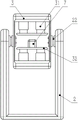
FIG. 2 is a front view of embodiment 1 of the present invention;
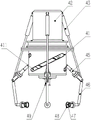
FIG. 3 is a right side view of embodiment 1 of the present invention;
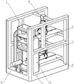
FIG. 4 is a schematic view of the overall structure of the vertical turnover mechanism of the present invention;
FIG. 5 is a front view of the vertical turnover mechanism of the present invention;
FIG. 6 is a side view in half section of the vertical turnover mechanism of the present invention;
fig. 7 is a front view of the grasping and detecting mechanism 4 in the present invention;
fig. 8 is a partial cross-sectional view of the grasping and detecting mechanism 4 in the present invention;
FIG. 9 is a schematic view of the overall structure of embodiment 2 of the present invention;
FIG. 10 is a front view of embodiment 2 of the present invention with a part of the fixing frame omitted;
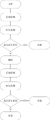
FIG. 11 is a flow chart of the present invention.
In the figure:
a fixed frame 1; a slider 11; a support frame 2; a rotating electrical machine 21; a rotating shaft 22; a lifting hydraulic rod 23; a turning table 3; the clamping hydraulic rod 31; the base 32 is turned over; a grabbing detection mechanism 4; a main housing 41; a slide slot 411; a motor compartment 42; the control hydraulic lever 43; a support hydraulic rod 44; an extension rod 45; a gripping claw 46; an industrial camera 47; a cushion rubber ring 48; a central industrial camera 49; an upper conveyor 5; an upper detection conveyer 51; an upper-level item sorting zone 52; a lower layer conveyor 6, a lower layer detection conveyor 61; a lower inferior goods sorting tape 62; a lower slider 63; a casting 7; the auxiliary pushing cylinder 8.
Detailed Description
Example 1
The following is a detailed explanation of the present invention in connection with specific embodiments; as shown in fig. 1, 2 and 3, the invention relates to a device for detecting surface defects of castings, which comprises a fixed frame 1; one end of the fixed frame 1 is provided with a vertical turnover mechanism, and two layers of conveyor belts, namely an upper layer conveyor belt 5 and a lower layer conveyor belt 6, are arranged in a way of being matched with the vertical turnover mechanism; the grabbing detection mechanism 4 is arranged above each conveyor belt mechanism, and the grabbing detection mechanism 4 is matched with the cross beam on the fixed frame 1 through the sliding block 11, so that the grabbing detection mechanism 4 can transversely move above the conveyor belts under the driving of the sliding block 41.
As shown in fig. 3, the upper and lower two groups of conveyor belts respectively include a detection conveyor belt and a defective sorting belt, the upper layer of conveyor belt 5 includes an upper detection conveyor belt 51 and an upper layer of sorting belt 52, and the lower layer of conveyor belt 6 includes a lower detection conveyor belt 61 and a lower defective sorting belt 62; wherein, two detection conveyer belts all set up with vertical tilting mechanism matched with intermediate position, and substandard product letter sorting area all sets up in the same one side position department that detects the conveyer belt.
As shown in fig. 4, 5 and 6, the vertical turnover mechanism comprises a U-shaped support frame 2, and a turnover table 3 is arranged in the middle of the support frame 2; two sides of the overturning platform 3 are respectively connected to the left side and the right side of the support frame 2 through the rotating mechanism; the rotating mechanism comprises a rotating motor 21 arranged in the support frame 2, and the rotating motor 21 is connected to the left side and the right side of the overturning platform 3 through a rotating shaft 22; the two rotating shafts 22 are driven by the rotating motor 21 connected with the rotating shafts and can rotate; through fixed block fixed connection between rotation axis and the platform of overturning 3 for the rotation axis also can drive whole platform of overturning 3 when rotatory and rotate, realizes the upset to the foundry goods 7 of placing in the platform of overturning 3.
As shown in fig. 5, a pair of symmetrically arranged clamping mechanisms is arranged inside the overturning platform 3, and each side of the pair of symmetrically arranged clamping mechanisms is composed of an overturning base 32 and a clamping hydraulic rod 31 which connects the overturning base 32 and the overturning platform 3 and is vertically arranged; when the clamping hydraulic rod 31 extends and contracts the piston rod end, the overturning base 32 connected with the piston rod end is driven to move towards the inner side direction of the overturning platform 3; when the two turning bases 32 move to a close enough distance, the casting 7 placed in the middle can be clamped and fixed for subsequent turning; rubber surfaces are arranged on the opposite inner side surfaces of the two turnover bases 32; the rubber surface can play a role in buffering when the casting 7 is clamped, and surface damage of the casting 7 caused by clamping of the turnover base is avoided.
As shown in fig. 6, the left and right vertical sections of the support frame 2 are provided with grooves on the surfaces opposite to each other, and a lifting hydraulic rod 23 is arranged in the groove of the support frame 2; the bottom end of the lifting hydraulic rod 23 is fixedly arranged at the bottom end of the inner groove of the support frame 2, and the tail end of a piston rod of the lifting hydraulic rod 23 is fixedly connected with the rotating motor 21; the rotating motor 21 is also arranged in the groove of the support frame 2, and the rotating motor 21 can move up and down in the groove under the driving of the piston rod of the lifting hydraulic rod 23, so as to drive the overturning platform 3 connected with the rotating motor 21 through the rotating shaft 22 to move up and down.
The specific structure of the grasping detection mechanism 4 is shown in fig. 7, and includes a main housing 41, where the main housing 41 is a hollow structure, and the internal structure thereof is shown in fig. 8; fig. 8 is a partially cut-away view of the main casing 41 for showing the internal configuration of the main casing 41; as shown in fig. 8, three supporting hydraulic rods 44 are disposed on the inner top surface of the main housing 41, a motor compartment is disposed above the main housing 41, and a rotating motor is disposed in the motor compartment, and can drive the main housing 41 to rotate around a central shaft, so as to drive other components of the grabbing detection mechanism 4 to perform corresponding movements; the three support hydraulic rods 44 are uniformly and rotatably arranged by taking the central axis of the main shell 41 as an axis, and the angle between every two support hydraulic rods 44 is 120 degrees; the three support hydraulic rods 44 are arranged in positions to cooperate with the rotary motor so that the rotary motor does not affect the movement of the support hydraulic rods 44 and the extension rods 45 connected thereto.
The tail end of the supporting hydraulic rod 44 is connected with an extension rod 45 in a shaft hole connection mode, three sliding grooves 411 are formed in the side face of the main shell 41, and the three sliding grooves 411 are matched with the three extension rods respectively, so that the extension rods 45 can extend out of the main shell 41 from the corresponding sliding grooves 411 respectively; the three sliding grooves 411 are arranged on the side surface of the main shell 41, similar to the three supporting hydraulic rods 44, and are also uniformly arranged in a rotating manner by taking the central axis of the main shell 41 as the axis; the angle of the space between every two sliding slots 411 is 120 degrees; the sliding slot 411 is obliquely arranged on the side surface of the main housing 41, the left side of the sliding slot 411 is lower in height, the right side of the sliding slot 411 is higher in height, and when the extension rod 45 slides in the sliding slot 411, the angle and the tail end height of the extension rod 45 are correspondingly changed due to the oblique arrangement of the sliding slot 411.
The tail end of the extension rod 45 is connected with a grabbing claw 46, the grabbing claw 46 is of an L-shaped structure, and the tail end of the grabbing claw is fixedly provided with an industrial camera 47; the head end of each industrial camera 47 is provided with a buffer rubber ring 48 which is used for directly contacting the casting 7, so that the lens of each industrial camera 47 is prevented from contacting the casting 7, and the casting 7 or the industrial camera 47 is prevented from being damaged; a central industrial camera 49 is also arranged at the bottom center of the main shell 41, the lens direction of the central industrial camera 49 is towards the vertical lower direction, three lateral industrial cameras are matched with the central industrial camera 49, five surfaces of the casting 7 except the bottom surface can be shot in detail, and images are generated for analyzing the defect condition of the casting surface.
Three control hydraulic rods 43 are arranged at the top end of the side face of the motor bin 42, the three control hydraulic rods 43 are similar to the three sliding grooves 411 and are uniformly arranged around the central axis of the main shell 41 in a rotating mode, and the distance between every two control hydraulic rods 43 is 120 degrees; the end of the piston rod of each control hydraulic rod 43 is connected to the joint of the corresponding extension rod 45 and the grabbing jaw 46; when the extension rod 45 and the grabbing claw 46 move up and down, the control hydraulic rod 43 also expands and contracts correspondingly and provides the grabbing force of the grabbing claw 46; when needed, the control hydraulic rod 43 can also actively provide hydraulic power to adjust the position and the angle of the grabbing claw 46 so as to better grab the casting 7 or adjust the shooting angle of the industrial camera 47; each industrial camera 47 is connected to the image processing mechanism by means of signal connection, and can transmit the shot image to the image processing mechanism, and the shot surface condition of the casting is analyzed by the image processing mechanism.
As shown in fig. 2, the height of the upper layer conveyor belt 5 is matched with the highest height of the overturning platform 3, so that the casting 7 conveyed on the upper layer detection conveyor belt 51 can be conveyed into a position between two overturning bases by the conveyor belt; the height of the lower layer conveyor belt 6 is matched with the lowest height of the overturning platform 3, and a lower sliding block 63 is arranged between the lower layer conveyor belt 6 and the overturning platform 3; the lower slide block 63 is a structure with an inclined top surface, the height of the higher end of the top surface is matched with the height of the overturning base when the overturning platform 3 is at the lowest height, and the height of the lower end of the top surface is matched with the height of the top surface of the lower-layer conveyor belt 6, so that the casting 7 in the overturning platform 3 can slide onto the lower-layer conveyor belt 6 through the lower slide block 63 by means of the gravity of the lower slide block when the overturning platform is at the lowest point.
In practical use, the detection flow of the embodiment is shown in fig. 11; firstly, a casting 7 to be detected is required to be placed on the upper detection conveyor belt 51; then, the conveyor belt is started, so that the casting 7 is driven by the upper detection conveyor belt 51 to move towards the vertical turnover mechanism; when the casting 7 moves below the upper grasping detection mechanism 4, the upper detecting conveyor 51 stops running, and the casting 7 starts to be detected by the grasping detection mechanism 4.
First, the rotary motor provided in the motor compartment 42 starts to operate, so that the main housing 41 starts to rotate around the shaft; when the main housing 41 starts to rotate, the three sliding grooves 411 also start to rotate around the central axis of the main housing 41; because the sliding slot 411 is arranged obliquely, the inclined angle of the extension rod arranged in the sliding slot 411 can be correspondingly changed along with the movement of the sliding slot 411, so that the tail end of the extension rod is tilted up or put down; when the lower part of the grabbing claw needs to be detected, the main shell 41 rotates anticlockwise, so that the inclination angle of each extension rod is reduced, the tail end of each extension rod descends, the grabbing claw connected with the tail end of each extension rod further descends, and the grabbing claw descends until the side surface of the casting 7 can be observed to be high through a lateral industrial camera; at this time, the side industrial camera and the central industrial camera 49 start to work, and the shot image is transmitted to the image processing mechanism; the image processing mechanism analyzes and processes the shot image file according to a built-in casting surface defect detection image algorithm, labels the surface defects existing on the casting 7 one by one, and analyzes and judges whether the defects belong to the defect within the error range; if the defect exceeding the allowable range is found, namely a command signal is sent, the gripping detection mechanism 4 is commanded to grip and place the casting on the upper-layer product sorting belt 52 aside and convey the casting to a defective area; if the defect of exceeding the allowable range does not exist, the grabbing detection mechanism 4 is reset, the upper detection conveyor belt 51 is continuously operated, and the casting 7 is conveyed to the vertical turnover mechanism.
When the casting 7 needs to be grabbed and conveyed to the defective sorting belt, the rotating motor continues to rotate, so that the main shell 41 rotates to drive the extension rod and the grabbing claws to continue to contract until the casting 7 is firmly grabbed by the tail ends of the grabbing claws; at the moment, the main shell 41 is rotated reversely, and the control hydraulic rod is extended, so that the height of the casting 7 can be lifted while the casting is firmly gripped; after the casting 7 is lifted, the sliding block 11 transversely moves on the beam of the fixed frame 1, so that the grabbing detection mechanism 4 moves to the position above the upper-level product sorting belt 52, and the steps are repeated in the opposite direction, so that the casting 7 can be placed on the upper-level product sorting belt 52; subsequently, the grabbing detection mechanism 4 resets, and the defective sorting belt can transport the casting 7 to a defective area.
If no defect is found in the first detection of the casting 7, the casting is conveyed to the vertical turnover mechanism through the upper detection conveyor belt 51; the casting 7 is conveyed into the turnover bases in the turnover table 3 by the conveyor belt, after the casting 7 is in place, the clamping hydraulic rods 31 drive the turnover bases 32, and the two turnover bases 32 move inwards under the drive of the respective clamping hydraulic rods 31 until the casting 7 is clamped between the two turnover bases 32; then, the rotating motors 21 arranged at both sides of the turning table 3 start to work, and the rotation is transmitted to the turning table 3 through the rotating shaft 22 fixedly connected with the turning table 3, so that the turning table 3 also starts to rotate; until the overturning platform 3 rotates 180 degrees, namely the upside down position is reversed, the casting 7 clamped by the overturning base is also overturned upside down.
After the casting 7 is turned over, the lifting hydraulic rod 23 starts to contract, so that the height of the turning table 3 starts to fall; when the casting falls to the lowest point, the base is overturned to release the casting 7 under the driving of the clamping hydraulic rod, and the casting 7 can slide onto the lower detection conveyor belt 61 along the path of the lower sliding block 63 under the action of self gravity; the lower detection conveyer 61 conveys the casting 7 away from the vertical turnover mechanism until the casting 7 reaches the grasping detection mechanism 4 disposed below.
When the casting 7 reaches the position below the grabbing detection mechanism 4 below the casting, the grabbing detection mechanism 4 starts to continuously perform secondary detection on the casting 7; the flow of the second detection is the same as that of the first detection, and if no defect is detected, the casting 7 is continuously conveyed by the lower detection conveyor belt 61; if a defect exceeding the error range is found on the inverted casting 7, the casting 7 is picked and placed on the lower defective sorting belt 62 by the pick and detect mechanism 4, and is conveyed to the defective area by the lower defective sorting belt 62.
Example 2
The technical solution used in this embodiment is not substantially different from the above embodiments, and the main difference is as follows: the present embodiment provides an auxiliary pushing cylinder 8 on the bottom surface of the fixing frame 1.
As shown in fig. 9, the auxiliary pushing cylinder 8 is arranged at one side of the vertical turnover mechanism and is opposite to the conveyor belt mechanism; the auxiliary pushing cylinder 8 comprises an installation table, and a cylinder is fixedly arranged at the top of the installation table; a piston rod of the air cylinder is arranged in a direction facing the vertical turnover mechanism, and a rubber pushing head is arranged at the tail end of the piston rod, so that the surface of the casting 7 is not damaged when the casting is pushed; as shown in fig. 10, the height of the mounting platform is matched with that of the overturning platform 3, so that the height of the piston rod of the cylinder is reduced to the lowest distance from the overturning platform 3, and meanwhile, the height of the overturning base 32 is matched with that of the overturning base 32 when the overturning base 32 is loosened; at this height the piston rod of the auxiliary pushing cylinder 8 can push the casting 7 placed on the turning base, pushing it towards the conveyor belt, when extended.
In use of the embodiment, after the casting 7 is placed in the vertical turnover mechanism for turnover, the turnover table 3 moves to the lowest end; at the moment, the clamping hydraulic rods on the two sides control the overturning base to loosen the casting 7, and if the casting 7 cannot move to the conveying belt along the lower sliding block 63 under the action of self gravity, the auxiliary pushing cylinder 8 can be started; the piston rod of the auxiliary pushing cylinder 8 will extend and push the casting 7 to move towards the direction of the conveyor belt until the casting 7 leaves the turning base, falls onto the lower slide block 63 and slides onto the lower detection conveyor belt 3801 through the inclined surface of the lower slide block 63; the auxiliary pushing cylinder 8 is used for providing auxiliary pushing force when the casting 7 cannot slide down by means of self gravity, and helps the casting leave the overturning base and enter the conveying belt.
The present invention is described in detail with reference to the specific embodiments, but the present invention is not limited thereto, and any changes or substitutions that can be easily made by those skilled in the art within the scope of the present invention disclosed in the present application should be covered by the protection scope of the present application, and therefore, the protection scope of the present invention should be subject to the protection scope described in the claims.
Claims (8)
1. The utility model provides an automatic foundry goods surface defect detection device of upset, includes the mount, its characterized in that: a vertical turnover mechanism is arranged in the fixed frame and comprises a support frame, and a turnover table is arranged on the support frame; two sides of the overturning platform are connected with hydraulic rods through rotating mechanisms, and the hydraulic rods are vertically arranged in the supporting frame; a pair of turnover bases are symmetrically arranged in the turnover table from top to bottom, and the outer sides of the pair of turnover bases are connected with the turnover bases through base hydraulic rods; and two sets of grabbing detection mechanisms are arranged in the fixed frame in a matching way with the vertical turnover mechanism, are arranged up and down and are connected with the vertical turnover mechanism through a conveying belt.
2. The automatically inverted casting surface defect inspection device of claim 1, wherein: the grabbing detection mechanism comprises a main shell, three grabbing claws are arranged on the outer side surface of the main shell in a rotational symmetry mode along the central axis of the main shell, and the angle between every two grabbing claws is 120 degrees; the end of each grabbing claw is provided with an industrial camera, and the bottom surface of the main shell body is also provided with an industrial camera.
3. The automatically inverted casting surface defect detecting apparatus of claim 2, wherein: a motor bin is arranged above the main shell, and a rotating motor is arranged in the motor bin; three hydraulic support rods are arranged in the main shell, the three hydraulic support rods are mutually rotationally and symmetrically arranged along the central axis of the main shell, and the angle between each two hydraulic support rods is 120 degrees; one ends of the three hydraulic support rods are all arranged on the top surface in the main shell; three sliding grooves are formed in the side face of the main shell, the sliding grooves are through holes which are communicated with the inner side space and the outer side space of the main shell, each sliding groove is obliquely arranged on the main shell, and the three sliding grooves are respectively matched with the three hydraulic supporting rods; the free ends of the three hydraulic support rods are connected with extension rods, the three extension rods penetrate through respective matched sliding grooves to extend out of the main shell, and the tail ends of the extension rods are connected with the grabbing claws through shaft hole connection; every the end of extension rod still all is connected with hydraulic control pole, every hydraulic control pole's the other end all is connected on the motor storehouse lateral wall of main casing body top.
4. The automated rotating casting surface defect inspection device of claim 3, wherein: the industrial camera transmits images to the image processing mechanism through signals, and a casting surface defect image detection algorithm is arranged in the image processing mechanism.
5. The automated rotating casting surface defect inspection device of claim 4, wherein: and a buffer rubber ring is arranged on the industrial camera arranged at the tail end of the grabbing claw.
6. The automated rotating casting surface defect inspection device of claim 5, wherein: the conveying belt comprises an upper conveying belt matched with the grabbing detection mechanism arranged above and a lower conveying belt matched with the grabbing detection mechanism arranged below; the upper-layer conveying belt and the lower-layer conveying belt respectively comprise two conveying belts which are respectively a detection conveying belt and a defective product sorting belt; the top of each grabbing detection mechanism is provided with a sliding block, the sliding block is matched with a cross beam on the fixed frame, and the moving range of the sliding block on the cross beam is matched with the detection conveyor belt and the defective sorting belt; the height of the upper layer conveyor belt is matched with the highest position moved by the overturning platform, and the height of the lower layer conveyor belt is matched with the lowest position moved by the overturning platform; the position of the detection conveyor belt is matched with the overturning platform.
7. The automated rotating casting surface defect inspection device of claim 6, wherein: the lower sliding block is arranged between the vertical turnover mechanism and the lower-layer conveyor belt; the top surface of the lower sliding block is an inclined surface, and the inclined direction of the top surface faces the direction of the lower-layer conveyor belt; and two ends of the top surface of the lower sliding block are respectively matched with the lowest position to which the overturning platform moves and the detection conveyor belt in the lower layer conveyor belt.
8. The automated rotating casting surface defect inspection device of claim 7, wherein: an auxiliary pushing cylinder is arranged on the other side, opposite to the lower sliding block, of the vertical turnover mechanism, and the height of the auxiliary pushing cylinder is matched with the lowest height to which the turnover table moves; the piston rod end of the auxiliary pushing cylinder faces the vertical turnover mechanism, and the maximum extension position of the front end of the piston rod exceeds the farthest end of the turnover table, away from the auxiliary pushing cylinder.
Priority Applications (1)
| Application Number | Priority Date | Filing Date | Title |
|---|---|---|---|
| CN202111521130.6A CN114088727B (en) | 2021-12-14 | 2021-12-14 | Automatic casting surface defect detection device that overturns |
Applications Claiming Priority (1)
| Application Number | Priority Date | Filing Date | Title |
|---|---|---|---|
| CN202111521130.6A CN114088727B (en) | 2021-12-14 | 2021-12-14 | Automatic casting surface defect detection device that overturns |
Publications (2)
| Publication Number | Publication Date |
|---|---|
| CN114088727A true CN114088727A (en) | 2022-02-25 |
| CN114088727B CN114088727B (en) | 2024-03-15 |
Family
ID=80307200
Family Applications (1)
| Application Number | Title | Priority Date | Filing Date |
|---|---|---|---|
| CN202111521130.6A Active CN114088727B (en) | 2021-12-14 | 2021-12-14 | Automatic casting surface defect detection device that overturns |
Country Status (1)
| Country | Link |
|---|---|
| CN (1) | CN114088727B (en) |
Cited By (4)
| Publication number | Priority date | Publication date | Assignee | Title |
|---|---|---|---|---|
| CN114755098A (en) * | 2022-04-29 | 2022-07-15 | 东台嘉杰精密机械有限公司 | Test equipment is used in metal casting processing |
| CN115015276A (en) * | 2022-08-01 | 2022-09-06 | 华兴智慧(北京)科技有限公司 | Workpiece inclined plane detection device for manufacturing high-end equipment |
| CN115128085A (en) * | 2022-06-27 | 2022-09-30 | 江苏科技大学 | Large-scale ring rolling spare is from inside and outside defect testing platform of horizontal upset |
| CN115228769A (en) * | 2022-08-12 | 2022-10-25 | 江西省智能产业技术创新研究院 | Automatic battery sorting system and method |
Citations (5)
| Publication number | Priority date | Publication date | Assignee | Title |
|---|---|---|---|---|
| WO2018103682A1 (en) * | 2016-12-07 | 2018-06-14 | 萨驰华辰机械(苏州)有限公司 | Device for automatically gripping steel rim and gripping method |
| CN108303429A (en) * | 2018-01-12 | 2018-07-20 | 嵊州市东浩电子科技有限公司 | It is a kind of leaded light board defect automatically detection and sorting device |
| CN109772724A (en) * | 2019-03-14 | 2019-05-21 | 溧阳市新力机械铸造有限公司 | A kind of flexible detection and analysis system of casting emphasis surface and internal flaw |
| CN110346371A (en) * | 2019-07-26 | 2019-10-18 | 重庆工商大学 | A kind of swivel nut testing agency of view-based access control model detection |
| CN110893398A (en) * | 2019-10-31 | 2020-03-20 | 中国矿业大学 | Bearing ring surface defect detection device based on machine vision |
-
2021
- 2021-12-14 CN CN202111521130.6A patent/CN114088727B/en active Active
Patent Citations (5)
| Publication number | Priority date | Publication date | Assignee | Title |
|---|---|---|---|---|
| WO2018103682A1 (en) * | 2016-12-07 | 2018-06-14 | 萨驰华辰机械(苏州)有限公司 | Device for automatically gripping steel rim and gripping method |
| CN108303429A (en) * | 2018-01-12 | 2018-07-20 | 嵊州市东浩电子科技有限公司 | It is a kind of leaded light board defect automatically detection and sorting device |
| CN109772724A (en) * | 2019-03-14 | 2019-05-21 | 溧阳市新力机械铸造有限公司 | A kind of flexible detection and analysis system of casting emphasis surface and internal flaw |
| CN110346371A (en) * | 2019-07-26 | 2019-10-18 | 重庆工商大学 | A kind of swivel nut testing agency of view-based access control model detection |
| CN110893398A (en) * | 2019-10-31 | 2020-03-20 | 中国矿业大学 | Bearing ring surface defect detection device based on machine vision |
Cited By (4)
| Publication number | Priority date | Publication date | Assignee | Title |
|---|---|---|---|---|
| CN114755098A (en) * | 2022-04-29 | 2022-07-15 | 东台嘉杰精密机械有限公司 | Test equipment is used in metal casting processing |
| CN115128085A (en) * | 2022-06-27 | 2022-09-30 | 江苏科技大学 | Large-scale ring rolling spare is from inside and outside defect testing platform of horizontal upset |
| CN115015276A (en) * | 2022-08-01 | 2022-09-06 | 华兴智慧(北京)科技有限公司 | Workpiece inclined plane detection device for manufacturing high-end equipment |
| CN115228769A (en) * | 2022-08-12 | 2022-10-25 | 江西省智能产业技术创新研究院 | Automatic battery sorting system and method |
Also Published As
| Publication number | Publication date |
|---|---|
| CN114088727B (en) | 2024-03-15 |
Similar Documents
| Publication | Publication Date | Title |
|---|---|---|
| CN114088727A (en) | Automatic foundry goods surface defect detection device of upset | |
| CN109279373B (en) | Flexible unstacking and stacking robot system and method based on machine vision | |
| CN112229844B (en) | Workpiece surface defect detection equipment | |
| CN108284360A (en) | A kind of polishing grinding workpieces system of processing | |
| CN108792612A (en) | A kind of conveying robot | |
| CN109415175B (en) | An intelligent loading and unloading system and its working method | |
| CN113735023A (en) | Timber carrying robot and timber carrying operation method | |
| CN110404803B (en) | Parallel robot sorting system and sorting method based on vision | |
| CN108772632A (en) | A kind of automatic sorting laser marking device of automobile connecting bar | |
| CN117259252A (en) | Machine vision-based surface defect detection device for disc castings and its use method | |
| CN219675812U (en) | Square energy storage battery pack appearance defect detection device | |
| CN219335013U (en) | Blade size detection machine based on CCD visual detection | |
| CN109283185B (en) | Pin detection equipment of compressor protector | |
| CN109835709A (en) | A kind of lacquer painting detection device | |
| CN111760799A (en) | A glass bottle sorting device | |
| CN108426611A (en) | Endoporus automatic detecting machine | |
| CN217191043U (en) | Sorting machine capable of achieving double-side detection | |
| CN219836830U (en) | Cylindrical battery steel shell detection equipment | |
| CN216880535U (en) | Automatic transfer control device | |
| CN110090817B (en) | Product paint surface detection device | |
| CN213226094U (en) | Automatic clamping rotating platform | |
| CN210593668U (en) | A mobile dual-arm handling device based on binocular vision | |
| CN211254373U (en) | Automatic marking automation device for differential mechanism | |
| CN211711899U (en) | Blanking device | |
| KR101153383B1 (en) | Inspection apparatus for glass plate |
Legal Events
| Date | Code | Title | Description |
|---|---|---|---|
| PB01 | Publication | ||
| PB01 | Publication | ||
| SE01 | Entry into force of request for substantive examination | ||
| SE01 | Entry into force of request for substantive examination | ||
| GR01 | Patent grant | ||
| GR01 | Patent grant |