CN114043324B - Stepping type multi-station centerless roller cylindrical grinding machine - Google Patents
Stepping type multi-station centerless roller cylindrical grinding machine Download PDFInfo
- Publication number
- CN114043324B CN114043324B CN202111442440.9A CN202111442440A CN114043324B CN 114043324 B CN114043324 B CN 114043324B CN 202111442440 A CN202111442440 A CN 202111442440A CN 114043324 B CN114043324 B CN 114043324B
- Authority
- CN
- China
- Prior art keywords
- guide wheel
- grinding
- grinding wheel
- plate
- guide
- Prior art date
- Legal status (The legal status is an assumption and is not a legal conclusion. Google has not performed a legal analysis and makes no representation as to the accuracy of the status listed.)
- Active
Links
Images

Classifications
-
- B—PERFORMING OPERATIONS; TRANSPORTING
- B24—GRINDING; POLISHING
- B24B—MACHINES, DEVICES, OR PROCESSES FOR GRINDING OR POLISHING; DRESSING OR CONDITIONING OF ABRADING SURFACES; FEEDING OF GRINDING, POLISHING, OR LAPPING AGENTS
- B24B5/00—Machines or devices designed for grinding surfaces of revolution on work, including those which also grind adjacent plane surfaces; Accessories therefor
- B24B5/02—Machines or devices designed for grinding surfaces of revolution on work, including those which also grind adjacent plane surfaces; Accessories therefor involving centres or chucks for holding work
- B24B5/04—Machines or devices designed for grinding surfaces of revolution on work, including those which also grind adjacent plane surfaces; Accessories therefor involving centres or chucks for holding work for grinding cylindrical surfaces externally
-
- B—PERFORMING OPERATIONS; TRANSPORTING
- B24—GRINDING; POLISHING
- B24B—MACHINES, DEVICES, OR PROCESSES FOR GRINDING OR POLISHING; DRESSING OR CONDITIONING OF ABRADING SURFACES; FEEDING OF GRINDING, POLISHING, OR LAPPING AGENTS
- B24B27/00—Other grinding machines or devices
- B24B27/0076—Other grinding machines or devices grinding machines comprising two or more grinding tools
-
- B—PERFORMING OPERATIONS; TRANSPORTING
- B24—GRINDING; POLISHING
- B24B—MACHINES, DEVICES, OR PROCESSES FOR GRINDING OR POLISHING; DRESSING OR CONDITIONING OF ABRADING SURFACES; FEEDING OF GRINDING, POLISHING, OR LAPPING AGENTS
- B24B27/00—Other grinding machines or devices
- B24B27/02—Bench grinders
-
- B—PERFORMING OPERATIONS; TRANSPORTING
- B24—GRINDING; POLISHING
- B24B—MACHINES, DEVICES, OR PROCESSES FOR GRINDING OR POLISHING; DRESSING OR CONDITIONING OF ABRADING SURFACES; FEEDING OF GRINDING, POLISHING, OR LAPPING AGENTS
- B24B41/00—Component parts such as frames, beds, carriages, headstocks
- B24B41/06—Work supports, e.g. adjustable steadies
- B24B41/067—Work supports, e.g. adjustable steadies radially supporting workpieces
-
- B—PERFORMING OPERATIONS; TRANSPORTING
- B24—GRINDING; POLISHING
- B24B—MACHINES, DEVICES, OR PROCESSES FOR GRINDING OR POLISHING; DRESSING OR CONDITIONING OF ABRADING SURFACES; FEEDING OF GRINDING, POLISHING, OR LAPPING AGENTS
- B24B47/00—Drives or gearings; Equipment therefor
- B24B47/02—Drives or gearings; Equipment therefor for performing a reciprocating movement of carriages or work- tables
- B24B47/06—Drives or gearings; Equipment therefor for performing a reciprocating movement of carriages or work- tables by liquid or gas pressure only
-
- B—PERFORMING OPERATIONS; TRANSPORTING
- B24—GRINDING; POLISHING
- B24B—MACHINES, DEVICES, OR PROCESSES FOR GRINDING OR POLISHING; DRESSING OR CONDITIONING OF ABRADING SURFACES; FEEDING OF GRINDING, POLISHING, OR LAPPING AGENTS
- B24B47/00—Drives or gearings; Equipment therefor
- B24B47/20—Drives or gearings; Equipment therefor relating to feed movement
-
- B—PERFORMING OPERATIONS; TRANSPORTING
- B24—GRINDING; POLISHING
- B24B—MACHINES, DEVICES, OR PROCESSES FOR GRINDING OR POLISHING; DRESSING OR CONDITIONING OF ABRADING SURFACES; FEEDING OF GRINDING, POLISHING, OR LAPPING AGENTS
- B24B53/00—Devices or means for dressing or conditioning abrasive surfaces
- B24B53/06—Devices or means for dressing or conditioning abrasive surfaces of profiled abrasive wheels
- B24B53/07—Devices or means for dressing or conditioning abrasive surfaces of profiled abrasive wheels by means of forming tools having a shape complementary to that to be produced, e.g. blocks, profile rolls
-
- B—PERFORMING OPERATIONS; TRANSPORTING
- B24—GRINDING; POLISHING
- B24B—MACHINES, DEVICES, OR PROCESSES FOR GRINDING OR POLISHING; DRESSING OR CONDITIONING OF ABRADING SURFACES; FEEDING OF GRINDING, POLISHING, OR LAPPING AGENTS
- B24B55/00—Safety devices for grinding or polishing machines; Accessories fitted to grinding or polishing machines for keeping tools or parts of the machine in good working condition
Abstract
The invention belongs to the technical field of roller grinding, and particularly relates to a stepping multi-station centerless roller cylindrical grinding machine which comprises a grinding wheel feeding device, a grinding wheel driving device, a guide wheel feeding device, a guide wheel driving device and a roller supporting device, wherein a front ejector rod and a rear ejector cylinder of the roller supporting device can move relatively to respectively push against the front end surface and the rear end surface of a roller, the grinding wheel feeding device can drive a double grinding wheel to move left and right relative to the roller to be close to or far away from the roller, the guide wheel feeding device can drive the double guide wheel to move left and right relative to the roller to be close to or far away from the roller, the double grinding wheel and double guide wheel are designed, the coaxiality of the roller after arc opening and fine grinding can be improved, the quality of a finished product is improved, the axes of the double grinding wheel can rotate for a certain angle in a horizontal plane, the axes of the double guide wheel can rotate for a certain angle in a vertical plane, the rollers of various shapes and sizes can be prevented from being secondarily clamped and processed by arc opening and fine grinding, the grinding machine can be improved in processing precision and efficiency, and is simple in adjustment and strong in applicability.
Description
Technical Field
The invention belongs to the technical field of roller grinding, and particularly relates to a stepping multi-station centerless roller cylindrical grinding machine.
Background
Circular arc or logarithmic curve roller often adopt centerless through grinding, and this kind of grinding method needs to carry out two processes of opening arc and correct grinding respectively on two grinding machines for reaching the dimensional accuracy and the surface quality requirement of roller, and roller quality stability is poor like this, and efficiency is lower, for improving roller processingquality and efficiency, needs urgently to design a marching type multistation centerless roller cylindrical grinder, has open arc and correct grinding duplex position to can adjust according to the roller of different sizes, and the adjustment is simple.
Disclosure of Invention
In order to solve the problems in the background art, the invention discloses a stepping multi-station centerless roller cylindrical grinding machine which comprises a double-grinding-wheel device, a double-guide-wheel device and a roller supporting device and is used for arc opening and fine grinding, secondary clamping during arc opening and fine grinding of a roller is avoided, machining precision and efficiency are improved, adjustment is simple, and applicability is strong.
In order to achieve the purpose, the invention adopts the following technical scheme:
the utility model provides a marching type multistation centerless roller cylindrical grinder, including two grinding wheel devices, two guide pulley devices and roller strutting arrangement, roller strutting arrangement fixed mounting is in the middle of stone workstation top, roller strutting arrangement includes front ejector pin and the back top cylinder that relative front and back set up, front ejector pin and back top cylinder can relative motion respectively withstand the front and back terminal surface of roller, two grinding wheel devices include emery wheel feeding device and emery wheel drive arrangement, emery wheel feeding device sets up the left rear end in stone workstation top, emery wheel feeding device and stone workstation swing joint, emery wheel drive arrangement sets up in emery wheel feeding device top, emery wheel drive arrangement is including setting up the left pair of emery wheel at the roller, emery wheel drive arrangement can drive two emery wheels rotatory, emery wheel feeding device can drive two emery wheels roller and move about relatively and be close or keep away from the roller, two guide pulley devices include guide pulley feeding device and guide pulley drive arrangement, guide pulley feeding device sets up the right front end in stone workstation top, guide pulley feeding device and guide pulley swing joint, guide pulley drive arrangement sets up in guide pulley feeding device top, guide pulley drive arrangement is including setting up in the two guide pulley drive arrangement on guide pulley right side, guide pulley drive arrangement, two guide pulley drive roller and move about can drive two guide pulley rotation and move about the roller and move about the stone roller and move about.
Further, two grinding wheel unit still include emery wheel type-dressing device, emery wheel type-dressing device includes that buddha's warrior attendant pen A and emery wheel type-dressing fixed plate, emery wheel type-dressing fixed plate level sets up at emery wheel feeding device top left front end, buddha's warrior attendant pen A sets up towards two emery wheels, buddha's warrior attendant pen A is through first adjusting part and emery wheel type-dressing fixed plate swing joint, under first adjusting part's effect, buddha's warrior attendant pen can be controlled around moving around the front and back relative emery wheel type-dressing fixed plate and is close or keep away from two emery wheels and carry out the type-dressing to two emery wheels.
Further, type device is repaiied to two guide pulley devices still includes the guide pulley, type device is repaiied to the guide pulley includes that the guide pulley is repaiied type bottom plate and buddha's warrior attendant pen B, type bottom plate level setting is repaiied in the guide pulley drive arrangement top to the guide pulley, buddha's warrior attendant pen B is repaiied type bottom plate swing joint through second adjusting part and guide pulley, buddha's warrior attendant pen B lower extreme is towards two guide pulleys, under second adjusting part's effect, buddha's warrior attendant pen B can be repaiied type bottom plate relative the guide pulley and remove about from about and be close or keep away from two guide pulleys and repair the type to two guide pulleys.
The roller supporting device comprises a fixed plate, a roller supporting plate, a top plate, a front ejector rod driving device, a front ejector rod and a rear ejector cylinder, wherein the fixed plate is horizontally arranged in the middle above the stone workbench, the roller supporting plate which is vertically arranged is arranged above the fixed plate, the rear ejector cylinder is arranged above the rear end of the roller supporting plate, the front ejector rod is arranged above the front end of the roller supporting plate, the front end of the rear ejector cylinder and the rear end of the front ejector rod are oppositely arranged and horizontally extend towards the roller direction respectively, the front end of the front ejector rod is in driving connection with the front ejector rod driving device through a front ejector rod fixing frame, the front end of the front ejector rod can move back and forth to be far away from or close to and abut against the front end face of the roller under the action of the front ejector rod driving device, the top plate is movably connected to the left side and the right side of the upper end of the roller supporting plate respectively, rack plates are respectively arranged on the left side and the right side of the lower end of the roller supporting plate, the bottom of each rack plate is movably connected with the fixed plate through a sliding block and a guide rail which are matched with the fixed plate respectively, the rack plate can move back and forth relative to the fixed plate, gears which are rotatably connected with the top plate respectively, and the top plate are connected with the roller supporting plate through a connecting rod mechanism when the roller lifting mechanism.
Furthermore, the grinding wheel feeding device comprises a grinding wheel feeding fixing plate, a grinding wheel feeding sliding plate and a grinding wheel feeding screw device, wherein the grinding wheel feeding fixing plate is arranged at the left rear end above the stone workbench, grinding wheel feeding guide rails extending in the left-right direction are respectively arranged on the front side and the rear side above the grinding wheel feeding fixing plate, a grinding wheel feeding sliding block matched with the grinding wheel feeding guide rails is arranged at the bottom of the grinding wheel feeding sliding plate, the grinding wheel feeding screw device is arranged in the middle above the grinding wheel feeding fixing plate, the grinding wheel feeding screw device is sleeved with a nut below the grinding wheel feeding sliding plate through a middle screw, and the grinding wheel feeding screw device can drive the grinding wheel feeding sliding plate to move left and right on the grinding wheel feeding fixing plate through a screw.
Further, the guide wheel feeding device comprises a guide wheel fixing bottom plate, a guide wheel feeding sliding plate and a screw rod, wherein the guide wheel fixing bottom plate is arranged at the right front end above the stone workbench, a lower sliding plate extending in the left-right direction is arranged above the guide wheel fixing bottom plate, a dovetail boss is arranged at the top of the lower sliding plate, an upper sliding plate matched with the lower sliding plate is arranged at the bottom of the guide wheel feeding sliding plate, the screw rod is horizontally arranged on the right side of the guide wheel fixing bottom plate in a threaded connection mode through a screw rod support, the left end of the screw rod is connected with the bottom of the guide wheel feeding sliding plate, the guide wheel feeding sliding plate can slide left and right through the rotating screw rod, L-shaped supporting plates are respectively arranged at the front end and the rear end of the guide wheel feeding sliding plate, T-shaped groove holes are respectively formed in the positions, corresponding to the bottoms of the L-shaped supporting plates, T-shaped groove screws correspondingly arranged in the T-shaped groove holes, the upper ends of the T-shaped supporting plates penetrate through the L-shaped supporting plates and are locked by nuts, and the guide wheel feeding sliding plate can be locked and positioned by locking nuts.
The grinding wheel driving device comprises a rotary bottom plate, a grinding wheel driving motor, a static pressure spindle, a rotary shaft, an adjusting screw and double grinding wheels, wherein the rotary bottom plate is arranged above a grinding wheel feeding sliding plate, the grinding wheel driving motor is arranged above the left end of the rotary bottom plate, the static pressure spindle extending in the front-back direction is arranged above the right end of the rotary bottom plate, the output end of the grinding wheel driving motor is in transmission connection with the rear end of the static pressure spindle through a transmission assembly, the double grinding wheels are sleeved at the front end of the static pressure spindle, when the grinding wheel feeding sliding plate moves left and right, the double grinding wheels can be driven to move left and right to approach or keep away from a roller through the rotary bottom plate, the vertically arranged rotary shaft is arranged between the rotary bottom plate and the middle part of the right end of the grinding wheel feeding sliding plate, rotary supports are respectively arranged on the front and back end faces of the left side of the rotary bottom plate and are connected with the grinding wheel feeding sliding plate, the adjusting screw is respectively connected with the middle part of the adjusting screw through threads, the free ends of the adjusting screw respectively extend towards the rotary bottom plate, and the rotary bottom plate can rotate around the rotary shaft to adjust the inclination angle of the double grinding wheels by adjusting screw.
Further, the guide wheel driving device comprises a guide wheel shaft support, a guide wheel rotating shaft, a guide wheel shaft and a guide wheel driving shaft device, the guide wheel shaft support is arranged above the guide wheel feeding sliding plate, the guide wheel shaft is rotatably connected with the guide wheel shaft support, a double guide wheel is sleeved at the front end of the guide wheel shaft, the rear end of the guide wheel shaft is in transmission connection with the output end of the guide wheel driving shaft device through a transmission assembly, the guide wheel driving shaft device can drive the double guide wheels to rotate through the guide wheel shaft, when the guide wheel feeding sliding plate slides left and right, the guide wheel feeding sliding plate can drive the double guide wheels to move left and right to approach or keep away from the rollers through the guide wheel shaft support and the guide wheel shaft, the guide wheel rotating shaft penetrates through the middle of the right vertical plate of the guide wheel shaft support and the middle of the right vertical plate of the guide wheel feeding sliding plate, and the guide wheel supporting seat can carry the double guide wheels to rotate around the guide wheels through the guide wheel shaft to adjust the inclination angle of the double guide wheels.
The grinding wheel dressing device comprises a grinding wheel dressing fixing plate, a grinding wheel axial dressing device, a grinding wheel radial dressing device, a diamond pen sliding plate and a diamond pen A, wherein the grinding wheel dressing fixing plate is horizontally arranged at the left front end above the rotary bottom plate, the grinding wheel axial dressing device is arranged in the middle above the grinding wheel dressing fixing plate, the grinding wheel radial dressing device is arranged above the grinding wheel axial dressing device, the grinding wheel radial dressing device is movably connected with the grinding wheel axial dressing device through a sliding block and a front-back extending guide rail which are arranged in a matching mode, the grinding wheel radial dressing device can move back and forth relative to the grinding wheel axial dressing device, the diamond pen sliding plate is movably connected with the grinding wheel radial dressing device through a sliding block and a left-right extending guide rail which are arranged in a matching mode, the diamond pen sliding plate can move left and right relative to the grinding wheel radial dressing device, the diamond pen A is arranged at the right end of the diamond pen sliding plate, the diamond pen A faces towards the double grinding wheels, and under the action of the grinding wheel axial dressing device and the grinding wheel radial dressing device, the diamond pen sliding plate can drive the diamond pen A to move back and/or move left and right relative to dress the axis dressing device to dress the excircle of the double grinding wheels.
Further, the guide wheel trimming mechanism comprises a guide wheel trimming bottom plate, a guide wheel axial trimming driving device, a guide wheel axial moving sliding plate, a guide wheel radial trimming driving device, a diamond pen fixing rod and a diamond pen B, wherein the guide wheel trimming bottom plate is arranged at the upper end of a guide wheel shaft support, a groove which is concavely arranged is formed in the middle of the upper end of the guide wheel shaft support, a boss which is matched with the groove is arranged in the middle of the lower portion of the guide wheel trimming bottom plate, the guide wheel trimming bottom plate can rotate around the boss, the guide wheel axial moving sliding plate is arranged above the guide wheel trimming bottom plate and is in sliding connection with the guide wheel trimming bottom plate, under the action of the guide wheel axial trimming driving device, the guide wheel axial moving sliding plate can slide back and forth along the guide wheel trimming bottom plate, the guide wheel radial trimming driving device is arranged above the guide wheel axial moving sliding plate, the guide wheel radial trimming driving device is connected with the upper end of a vertically arranged diamond pen fixing rod through a lead screw and a lead screw nut, the lower end of the diamond pen fixing rod passes through a linear bearing in the middle of the top of the guide wheel axial moving sliding plate, the lower end of the diamond pen fixing rod, the diamond pen fixing rod passes through the guide wheel axial moving sliding plate, the guide wheel, the lower end of the diamond pen fixing rod, the diamond pen fixing rod drives the diamond pen shaft, and drives the diamond pen fixing rod to move along the diamond pen shaft, and the diamond pen fixing rod, and drives the diamond pen shaft, and the diamond pen fixing rod under the diamond pen fixing rod, and the diamond pen shaft, and the diamond pen fixing rod, and the diamond pen shaft.
Compared with the prior art, the invention has the beneficial effects that:
1. the invention relates to a stepping multi-station centerless roller cylindrical grinding machine, which comprises a grinding wheel feeding device, a grinding wheel driving device, a guide wheel feeding device, a guide wheel driving device and a roller supporting device, wherein the roller supporting device is used for supporting and positioning a roller, two end surfaces of the roller are respectively propped by a front jacking rod and a rear jacking cylinder, the roller can be prevented from jumping during processing, the processing precision is improved, the double grinding wheels and the double guide wheels are designed, the coaxiality of the roller after arc opening and accurate grinding can be improved, the quality of a finished product is improved, the distance between the double grinding wheels and the roller can be adjusted, the axes of the double grinding wheels can rotate for a certain angle in a horizontal plane, the axes of the double guide wheels can rotate for a certain angle in a vertical plane, the grinding machine can grind the rollers with various shapes and sizes, secondary clamping of the roller during arc opening and accurate grinding can be avoided, the processing precision and efficiency can be improved, the adjustment is simple, and the applicability is strong;
2. the stepping multi-station centerless roller cylindrical grinding machine also comprises a grinding wheel shaping device and a guide wheel shaping mechanism, so that the shaping control of the grinding wheel and the guide wheel is simple, the grinding precision is high, and the outer circles of the double grinding wheel and the double guide wheel can be shaped on line according to the shape and the size of a ground roller, so that the shaping accuracy can be improved, and the grinding quality can be improved;
3. according to the stepping multi-station centerless roller cylindrical grinding machine, the diamond pen A and the double grinding wheels can synchronously rotate in the horizontal plane, and the diamond pen B and the double guide wheels can synchronously rotate in the vertical plane, so that the grinding machine can grind rollers in various shapes, and the practicability is high.
Drawings
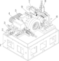
FIG. 1 is a schematic perspective view of the present invention;
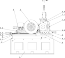
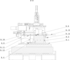
FIG. 2 is a schematic front view of the present invention;
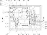
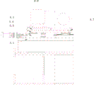
FIG. 3 is a schematic top view of the present invention;
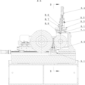
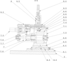
FIG. 4 isbase:Sub>A schematic sectional view A-A of FIG. 3;
FIG. 5 is a schematic cross-sectional view of B-B in FIG. 3;
FIG. 6 is a schematic cross-sectional view of D-D of FIG. 4;
FIG. 7 is a schematic cross-sectional view E-E of FIG. 2;
FIG. 8 is a perspective view of the roller support assembly of the present invention;
in the above figures: 1-a base; 2-a stone working table; 3-a grinding wheel feeding device; 4-a grinding wheel drive; 5-a grinding wheel shaping device; 6-guide wheel feeding device; 7-guide wheel driving device; 8-a guide wheel shaping mechanism; 9-roller support means; 3.1-grinding wheel feed fixing plate; 3.2-grinding wheel feed guide rail; 3.3-grinding wheel feed slide block; 3.4-grinding wheel feeding slide plate; 3.5-grinding wheel feed screw device; 4.1-rotating baseplate; 4.2-grinding wheel driving motor; 4.3-belt pulley; 4.4-belts; 4.5-hydrostatic spindle; 4.6-scaffold; 4.7-rotating shaft; 4.8-rotating the support; 4.9-adjusting screws; 4.10-double grinding wheel; 5.1-grinding wheel shaping fixing plate; 5.2-grinding wheel axial shaping device; 5.3-radial grinding wheel dressing device; 5.4-diamond pen slide; 5.5-Diamond pen A; 6.1-a guide wheel fixing bottom plate; 6.2-lower slide plate; 6.3-upper sliding plate; 6.4-T-slot screws; 6.5-nut; 6.6-guide wheel feeding slide plate; 6.7-screw support; 6.8-screw; 7.1-guide wheel shaft support; 7.2-guide wheel rotating shaft; 7.3-a guide wheel shaft; 7.4-double guide wheels; 7.5-guide wheel drive shaft device; 7.6-small belt pulley; 7.7-belts; 7.8-big belt pulley; 8.1-a guide wheel shaping bottom plate; 8.2-guide wheel axial modification driving device; 8.3-axially moving the sliding plate by the guide wheel; 8.4-radial profile modification driving device of guide wheel; 8.5-lead screw nut seat; 8.6-Diamond pen fixing rod; 8.7-linear bearing; 8.8 the diamond pen fixing block; 8.9-Diamond pen B; 9.1-fixing plate; 9.2-roller support plate; 9.3-rack plate; 9.4-cylinder; 9.5-gear; 9.6-linkage mechanism; 9.7-top plate; 9.8-rollers; 9.9-front mandril driving device; 9.10-nut seat; 9.11-front top rod; 9.12-front mandril fixing frame; 9.13-rear top cylinder; 9.14-discharge port.
Detailed Description
The technical solutions in the embodiments of the present invention will be clearly and completely described below with reference to the drawings in the embodiments of the present invention, and it is obvious that the described embodiments are only a part of the embodiments of the present invention, and not all of the embodiments. All other embodiments, which can be derived by a person skilled in the art from the embodiments given herein without making any creative effort, shall fall within the protection scope of the present invention.
The invention discloses a stepping multi-station centerless roller cylindrical grinding machine which comprises a base 1 and a stone working table 2, the double-grinding-wheel device comprises a grinding wheel feeding device 3 and a grinding wheel driving device 4, the grinding wheel feeding device 3 is fixedly arranged at the left rear end above the stone working table 2, grinding wheel drive unit 4 fixed mounting is in grinding wheel feed unit 3 top, grinding wheel drive unit 4 is including setting up two emery wheels 4.10 on roller 9.8 left side, grinding wheel drive unit 4 can drive two emery wheels 4.10 rotatory, grinding wheel feed unit 3 can drive two emery wheels 4.10 and move about relative roller 9.8 and be close to or keep away from roller 9.8, two guide pulley devices include guide pulley feed unit 6 and guide pulley drive unit 7, guide pulley feed unit 6 fixed mounting is at the right front end of stone workstation 2 top, guide pulley drive mechanism 7 fixed mounting is in guide pulley feed unit 6 top, guide pulley drive unit 7 is including setting up two guide pulleys 7.4 on roller 9.8 right side, guide pulley drive unit 7 can drive two guide pulleys 7.4 rotatory, guide pulley feed unit 6 can drive two guide pulleys 7.4 and move about relative roller 9.8 and be close to or keep away from roller 9.8.
As an optional design, preferably, the grinding wheel feeding device 3 comprises a grinding wheel feeding fixing plate 3.1, a grinding wheel feeding guide rail 3.2, a grinding wheel feeding slider 3.3, a grinding wheel feeding sliding plate 3.4 and a grinding wheel feeding screw device 3.5, wherein the grinding wheel feeding fixing plate 3.1 is fixedly installed at the left rear end above the stone worktable 2, the grinding wheel feeding guide rails 3.2 are respectively and fixedly installed on the step surfaces at the front side and the rear side above the grinding wheel feeding fixing plate, the four grinding wheel feeding sliders 3.3 are fixedly installed below the grinding wheel feeding sliding plate 3.4 and are respectively connected with the two grinding wheel feeding guide rails 3.2, the grinding wheel feeding screw device 3.5 is fixedly installed at the middle part above the grinding wheel feeding fixing plate 3.1, a screw in the middle part is sleeved with a nut below the grinding wheel feeding sliding plate 3.4, and the grinding wheel feeding screw device 3.5 drives the grinding wheel feeding sliding plate 3.4 to move left and right.
As an optional design, the grinding wheel driving device 4 preferably comprises a rotary bottom plate 4.1, a grinding wheel driving motor 4.2, a belt pulley 4.3, a belt 4.4, a static pressure main shaft 4.5, a support 4.6, a rotary shaft 4.7, a rotary support 4.8, an adjusting screw 4.9 and a double grinding wheel 4.10, wherein one grinding wheel in the double grinding wheel 4.10 is 80 grinding wheels for arc opening; the other is 240 grinding wheels for fine grinding, a rotary bottom plate 4.1 is positioned above a grinding wheel feeding sliding plate 3.4, the right ends of the two are provided with coaxial step holes, a rotary shaft 4.7 is sleeved in the holes, the rotary bottom plate 4.1 can rotate around the rotary shaft 4.7, two rotary supports 4.8 are respectively and fixedly arranged at the front side and the rear side of the left end of the grinding wheel feeding sliding plate 3.4, adjusting screws 4.9 are sleeved in screw holes above the rotary supports 4.8, the end parts of the adjusting screws 4.9 are propped against the front end surface and the rear end surface of the rotary bottom plate 4.1, the rotary bottom plate 4.1 can rotate around the rotary shaft 4.7 by adjusting the extension amount of the adjusting screws 4.9, four waist-shaped slots distributed by taking the rotary shaft 4.7 as the center are arranged on the rotary bottom plate 4.1, the adjusting screws 4.9 are rotated, the end parts of the adjusting screws 4.9 are propped against the rotary bottom plate 4.1, so that the rotary bottom plate 4.1 rotates around the rotary shaft 4.7, the double grinding wheels 4.10 are driven to rotate at a certain angle on the horizontal plane through the rotation of the rotary bottom plate 4.1 around the rotary shaft 4.7, the inclination angle of the double grinding wheels 4.10 is adjusted, when the rotary bottom plate 4.1 rotates to a required angle, the rotary bottom plate can be locked and fixed with a grinding wheel feeding sliding plate 3.4 below through a waist-shaped groove hole in the rotary bottom plate, a grinding wheel driving motor 4.2 is fixedly installed above the left end of the rotary bottom plate 4.1, belt pulleys 4.3 are fixedly sleeved on an extending shaft of the rotary bottom plate, the belt pulleys 4.3 are connected with the rear end of a static pressure main shaft 4.5 through belts 4.4, the static pressure main shaft 4.5 is fixedly sleeved in a hole in the middle of a support 4.6, two supports 4.6 are respectively and fixedly installed on the front and rear sides of the rotary bottom plate 4.1, the double grinding wheels 4.10 are fixedly sleeved at the front end of the static pressure main shaft 4.5, the grinding wheel driving motor 4.2 drives the belt pulley 4.3 to rotate, the belt pulley 4.3 drives the static pressure main shaft 4.4.4.4 to rotate through the belts 4.4.4.4, and the static pressure main shaft 4.5 drives the double grinding wheels 4.10 to rotate.
As an optional design, the double-grinding-wheel device preferably further comprises a grinding wheel dressing device 5, the grinding wheel dressing device 5 comprises a grinding wheel dressing fixing plate 5.1, a grinding wheel axial dressing device 5.2, a grinding wheel radial dressing device 5.3, a diamond pen sliding plate 5.4 and a diamond pen A5.5, the grinding wheel dressing fixing plate 5.1 is fixedly arranged at the left front end above the rotary bottom plate 4.1 and extends forwards out of the rotary bottom plate 4.1, the grinding wheel axial dressing device 5.2 is fixedly arranged in the middle above the grinding wheel dressing fixing plate 5.1, the grinding wheel radial dressing device 5.3 is arranged above the grinding wheel axial dressing device 5.2, a sliding block below the grinding wheel radial dressing device 5.3 is connected with left and right side guide rails above the grinding wheel axial dressing device 5.2, a nut below the grinding wheel radial dressing device 5.3 is connected with a lead screw in the middle of the grinding wheel axial dressing device 5.2, the front and rear sliding blocks below the diamond pen sliding plate 5.4 are connected with guide rails at the left and right ends above the grinding wheel radial shaping device 5.3, a nut below the left end of the diamond pen sliding plate 5.4 is sleeved with a lead screw in the middle of the grinding wheel radial shaping device 5.3, a diamond pen A5.5 is fixed on the right side above the grinding wheel radial shaping device 5.3, a grinding wheel axial shaping device 5.2, the grinding wheel radial shaping device 5.3 and the diamond pen sliding plate 5.4 jointly form a first adjusting component, the diamond pen A5.5 is movably connected with the grinding wheel shaping fixing plate 5.1 through the first adjusting component, under the action of the first adjusting component, the diamond pen A5.5 can move front and back and left and right relative to the grinding wheel shaping fixing plate 5.1, the grinding wheel axial shaping device 5.2 drives the grinding wheel radial shaping device 5.3 to move back and forth and back and forth, and forth and back, and forth movement of the diamond pen A5.5 is carried out axial shaping on the excircle of the double grinding wheels 4.10; the grinding wheel radial shaping device 5.3 drives the diamond pen A5.5 to move left and right and drives the diamond pen A5.5 to move left and right, the radial shaping is carried out on the excircle of the double grinding wheel 4.10, the excircle shape of the double grinding wheel 4.10 can be shaped on line according to the size and the shape required by the process of a ground roller, and the shaping of the two grinding wheels is finished by using the same diamond pen, so that the shaping accuracy can be improved, and the grinding quality is improved.
As an optional design, the guide wheel feeding device 6 preferably comprises a guide wheel fixing bottom plate 6.1, a lower sliding plate 6.2, an upper sliding plate 6.3, a T-shaped groove screw 6.4, a nut 6.5, a guide wheel feeding sliding plate 6.6, a screw rod support 6.7 and a screw rod 6.8, the guide wheel fixing bottom plate 6.1 is fixedly arranged at the right front end above the stone workbench 2, the lower sliding plate 6.2 is fixedly arranged in the middle above the guide wheel fixing bottom plate 6.1, a transverse dovetail boss is arranged above the lower sliding plate 6.2 and sleeved in a dovetail groove in the middle below the upper sliding plate 6.3, the guide wheel feeding sliding plate 6.6 is fixedly arranged above the upper sliding plate 6.3, L-shaped support plates at the front side and the rear side of the guide wheel feeding sliding plate 6.6.6 are arranged on the guide wheel fixing bottom plate 6.1, T-shaped groove holes are formed in the front side and the rear side of the guide wheel fixing bottom plate 6.1, the T-shaped groove screw rod 6.4 is arranged in L-shaped support plates at the front side and the rear side of the guide wheel feeding sliding plate 6.6.6.6.6.6, a screw rod support is sleeved in a screw rod 6.8 screw thread at the upper side of the right side of the guide wheel fixing bottom plate 6.6.6.6.6. The screw rod 6.8 is rotated to drive the guide wheel feeding sliding plate 6.6 to move left and right, and the guide wheel feeding sliding plate 6.6 can be locked and positioned through the locking nut 6.5.
As an optional design, the guide wheel driving device 7 preferably comprises a guide wheel shaft support 7.1, a guide wheel rotating shaft 7.2, a guide wheel shaft 7.3, a double guide wheel 7.4, a guide wheel driving shaft device 7.5, a small belt pulley 7.6, a belt 7.7 and a large belt pulley 7.8, wherein the double guide wheel 7.4 is used for arc opening and fine grinding, the guide wheel shaft support 7.1 is fixedly arranged above the guide wheel feeding sliding plate 6.6, a hole is arranged in the middle of a right vertical plate of the guide wheel shaft support 7.1 and is coaxial with the hole in the middle of the right vertical plate of the guide wheel feeding sliding plate 6.6, the guide wheel rotating shaft 7.2 is sleeved in the two holes, the guide wheel shaft support 7.1 can rotate around the guide wheel rotating shaft 7.2, when the guide wheel shaft support 7.1 rotates, the double guide wheel 7.4 is carried by the guide wheel shaft 7.3 to rotate for a certain angle around the rotating shaft 7.2 in a vertical plane, the inclination angle of the double guide wheel 7.4 is adjusted, four waist-shaped slotted holes are distributed on the right vertical plate of the guide wheel feeding sliding plate 6, and are matched with threaded holes distributed at four corners of the guide wheel shaft support 7.1, a screw matched with the threaded hole penetrates through the waist-shaped slotted hole and then is in threaded connection with the threaded hole to lock and fix a guide wheel shaft support 7.1 and a guide wheel feed sliding plate 6.6, the guide wheel shaft support 7.1 rotates to a certain angle around a guide wheel rotating shaft 7.2, the locking threaded hole is matched with the screw and locked by the guide wheel shaft support 7.1, a guide wheel shaft 7.3 is respectively sleeved in bearing holes at the front end, the middle end and the rear end of the guide wheel shaft support 7.1, a double guide wheel 7.4 is fixedly sleeved on a thick shaft at the front end of the guide wheel shaft 7.3, a guide wheel driving shaft device 7.5 is fixedly arranged on a step surface at the rear end of the guide wheel shaft support 7.1, a small belt pulley 7.6 is fixedly sleeved on an extending shaft of the guide wheel driving shaft device 7.5, the small belt pulley 7.6 is connected with a large belt 7.8 through the belt 7.7, the large belt 7.8 is fixedly sleeved on a shaft at the rear end of the guide wheel shaft 7.3, the guide wheel driving device 7.5 drives the small belt 7.6 to rotate, and the large belt 7.8 drives the guide wheel shaft 7.7 to rotate, the idler shaft 7.3 drives the double idler 7.4 to rotate.
As an optional design, the double-guide-wheel device preferably further comprises a guide wheel shaping mechanism 8, the guide wheel shaping mechanism 8 comprises a guide wheel shaping bottom plate 8.1, a guide wheel axial shaping driving device 8.2, a guide wheel axial moving sliding plate 8.3, a guide wheel radial shaping driving device 8.4, a screw nut seat 8.5, a diamond pen fixing rod 8.6, a linear bearing 8.7, a diamond pen fixing block 8.8 and a diamond pen B8.9, the guide wheel shaping bottom plate 8.1 is fixedly arranged on the upper end surface of the guide wheel shaft seat 7.1, a boss is arranged in the middle of the lower part of the guide wheel shaping bottom plate 8.1 and matched with a circular groove in the middle of the guide wheel shaft seat 7.1, the guide wheel shaping bottom plate 8.1 can rotate by taking the boss as a rotating shaft, two step waist-shaped slotted holes are distributed on the guide wheel shaping bottom plate 8.1 by taking the boss as the center in the front and back direction for locking and fixing the guide wheel shaping bottom plate 8.1 and the guide wheel shaft seat 7.1, the guide wheel axial shaping driving device 8.2 is fixedly arranged above the guide wheel shaping bottom plate 8.1, a guide wheel axial movement sliding plate 8.3 is positioned at the upper end of a guide wheel axial modification driving device 8.2, a threaded hole below the rear end of the guide wheel axial modification driving device is connected with a lead screw on the guide wheel axial modification driving device 8.2, a guide wheel radial modification driving device 8.4 is fixedly arranged above the guide wheel axial movement sliding plate 8.3, a hole at the right end of a lead screw nut seat 8.5 is fixedly connected with an excircle of a lead screw nut on the guide wheel radial modification driving device 8.4, a diamond pen fixing rod 8.6 is fixedly sleeved in a hole at the left end, a middle rod part of the diamond pen fixing rod 8.6 is sleeved in an inner hole of a linear bearing 8.7, the linear bearing 8.7 is fixedly sleeved in a hole at the middle of the guide wheel axial movement sliding plate 8.3, a diamond pen fixing block 8.8 is fixedly arranged in a dovetail groove at the lower end of the diamond pen fixing rod 8.6, the position of the diamond pen fixing block 8.8 in the dovetail groove is adjustable, a small hole with an inclination angle of 10-15 degrees is arranged in the middle of the diamond pen fixing block 8.8, a diamond pen B8.9 is fixedly sleeved in the hole, the guide wheel axial trimming driving device 8.2, the guide wheel axial moving sliding plate 8.3, the guide wheel radial trimming driving device and the diamond pen fixing rod 8.6 jointly form a second adjusting assembly, a diamond pen B8.9 is movably connected with the guide wheel trimming bottom plate 8.1 through the second adjusting assembly, under the action of the second adjusting assembly, the diamond pen B8.9 can move up and down, left and right relative to the guide wheel trimming bottom plate 8.1 and is close to or far away from the double guide wheels to trim the double guide wheels, and the guide wheel axial trimming driving device 8.2 drives the guide wheel axial moving sliding plate 8.3 to move back and forth to drive the diamond pen B8.9 to trim along the axial direction of the double guide wheels 7.4; the guide wheel radial shaping driving device 8.4 drives the screw nut seat 8.5 to move up and down to drive the diamond pen fixing rod 8.6 to move up and down in the inner hole of the linear bearing 8.7, so that the diamond pen B8.9 carries out shaping along the radial direction of the double guide wheel 7.4, the outer circle shape of the double guide wheel 7.4 can carry out online shaping according to the size and the shape required by the process of a grinded roller, and the two guide wheels use the same diamond pen to finish shaping, thereby improving the shaping accuracy and the grinding quality.
As an optional design, preferably, the roller supporting device 9 comprises a fixed plate 9.1, a roller supporting plate 9.2, a rack plate 9.3, a cylinder 9.4, a gear 9.5, a link mechanism 9.6, a top plate 9.7, a roller 9.8, a front ejector rod driving device 9.9, a nut seat 9.10, a front ejector rod 9.11, a front ejector rod fixing frame 9.12, a rear ejector cylinder 9.13 and a discharge port 9.14, wherein the fixed plate 9.1 is fixedly arranged on the left side above the guide wheel fixing bottom plate 6.1 and is positioned between the double grinding wheel 4.10 and the double guide wheels 7.4, the roller supporting plate 9.2 is fixedly arranged in the middle above the fixed plate 9.1, the rack plate 9.3 is fixedly arranged on guide rail sliders on the left side and the right side of the supporting plate 9.2, an extending rod of the cylinder 9.4 is fixedly connected with the front end of the rack plate 9.3, the four gears 9.5 are respectively fixedly sleeved on two rotating shafts below the supporting plate 9.2, the four roller mechanisms 9.6 are respectively fixed on the end surfaces of the four gears 9.5, the outer end surfaces of the left and right top plates 9.7, the left top plate 9.7 and the right top plate 9.7 are respectively positioned in grooves at the left side and the right side above the roller supporting plate 9.2, the roller 9.8 is positioned at the upper end of the roller supporting plate 9.2, the front mandril driving device 9.9 is fixedly arranged at the front end above the fixed plate 9.1, the screw nut is fixedly sleeved with the screw nut seat 9.10, the lower end hole of the screw nut seat 9.10 is fixedly sleeved with the front mandril 9.11, the middle of the front mandril 9.11 is sleeved in a bearing hole at the upper end of the front mandril fixing frame 9.12, the front mandril fixing frame 9.12 is fixedly arranged above the fixed plate 9.1, the foremost end of the front mandril 9.11 is propped against the front end surface of the roller 9.8, the rear jacking air cylinder 9.13 is fixedly arranged above the rear end of the fixed plate 9.1, the extending out mandril is propped against the rear end surface of the roller 9.8, the two end surfaces of the roller are respectively propped against by the front mandril 9.11 and the rear jacking air cylinder 9.13, the roller can prevent the roller from jumping during processing, the processing precision is improved, the top plate 9.7 is pushed by the air cylinder 9.4, the top plate 9.7, the roller 9.8 can conveniently slide backwards under the pushing of the front ejector rod driving device 9.9 to finish the multi-station movement of arc opening and fine grinding and the discharging movement, the surface of the roller is not easy to scratch, the discharging port 9.14 is fixedly arranged at the outer side of the rear end of the roller supporting plate 9.2, the extending rod of the cylinder 9.4 extends out of the roller supporting plate to drive the rack plate 9.3 to move forwards, the rack plate 9.3 is meshed with the gear 9.5 to rotate the gear 9.5, the connecting rod mechanism 9.6 drives the top plate 9.7 to move upwards to jack the roller 9.8 so as to enable the roller to leave the roller supporting plate 9.2, the roller 9.8 is positioned above the roller supporting plate 9.2 when the arc opening and the fine grinding are carried out, when the processing position needs to be changed, the top plate 9.7 jacks up to jack the roller 9.8 to leave the roller supporting plate 9.2, and after the grinding is finished, the front ejector rod driving device 9.9 drives the front ejector rod 9.11 to push backwards to push the roller 9.8 into the discharging port 9.14.
The working process of the invention is as follows:
before grinding, an operator firstly feeds the double guide wheels 7.4 to a grinding position, feeds the double grinding wheels 4.10 to a proper position, extends out of a cylinder 9.4 to push a rack plate 9.3 to move forwards to drive a gear 9.5 to rotate, enables a link mechanism 9.6 to jack up a top plate 9.7, places a roller 9.8 between the two top plates 9.7, drives a front ejector rod 9.11 to push backwards by a front ejector rod driving device 9.9, enables the roller 9.8 to fall down after pushing up to an arc opening station, enables the rear end of the roller 9.8 to be jacked by a rear jacking cylinder 9.13, opens a grinding wheel driving motor 4.2 and a guide wheel driving shaft device 7.5, enables the double grinding wheels 4.10 and the double guide wheels 7.4 to rotate, enables the double grinding wheels 4.10 to start feeding and grinding the roller 9.8 to be subjected to arc opening;
after the arc is opened, the grinding wheel driving motor 4.2 and the guide wheel driving shaft device 7.5 are closed, the double grinding wheels 4.10 and the double guide wheels 7.4 are stopped, the extension rod of the rear ejection cylinder 9.13 retracts, the top plate 9.7 ejects the roller 9.8, the front ejector rod driving device 9.9 drives the front ejector rod 9.11 to continuously push backwards, the roller 9.8 is ejected to a fine grinding station, the top plate 9.7 falls down, the rear ejection cylinder 9.13 ejects the rear end of the roller 9.8, the grinding wheel driving motor 4.2 and the guide wheel driving shaft device 7.5 are opened, the double grinding wheels 4.10 and the double guide wheels 7.4 start to rotate, and the double grinding wheels 4.10 start to feed and grind and finish the roller 9.8;
after finishing the fine grinding, the grinding wheel driving motor 4.2 and the guide wheel driving shaft device 7.5 are closed, the double grinding wheels 4.10 and the double guide wheels 7.4 are stopped, the extension rod of the rear ejection cylinder 9.13 retracts, the top plate 9.7 ejects the roller 9.8, the front ejector rod driving device 9.9 of the front ejector rod driving device 9.9 drives the front ejector rod 9.11 to continuously push backwards, the roller 9.8 is ejected into the discharge hole 9.14, the arc opening and the fine grinding of the excircle of the roller are simultaneously carried out, and the high forming precision, the high efficiency, the low cost and the simple adjustment of the excircle curve of the roller in the grinding process can be ensured.
In the description of the present invention, it should be noted that the terms "center", "upper", "lower", "left", "right", "vertical", "horizontal", "front", "rear", etc. indicate orientations or positional relationships based on the orientations or positional relationships shown in the drawings, which are only for convenience of description and simplicity of description, but do not indicate or imply that the designated devices or elements must have specific orientations, be constructed and operated in specific orientations, and therefore, should not be construed as limiting the present invention.
It will be evident to those skilled in the art that the invention is not limited to the details of the foregoing illustrative embodiments, and that the present invention may be embodied in other specific forms without departing from the spirit or essential attributes thereof. The present embodiments are therefore to be considered in all respects as illustrative and not restrictive, the scope of the invention being indicated by the appended claims rather than by the foregoing description, and all changes which come within the meaning and range of equivalency of the claims are therefore intended to be embraced therein, and any reference signs in the claims are not intended to be construed as limiting the claim concerned.
Furthermore, it should be understood that although the present description refers to embodiments, not every embodiment may contain only a single embodiment, and such description is for clarity only, and those skilled in the art should integrate the description, and the embodiments may be combined as appropriate to form other embodiments understood by those skilled in the art.
Claims (8)
1. The utility model provides a marching type multistation centerless roller cylindrical grinder which characterized by: the double-guide wheel device comprises a double-grinding wheel device, a double-guide wheel device and a roller supporting device;
the roller supporting device is fixedly arranged in the middle above the stone working table and comprises a front ejector rod and a rear ejection cylinder which are arranged oppositely from front to back, and the front ejector rod and the rear ejection cylinder can move relatively to respectively eject against the front end surface and the rear end surface of the roller;
the double-grinding-wheel device comprises a grinding wheel feeding device, a grinding wheel driving device and a grinding wheel dressing device, wherein the grinding wheel feeding device comprises a grinding wheel feeding fixed plate arranged at the left rear end above the stone workbench and a grinding wheel feeding sliding plate arranged at the top of the grinding wheel feeding fixed plate and movably connected with the grinding wheel feeding fixed plate, the grinding wheel driving device is arranged above the grinding wheel feeding device, the grinding wheel driving device comprises double grinding wheels arranged at the left side of a roller, the grinding wheel driving device can drive the double grinding wheels to rotate, the grinding wheel feeding sliding plate can move left and right relative to the grinding wheel feeding fixed plate and drive the double grinding wheels to move left and right relative to the roller to be close to or far away from the roller, a rotary bottom plate is arranged above the grinding wheel feeding sliding plate, a vertically arranged rotary shaft is arranged between the rotary bottom plate and the middle part of the right end of the grinding wheel feeding sliding plate, rotary supports are respectively arranged on the front and rear end surfaces at the left side of the rotary bottom plate, and are connected with the grinding wheel feeding sliding plate, adjusting screws are respectively connected to the middle of the rotary support through threads, free ends of the adjusting screws extend towards the direction of the rotary bottom plate respectively, the rotary bottom plate can rotate around a rotary shaft to adjust the inclination angle of the double grinding wheels by adjusting the extension amount of the adjusting screws, the grinding wheel dressing device comprises a grinding wheel dressing fixing plate, a grinding wheel axial dressing device, a grinding wheel radial dressing device, a diamond pen sliding plate and a diamond pen A, the grinding wheel dressing fixing plate is horizontally arranged at the left front end above the rotary bottom plate, the grinding wheel axial dressing device is arranged in the middle above the grinding wheel dressing fixing plate, a grinding wheel radial dressing device is arranged above the grinding wheel axial dressing device, the grinding wheel radial dressing device is movably connected with the grinding wheel axial dressing device through a sliding block and a front-back extending guide rail which are arranged in a matching mode, and can move back and forth relative to the grinding wheel axial dressing device, the diamond pen sliding plate is movably connected with the grinding wheel radial shaping device through a sliding block and a left and right extending guide rail which are arranged in a matched mode, the diamond pen sliding plate can move left and right relative to the grinding wheel radial shaping device, a diamond pen A is arranged at the right end of the diamond pen sliding plate and faces towards the double grinding wheels, and under the action of the grinding wheel axial shaping device and the grinding wheel radial shaping device, the diamond pen sliding plate can drive the diamond pen A to move front and back and/or left and right to shape the excircle of the double grinding wheels in the axial direction and/or the radial direction;
the double-guide-wheel device comprises a guide wheel feeding device and a guide wheel driving device, the guide wheel feeding device comprises a guide wheel fixing bottom plate and a guide wheel feeding sliding plate, the guide wheel fixing bottom plate is arranged at the right front end above the stone workbench, a lower sliding plate extending in the left-right direction is arranged above the guide wheel fixing bottom plate, the guide wheel feeding sliding plate is movably connected with the lower sliding plate, the guide wheel driving device is arranged above the guide wheel feeding sliding plate, the guide wheel driving device comprises double guide wheels arranged on the right side of a roller, a guide wheel shaft support is arranged above the guide wheel feeding sliding plate, the guide wheel shaft is rotatably connected with a guide wheel shaft support, the front end of the guide wheel shaft is sleeved with the double guide wheels, the guide wheel driving device can drive the double guide wheels to rotate, when the guide wheel feeding sliding plate slides left and right, the double guide wheels can be driven to move left and right through the guide wheel shaft support and the guide wheel shaft to be close to or far away from the roller, rotating shafts are arranged in the middle of a right vertical plate of the guide wheel support, and rotating shafts can carry the double guide wheels to rotate around the rotating shafts to adjust the inclination angle of the double guide wheels.
2. The stepping multi-station centerless roller cylindrical grinding machine of claim 1, wherein: the double-guide-wheel device further comprises a guide wheel trimming device, the guide wheel trimming device comprises a guide wheel trimming bottom plate and a diamond pen B, the guide wheel trimming bottom plate is horizontally arranged above the guide wheel driving device, the diamond pen B is movably connected with the guide wheel trimming bottom plate through a second adjusting assembly, the lower end of the diamond pen B faces towards the double guide wheels, and under the action of the second adjusting assembly, the diamond pen B can move up and down relative to the guide wheel trimming bottom plate and is close to or far away from the double guide wheels to trim the double guide wheels.
3. The stepping multi-station centerless roller cylindrical grinding machine of claim 2, wherein: the roller supporting device comprises a fixed plate, a roller supporting plate, a top plate, a front ejector rod driving device, a front ejector rod and a rear ejector cylinder, wherein the fixed plate is horizontally arranged in the middle of the upper portion of a stone workbench, the roller supporting plate which is vertically arranged is arranged above the fixed plate, the rear ejector cylinder is arranged above the rear end of the roller supporting plate, the front end of the rear ejector cylinder and the rear end of the front ejector rod are oppositely arranged and horizontally extend towards the roller direction respectively, the front end of the front ejector rod is in driving connection with the front ejector rod driving device through a front ejector rod fixing frame, the front end of the front ejector rod can move back and forth to be far away from or close to and abut against the front end face of the roller under the action of the front ejector rod driving device, the top plate is movably connected to the left side and the right side of the upper end of the roller supporting plate respectively, rack plates are respectively arranged on the left side and the right side of the lower end of the roller supporting plate, the bottom of each rack plate is movably connected with the fixed plate through a sliding block and a guide rail which are matched with each other, the rack plate can move back and forth relative to the fixed plate, gears which are rotatably connected with the gear plate in a roller lifting mechanism through a connecting rod and a roller driving mechanism when the roller.
4. The stepping multi-station centerless roller cylindrical grinding machine of claim 3, wherein: the grinding wheel feeding device also comprises a grinding wheel feeding screw device, grinding wheel feeding guide rails extending in the left-right direction are respectively arranged on the front side and the rear side above the grinding wheel feeding fixing plate, a grinding wheel feeding slide block matched with the grinding wheel feeding guide rails is arranged at the bottom of the grinding wheel feeding slide plate, the grinding wheel feeding screw device is arranged in the middle above the grinding wheel feeding fixing plate, the grinding wheel feeding screw device is sleeved with a nut below the grinding wheel feeding slide plate through a screw in the middle, and the grinding wheel feeding screw device can drive the grinding wheel feeding slide plate to move left and right on the grinding wheel feeding fixing plate through a screw.
5. The stepping multi-station centerless roller cylindrical grinding machine of claim 3, wherein: the guide wheel feeding device further comprises a screw, a dovetail boss is arranged at the top of the lower sliding plate, an upper sliding plate matched with the lower sliding plate is arranged at the bottom of the guide wheel feeding sliding plate, a horizontally arranged screw is connected to the right side of the guide wheel fixing bottom plate through a screw support in a threaded manner, the left end of the screw is connected with the bottom of the guide wheel feeding sliding plate, the guide wheel feeding sliding plate can slide left and right along the lower sliding plate by rotating the screw, L-shaped supporting plates are respectively arranged at the front end and the rear end of the guide wheel feeding sliding plate, T-shaped slotted holes are respectively formed in the positions, corresponding to the bottoms of the L-shaped supporting plates, of the guide wheel fixing bottom plate, T-shaped slotted screws are correspondingly arranged in the T-shaped slotted holes, the upper ends of the T-shaped slotted screws penetrate through the L-shaped supporting plates and are locked by nuts, and the guide wheel feeding sliding plate can be locked and positioned by locking nuts.
6. The stepping multi-station centerless roller cylindrical grinding machine of claim 3, wherein: the grinding wheel driving device comprises a grinding wheel driving motor and a static pressure main shaft, the grinding wheel driving motor is arranged above the left end of the rotary bottom plate, the static pressure main shaft extending in the front-back direction is arranged above the right end of the rotary bottom plate, the output end of the grinding wheel driving motor is in transmission connection with the rear end of the static pressure main shaft through a transmission assembly, double grinding wheels are sleeved at the front end of the static pressure main shaft, and when the grinding wheel feeding sliding plate moves left and right, the double grinding wheels can be driven by the rotary bottom plate to move left and right to be close to or far away from a roller.
7. The stepping multi-station centerless roller cylindrical grinding machine of claim 3, wherein: the guide wheel driving device further comprises a guide wheel driving shaft device, the rear end of the guide wheel shaft is in transmission connection with the output end of the guide wheel driving shaft device through a transmission assembly, and the guide wheel driving shaft device can drive the double guide wheels to rotate through the guide wheel shaft.
8. The stepping multi-station centerless roller cylindrical grinding machine of claim 3, wherein: the guide wheel trimming device further comprises a guide wheel axial trimming driving device, a guide wheel axial moving sliding plate, a guide wheel radial trimming driving device and a diamond pen fixing rod, wherein a guide wheel trimming bottom plate is arranged at the upper end of a guide wheel shaft support, a groove which is concavely arranged is formed in the middle of the upper end of the guide wheel shaft support, a boss which is matched with the groove is arranged in the middle of the lower portion of the guide wheel trimming bottom plate, the guide wheel trimming bottom plate can rotate around the boss, the guide wheel axial moving sliding plate is arranged above the guide wheel trimming bottom plate and is in sliding connection with the guide wheel trimming bottom plate, under the action of the guide wheel axial trimming driving device, the guide wheel axial moving sliding plate can slide back and forth along the guide wheel trimming bottom plate, the guide wheel radial trimming driving device is arranged above the guide wheel axial moving sliding plate, the guide wheel radial trimming driving device is connected with the upper end of the vertically-arranged diamond pen fixing rod through a lead screw and a lead screw nut, the lower end of the diamond pen fixing rod downwards penetrates through a linear bearing in the middle hole in the top of the guide wheel axial moving sliding plate, then extends towards the direction close to the direction of the double guide wheel, a diamond pen is arranged in a dovetail groove, a diamond pen fixing block B is arranged below the diamond pen shaft, and can drive the diamond pen fixing rod under the action of the diamond pen along the diamond pen axial trimming guide wheel axial trimming device, and can drive the diamond pen fixing rod under the diamond pen along the diamond pen fixing block.
Priority Applications (1)
| Application Number | Priority Date | Filing Date | Title |
|---|---|---|---|
| CN202111442440.9A CN114043324B (en) | 2021-11-30 | 2021-11-30 | Stepping type multi-station centerless roller cylindrical grinding machine |
Applications Claiming Priority (1)
| Application Number | Priority Date | Filing Date | Title |
|---|---|---|---|
| CN202111442440.9A CN114043324B (en) | 2021-11-30 | 2021-11-30 | Stepping type multi-station centerless roller cylindrical grinding machine |
Publications (2)
| Publication Number | Publication Date |
|---|---|
| CN114043324A CN114043324A (en) | 2022-02-15 |
| CN114043324B true CN114043324B (en) | 2023-03-31 |
Family
ID=80211904
Family Applications (1)
| Application Number | Title | Priority Date | Filing Date |
|---|---|---|---|
| CN202111442440.9A Active CN114043324B (en) | 2021-11-30 | 2021-11-30 | Stepping type multi-station centerless roller cylindrical grinding machine |
Country Status (1)
| Country | Link |
|---|---|
| CN (1) | CN114043324B (en) |
Families Citing this family (1)
| Publication number | Priority date | Publication date | Assignee | Title |
|---|---|---|---|---|
| CN114905339A (en) * | 2022-04-29 | 2022-08-16 | 江西江钨硬质合金有限公司 | Processing technology of high-precision hard alloy bar |
Citations (2)
| Publication number | Priority date | Publication date | Assignee | Title |
|---|---|---|---|---|
| JP2005219135A (en) * | 2004-02-03 | 2005-08-18 | Koyo Mach Ind Co Ltd | Truing method in centerless grinding machine for bar-like workpiece, and centerless grinding method |
| JP2005262333A (en) * | 2004-03-16 | 2005-09-29 | Toyoda Mach Works Ltd | Truing device and grinding machine |
Family Cites Families (5)
| Publication number | Priority date | Publication date | Assignee | Title |
|---|---|---|---|---|
| CN86209906U (en) * | 1986-12-10 | 1987-08-26 | 郑州磨料磨具磨削研究所 | Centreless grinding device |
| JP2748049B2 (en) * | 1991-01-17 | 1998-05-06 | フジオーゼックス株式会社 | Grinding method of engine valve with centerless grinder |
| CN205703533U (en) * | 2016-03-25 | 2016-11-23 | 洛阳亨基智能数控装备科技有限公司 | A kind of high precision numerical control cylindrical roller grinding machine |
| CN110370140B (en) * | 2019-07-12 | 2021-08-13 | 贵州大学 | Multifunctional double-spindle centerless grinding machine |
| CN213858414U (en) * | 2020-09-08 | 2021-08-03 | 江西通达实业有限公司 | Centerless grinding machine for machining water pipe |
-
2021
- 2021-11-30 CN CN202111442440.9A patent/CN114043324B/en active Active
Patent Citations (2)
| Publication number | Priority date | Publication date | Assignee | Title |
|---|---|---|---|---|
| JP2005219135A (en) * | 2004-02-03 | 2005-08-18 | Koyo Mach Ind Co Ltd | Truing method in centerless grinding machine for bar-like workpiece, and centerless grinding method |
| JP2005262333A (en) * | 2004-03-16 | 2005-09-29 | Toyoda Mach Works Ltd | Truing device and grinding machine |
Also Published As
| Publication number | Publication date |
|---|---|
| CN114043324A (en) | 2022-02-15 |
Similar Documents
| Publication | Publication Date | Title |
|---|---|---|
| CN110355669B (en) | Crystal silicon rough grinding and fine grinding integrated machine and application method thereof | |
| CN114043324B (en) | Stepping type multi-station centerless roller cylindrical grinding machine | |
| WO2020215509A1 (en) | Cutting device for textile cloth production | |
| CN107855839B (en) | Circular arc-shaped blade grinding device | |
| CN112405139A (en) | Inner wall polishing equipment for cold-rolled steel pipe and working method of inner wall polishing equipment | |
| CN114633160A (en) | Grinding machine special for spindle sleeve | |
| CN111618686B (en) | Shaving equipment capable of improving surface flatness of furniture wood and working method thereof | |
| CN203843614U (en) | Numerical control moving planer type double grinding head circle platform surface grinding machine | |
| CN115055743A (en) | Intelligent machine tool for grinding | |
| CN105773350B (en) | A kind of new hydraulic pump rotor slot equipment for grinding | |
| CN209812054U (en) | Tangent interpolation of two circles is repaiied mechanism and emery wheel trimming device | |
| CN109940514B (en) | Trimming method of double-circle tangent interpolation trimming device | |
| CN211760465U (en) | Multi-angle adjustable grinding head machining grinding machine with double-upright-column structure | |
| CN209256636U (en) | A kind of multistation rolling element mould polisher | |
| CN207480245U (en) | A kind of accessory equipment using surface grinding machine grinding type face broaching tool R angles | |
| CN220555026U (en) | Triaxial manipulator cooperation rotation angle feed arrangement | |
| CN111469015A (en) | Chemical machinery makes with equipment of polishing | |
| CN112207686A (en) | Grinding machine for electronic part production and using method | |
| CN220372866U (en) | Steel plate polishing and deburring device | |
| CN220561060U (en) | Multifunctional straight knife sharpener | |
| CN117532454B (en) | Knitting needle tip polishing device | |
| CN116922120B (en) | Traction device of copper bar shearing automatic production line | |
| CN216327527U (en) | Adjustable synchronous grinding device | |
| CN215787201U (en) | Chamfering device for machining harmonic reducer | |
| CN218452841U (en) | Horizontal glass edging equipment |
Legal Events
| Date | Code | Title | Description |
|---|---|---|---|
| PB01 | Publication | ||
| PB01 | Publication | ||
| SE01 | Entry into force of request for substantive examination | ||
| SE01 | Entry into force of request for substantive examination | ||
| GR01 | Patent grant | ||
| GR01 | Patent grant |