CN113976705A - Stamping device is used in sheet metal component processing convenient to clearance waste material - Google Patents
Stamping device is used in sheet metal component processing convenient to clearance waste material Download PDFInfo
- Publication number
- CN113976705A CN113976705A CN202111146945.0A CN202111146945A CN113976705A CN 113976705 A CN113976705 A CN 113976705A CN 202111146945 A CN202111146945 A CN 202111146945A CN 113976705 A CN113976705 A CN 113976705A
- Authority
- CN
- China
- Prior art keywords
- plates
- plate
- supporting
- fixed
- guide
- Prior art date
- Legal status (The legal status is an assumption and is not a legal conclusion. Google has not performed a legal analysis and makes no representation as to the accuracy of the status listed.)
- Granted
Links
Images


Classifications
-
- B—PERFORMING OPERATIONS; TRANSPORTING
- B21—MECHANICAL METAL-WORKING WITHOUT ESSENTIALLY REMOVING MATERIAL; PUNCHING METAL
- B21D—WORKING OR PROCESSING OF SHEET METAL OR METAL TUBES, RODS OR PROFILES WITHOUT ESSENTIALLY REMOVING MATERIAL; PUNCHING METAL
- B21D22/00—Shaping without cutting, by stamping, spinning, or deep-drawing
- B21D22/02—Stamping using rigid devices or tools
-
- B—PERFORMING OPERATIONS; TRANSPORTING
- B21—MECHANICAL METAL-WORKING WITHOUT ESSENTIALLY REMOVING MATERIAL; PUNCHING METAL
- B21D—WORKING OR PROCESSING OF SHEET METAL OR METAL TUBES, RODS OR PROFILES WITHOUT ESSENTIALLY REMOVING MATERIAL; PUNCHING METAL
- B21D37/00—Tools as parts of machines covered by this subclass
- B21D37/14—Particular arrangements for handling and holding in place complete dies
-
- B—PERFORMING OPERATIONS; TRANSPORTING
- B21—MECHANICAL METAL-WORKING WITHOUT ESSENTIALLY REMOVING MATERIAL; PUNCHING METAL
- B21D—WORKING OR PROCESSING OF SHEET METAL OR METAL TUBES, RODS OR PROFILES WITHOUT ESSENTIALLY REMOVING MATERIAL; PUNCHING METAL
- B21D45/00—Ejecting or stripping-off devices arranged in machines or tools dealt with in this subclass
- B21D45/02—Ejecting devices
- B21D45/04—Ejecting devices interrelated with motion of tool
-
- Y—GENERAL TAGGING OF NEW TECHNOLOGICAL DEVELOPMENTS; GENERAL TAGGING OF CROSS-SECTIONAL TECHNOLOGIES SPANNING OVER SEVERAL SECTIONS OF THE IPC; TECHNICAL SUBJECTS COVERED BY FORMER USPC CROSS-REFERENCE ART COLLECTIONS [XRACs] AND DIGESTS
- Y02—TECHNOLOGIES OR APPLICATIONS FOR MITIGATION OR ADAPTATION AGAINST CLIMATE CHANGE
- Y02P—CLIMATE CHANGE MITIGATION TECHNOLOGIES IN THE PRODUCTION OR PROCESSING OF GOODS
- Y02P70/00—Climate change mitigation technologies in the production process for final industrial or consumer products
- Y02P70/10—Greenhouse gas [GHG] capture, material saving, heat recovery or other energy efficient measures, e.g. motor control, characterised by manufacturing processes, e.g. for rolling metal or metal working
Abstract
The invention discloses a stamping device for sheet metal part machining, which is convenient for waste cleaning, and relates to the technical field of sheet metal part machining; the die holder is suspended in the lifting frame; the rear side of the fixing frame is arranged in a sliding groove of a vertical plate of the supporting frame in a sliding manner, a transverse plate on the lower side of the fixing frame is connected with the upper side wall of the supporting table, and the die holder is fixed on the transverse plate of the fixing frame; the elastic push plates are fixed on the inner walls of the front side and the rear side of the lifting frame; the guide rods are fixed on four corners of the upper surface of the support platform, and the upper ends of the guide rods are inserted into the four corners of the lifting frame; the limiting plate is sleeved on the middle end of the guide rod; the reset spring is sleeved on the guide rod, the cleaning mechanism is arranged below the lifting frame, and discharge ports are formed in two side walls of the supporting table; the collecting box is arranged below the discharge port; the supporting plates are arranged in the left side and the right side of the base and abut against the lower side wall of the collecting box; the guide mechanism is arranged in the supporting table, the raw materials after stamping can be upwards pushed, and meanwhile, the waste materials after stamping are cleaned, so that damage to the stamping knife is avoided.
Description
Technical Field
The invention relates to the technical field of sheet metal part machining, in particular to a stamping device for sheet metal part machining, which is convenient for waste cleaning.
Background
The sheet metal component is exactly the product that sheet metal technology processed out, we pour out in life and all leave the sheet metal component, the sheet metal component is through filament power winding, laser cutting, heavy processing, metal bonding, metal drawing, plasma cutting, roll forming etc. makes, the sheet metal component is in the course of working, need carry out blanking shaping more, punch a hole, stamping forming, welding, drawing etc. process, when punching press and punching a hole, generally need go on step by step, and when punching press and punching a hole, the sheet metal component can produce a large amount of wastes material, inconvenient clearance, and the waste material still can block in the stamping knife, lead to needing shut down the processing, under the lower environment of temperature, the sheet metal component hardness changes, probably cause the damage to the stamping knife.
Disclosure of Invention
The invention aims to provide the stamping device for processing the sheet metal part, which is reasonable in design, convenient to use and convenient to clean waste materials, and aims to overcome the defects and shortcomings of the prior art, so that the stamped raw materials can be pushed upwards, the stamped waste materials can be cleaned at the same time, and the stamping knife is prevented from being damaged.
In order to achieve the purpose, the invention adopts the technical scheme that: the stamping die comprises a supporting table, supporting legs, a base, a supporting frame, an air cylinder, a stamping die and a die holder, wherein the supporting legs are fixed at four corners of the upper surface of the base, the upper ends of the supporting legs are fixed on the lower surface of the supporting table, the supporting frame is arranged on the upper side of the supporting table and is arranged in an inverted L shape, a vertical plate of the supporting frame is fixedly connected with the rear side of the upper surface of the supporting table, the air cylinder is fixed on the upper side wall of a transverse plate of the supporting frame and is connected with an external air source, a piston rod of the air cylinder penetrates through the transverse plate of the supporting frame and is fixedly connected with the stamping die, the die holder is arranged on the lower side of the stamping die and is arranged on the upper side of the supporting table; it also includes:
the lifting frame is arranged above the supporting platform in a hanging manner, and the die holder is arranged in the lifting frame in a hanging manner;
the device comprises two fixing frames, wherein the two fixing frames are arranged in a Z shape, the rear side of a transverse plate on the upper side of each fixing frame is arranged in a sliding groove on the front side wall of a vertical plate of the support frame in a sliding manner, the transverse plate on the lower side of each fixing frame is connected with the upper side wall of the support table through bolts, and a die holder is fixed on the transverse plate of each fixing frame;
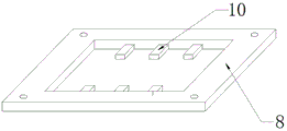
the elastic push plates are arranged in a plurality of numbers, the elastic push plates are fixed on the inner walls of the front side and the rear side of the lifting frame in an equal amount and at equal intervals, and the other sides of the elastic push plates are respectively abutted against the die holders;
the four guide rods are respectively fixed on the four corners of the upper surface of the support table, and the upper ends of the guide rods are movably inserted in the four corners of the lifting frame;
the number of the limiting plates is four, and one of the limiting plates is correspondingly sleeved and fixed on the middle end of the guide rod;
the four reset springs are correspondingly sleeved on the guide rod, and the upper end and the lower end of each reset spring are respectively fixedly connected with the lifting frame and the limiting plate;
the cleaning mechanism is arranged above the supporting table and below the lifting frame, and discharge ports are formed in two side walls of the supporting table;
the two collecting boxes are respectively arranged on the outer sides of the supporting legs, and the collecting boxes are arranged below the discharge port;
the two support plates are respectively arranged in the left side and the right side of the base, and the upper side wall of the support plate positioned outside the base is abutted against the lower side wall of the collecting box;
and the material guide mechanism is arranged in the support table.
Preferably, the cleaning mechanism comprises:
the two side plates are respectively fixed on the left side and the right side of the upper surface of the support platform;
the stirring reciprocating screw rod is suspended above the supporting table, two ends of the stirring reciprocating screw rod are respectively connected with the side plates on two sides in a rotating mode through bearings, and the middle end of the stirring reciprocating screw rod is arranged between a vertical plate of the fixing frame and a vertical plate of the supporting frame;
the lower side of the scraper is in contact with the upper surface of the support table, and the center of the upper side wall of the scraper is fixedly connected with a nut which is used for shifting the reciprocating screw rod;
the two guide posts are respectively arranged on the front side and the rear side of the toggle reciprocating screw rod, two ends of each guide post are respectively fixedly connected with the side plates on the two sides, and a linear bearing on each guide post is fixedly connected with the front side and the rear side of the lower side wall of the scraper;
the driving motor is fixed on the right side wall of the side plate on the right side and connected with an external power supply, and an output shaft of the driving motor is inserted into the side plate on the right side and fixedly connected with the right end of the reciprocating screw rod.
Preferably, a reinforcing plate is fixed on each of the side walls of the supporting legs far away from the center of the base, the lower side wall of the reinforcing plate is fixed on the upper surface of the base, and when the supporting legs support the supporting platform, the supporting legs are further supported through the reinforcing plate.
Preferably, the support plate is adjacent to one side wall of the base and is fixed with an inserting plate, the inserting plate is inserted into the base and fixed through a bolt, when the collecting box is supported through the support plate, the support plate is moved, so that the inserting plate moves in the base until the collecting box reaches a proper position, and then the bolt is screwed down, thereby being applicable to collecting boxes with different sizes.
Preferably, the material guiding mechanism comprises:
the fixing plate is arranged in a U shape and is suspended above the base, and vertical plates on two sides of the fixing plate are fixedly connected with the supporting legs on the front side and the rear side respectively;
the rotating motor is fixed on the lower surface of the transverse plate of the fixing plate and is connected with an external power supply, and an output shaft of the rotating motor passes through the transverse plate of the fixing plate and is suspended in the fixing plate;
the driving bevel gear is suspended inside the fixing plate and sleeved and fixed on an output shaft of the rotating motor;
the driven bevel gear is arranged below the supporting platform and is meshed with the driving bevel gear;
two driving reciprocating screw rods are arranged, the two driving reciprocating screw rods are respectively fixed on two side walls of the driven bevel gear, and the other ends of the driving reciprocating screw rods are respectively connected with vertical plates on two sides of the fixed plate in a screwing manner through bearings;
the two pushing rods are arranged, one ends of the two pushing rods are fixed on the outer ring wall of a nut on the driving reciprocating screw rod, and the other ends of the two pushing rods penetrate through vertical plates on two sides of the fixing plate respectively and then are exposed to the outer side of the fixing plate;
the guide plates are two, the two guide plates are respectively suspended on two sides of the supporting table, the upper sides of the guide plates are connected with the supporting table through hinged seats, a connecting piece is arranged in a sliding groove in the side wall of the guide plate adjacent to the push rod in a sliding mode, and the connecting piece is connected with the push rod through bolts.
Preferably, the stock guide in all insert and be equipped with the extension plate, the downside of this extension plate passes behind the downside of stock guide, contradict on the last lateral wall of collecting box, the equidistance is fixed with the several spring of contradicting on the inner wall of stock guide upside, the lower extreme equidistance of this spring of contradicting is fixed on the inner wall of extension plate, when leading to the waste material of following discharge gate discharge, drive the stock guide through the catch bar and rotate, and then drive the extension plate and remove, the extension plate is at the in-process that removes, the spring of contradicting promotes the extension plate, the distance of extension direction.
The working principle of the invention is as follows: when in use, the two fixing frames are respectively moved to proper positions according to the size of the stamping raw material, the proper die holder is arranged on the fixing frames, the raw material is placed on the die holder, the cylinder drives the stamping die to press downwards, the raw material is processed by the matching of the stamping die and the die holder, the lifting frame is driven to move downwards in the processing process, so that the reset spring is compressed, after the processing is finished, the cylinder drives the stamping die to move upwards, the lifting frame moves upwards under the elasticity of the reset spring, further driving the processed sheet metal part to move upwards, the waste material falls onto the workbench, starting the cleaning mechanism, pushing the waste material into the discharge port by the cleaning mechanism, and then falling into the collection box through the discharge port, accomodate through the collecting box, meanwhile, start guide mechanism, guide mechanism leads the waste material for the waste material is even falls to the collecting box in.
Compared with the prior art, the invention has the beneficial effects that:
1. the outer side of the die holder is provided with a lifting frame, the inner wall of the lifting frame is provided with an elastic push plate, and the elastic push plate can push the formed material upwards, so that the material is conveniently discharged;
2. the die holder is fixed on the upper side of the fixing frame, so that materials are suspended above the supporting table, after the materials are subjected to punch forming, the materials are conveniently separated from the waste materials, the waste materials fall onto the supporting table, the waste materials are cleaned through the cleaning mechanism, the cleaned waste materials are discharged into the collecting box through the discharge port, and the waste materials are conveniently cleaned;
3. the downside of brace table is equipped with guide mechanism, and guide mechanism can fall the even distribution of waste material to the collecting box in, and then has avoided the waste material to pile up one side in the collecting box, causes the waste material to drop.
Drawings
FIG. 1 is a schematic structural diagram of the present invention.
Fig. 2 is an enlarged view of a portion a in fig. 1.
Fig. 3 is an enlarged view of a portion B in fig. 1.
Fig. 4 is a schematic structural view of the lifting frame of the present invention.
Fig. 5 is a schematic structural view of a material guide plate and an elongated plate according to the present invention.
Description of reference numerals:
the device comprises a supporting table 1, supporting legs 2, a base 3, a supporting frame 4, an air cylinder 5, a stamping die 6, a die holder 7, a lifting frame 8, a fixed frame 9, an elastic push plate 10, a guide rod 11, a limiting plate 12, a return spring 13, a cleaning mechanism 14, a side plate 14-1, a toggle reciprocating screw rod 14-2, a scraping plate 14-3, a guide column 14-4, a driving motor 14-5, a discharge port 15, a collecting box 16, a supporting plate 17, a material guide mechanism 18, a fixing plate 18-1, a rotating motor 18-2, a driving bevel gear 18-3, a driven bevel gear 18-4, a driving reciprocating screw rod 18-5, a pushing rod 18-6, a material guide plate 18-7, a connecting piece 18-8, a reinforcing plate 19, a flashboard 20, an extension plate 21 and a collision spring 22.
Detailed Description
The technical solutions in the embodiments of the present invention will be clearly and completely described below with reference to the drawings in the embodiments of the present invention, and it is obvious that the described embodiments are only a part of the embodiments of the present invention, and not all of the embodiments. All other embodiments, which can be derived by a person skilled in the art from the embodiments given herein without making any creative effort, shall fall within the protection scope of the present invention.
As shown in fig. 1 to 5, the following technical solutions are adopted in the present embodiment: the stamping die comprises a supporting table 1, supporting legs 2, a base 3, a supporting frame 4, a cylinder 5, a stamping die 6 and a die holder 7, wherein the supporting legs 2 are fixedly welded at four corners of the upper surface of the base 3, the upper ends of the supporting legs 2 are fixedly welded on the lower surface of the supporting table 1, the supporting frame 4 is arranged at the upper side of the supporting table 1, the supporting frame 4 is arranged in an inverted L shape, a vertical plate of the supporting frame 4 is fixedly welded with the rear side of the upper surface of the supporting table 1, the cylinder 5 is fixedly arranged on the upper side wall of a transverse plate of the supporting frame 4 through a bolt, the cylinder 5 is connected with an external air source, a piston rod of the cylinder 5 penetrates through the transverse plate of the supporting frame 4 and is fixedly connected with the stamping die 6 through a bolt, the die holder 7 is arranged at the lower side of the stamping die 6, and the die holder 7 is arranged at the upper side of the supporting table 1; it also includes:
the lifting frame 8 is arranged above the supporting platform 1 in a hanging mode, and the die holder 7 is arranged in the lifting frame 8 in a hanging mode;
the two fixing frames 9 are arranged in a Z shape, the rear side of the transverse plate on the upper side of the fixing frame 9 is arranged in a sliding groove on the front side wall of the vertical plate of the support frame 4 in a sliding manner, the transverse plate on the lower side of the fixing frame 9 is connected with the upper side wall of the support table 1 through bolts, and the die holder 7 is fixed on the transverse plate of the fixing frame 9 through bolts;
the elastic push plates 10 are provided in a plurality, the elastic push plates 10 are welded and fixed on the inner walls of the front side and the rear side of the lifting frame 8 in an equal amount and at equal intervals, and the other sides of the elastic push plates 10 are respectively abutted against the die holders 7;
the number of the guide rods 11 is four, the four guide rods 11 are respectively welded and fixed on four corners of the upper surface of the support table 1, and the upper ends of the guide rods 11 are movably inserted in the four corners of the lifting frame 8;
the number of the limiting plates 12 is four, and one of the limiting plates 12 is correspondingly sleeved and welded and fixed on the middle end of the guide rod 11;
four return springs 13, wherein one of the four return springs 13 is correspondingly sleeved on the guide rod 11, and the upper end and the lower end of each return spring 13 are respectively welded and fixed with the lifting frame 8 and the limiting plate 12;
the cleaning mechanism 14 is arranged above the supporting table 1, the cleaning mechanism 14 is arranged below the lifting frame 8, and discharge holes 15 are formed in two side walls of the supporting table 1;
the number of the collecting boxes 16 is two, the collecting boxes 16 are respectively arranged on the outer sides of the supporting legs 2, and the collecting boxes 16 are arranged below the discharge port 15;
the number of the supporting plates 17 is two, the two supporting plates 17 are respectively arranged in the left side and the right side of the base 3, and the upper side wall of the supporting plate 17, which is positioned outside the base 3, is abutted against the lower side wall of the collecting box 16;
and the material guide mechanism 18, wherein the material guide mechanism 18 is arranged in the support table 1.
Preferably, the cleaning mechanism 14 further includes:
the number of the side plates 14-1 is two, and the two side plates 14-1 are respectively welded and fixed on the left side and the right side of the upper surface of the support table 1;
the toggle reciprocating screw rod 14-2 is suspended above the support platform 1, two ends of the toggle reciprocating screw rod 14-2 are respectively screwed with the side plates 14-1 at two sides through bearings, and the middle end of the toggle reciprocating screw rod 14-2 is arranged between a vertical plate of the fixed frame 9 and a vertical plate of the support frame 4;
the lower side of the scraper 14-3 is in contact with the upper surface of the support table 1, and the center of the upper side wall of the scraper 14-3 is riveted and fixed with a nut which is used for shifting the reciprocating screw rod 14-2;
two guide posts 14-4, wherein the number of the guide posts 14-4 is two, the two guide posts 14-4 are respectively arranged at the front side and the rear side of the toggle reciprocating screw rod 14-2, two ends of the guide post 14-4 are respectively riveted and fixed with the side plates 14-1 at the two sides, and a linear bearing on the guide post 14-4 is riveted and fixed with the front side and the rear side of the lower side wall of the scraper 14-3;
the driving motor 14-5 is fixed on the right side wall of the right side plate 14-1 through a bolt, the driving motor 14-5 is connected with an external power supply, and an output shaft of the driving motor 14-5 is inserted into the right side plate 14-1 and is fixedly riveted with the right end of the toggle reciprocating screw rod 14-2.
Preferably, a reinforcing plate 19 is welded and fixed to each of the side walls of the support legs 2 away from the center of the base 3, the lower side wall of the reinforcing plate 19 is welded and fixed to the upper surface of the base 3, and when the support legs 2 support the support table 1, the support legs 2 are further supported by the reinforcing plate 19.
Preferably, the support plate 17 is welded and fixed with an insert plate 20 on a side wall adjacent to the base 3, the insert plates 20 are respectively inserted into the base 3 and fixed by bolts, when the collecting box 16 is supported by the support plate 17, the support plate 17 is moved to move the insert plate 20 in the base 3 until reaching a proper position, and then the bolts are tightened, so that the collecting box 16 is suitable for collecting boxes 16 with different sizes.
Preferably, the material guiding mechanism 18 further includes:
the fixing plate 18-1 is arranged in a U shape, the fixing plate 18-1 is suspended above the base 3, and vertical plates on two sides of the fixing plate 18-1 are riveted and fixed with the supporting legs 2 on the front side and the rear side respectively;
the rotating motor 18-2 is fixed on the lower surface of the transverse plate of the fixing plate 18-1 through bolts, the rotating motor 18-2 is connected with an external power supply, and an output shaft of the rotating motor 18-2 penetrates through the transverse plate of the fixing plate 18-1 and then is suspended in the fixing plate 18-1;
the driving bevel gear 18-3 is suspended inside the fixed plate 18-1, and the driving bevel gear 18-3 is sleeved and riveted on an output shaft of the rotating motor 18-2;
the driven bevel gear 18-4 is arranged below the supporting platform 1, and the driven bevel gear 18-4 is meshed with the driving bevel gear 18-3;
two driving reciprocating screw rods 18-5 are provided, the two driving reciprocating screw rods 18-5 are respectively riveted and fixed on two side walls of the driven bevel gear 18-4, and the other ends of the driving reciprocating screw rods 18-5 are respectively screwed with vertical plates on two sides of the fixed plate 18-1 through bearings;
two push rods 18-6 are provided, one end of each of the two push rods 18-6 is riveted and fixed on the outer ring wall of a nut on the driving reciprocating screw rod 18-5, and the other end of each of the two push rods 18-6 is exposed outside the fixed plate 18-1 after penetrating through vertical plates on two sides of the fixed plate 18-1;
the device comprises two material guide plates 18-7, the two material guide plates 18-7 are respectively suspended at two sides of the support platform 1, the upper sides of the material guide plates 18-7 are screwed with the support platform 1 through hinged seats, a connecting piece 18-8 is arranged in a sliding groove in the side wall of the material guide plate 18-7 adjacent to the push rod 18-6 in a sliding mode, and the connecting piece 18-8 is screwed with the push rod 18-6 through bolts.
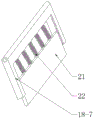
Preferably, an elongated plate 21 is inserted into each of the material guiding plates 18-7, a lower side of the elongated plate 21 penetrates through a lower side of the material guiding plate 18-7 and abuts against an upper side wall of the collecting box 16, a plurality of abutting springs 22 are riveted and fixed on an inner wall of an upper side of the material guiding plate 18-7 at equal intervals, lower ends of the abutting springs 22 are riveted and fixed on an inner wall of the elongated plate 21 at equal intervals, when guiding the waste material discharged from the discharge hole 15, the material guiding plate 18-7 is driven to rotate by the push rod 18-6, the elongated plate 21 is driven to move, and in the moving process of the elongated plate 21, the abutting springs 22 push the elongated plate 21 to lengthen the guiding distance
The working principle of the specific embodiment is as follows: when the stamping die is used, two fixing frames 9 are respectively moved to appropriate positions according to the size of a stamping raw material, an appropriate die holder 7 is installed on the fixing frames 9, the raw material is placed on the die holder 7, the stamping die 6 is driven by the air cylinder 5 to apply pressure downwards, the raw material is processed by matching the stamping die 6 with the die holder 7, the lifting frame 8 is driven to move downwards in the processing process, the reset spring 13 is compressed, after the processing is finished, the stamping die 6 is driven by the air cylinder 5 to move upwards, the lifting frame 8 moves upwards under the elastic force of the reset spring 13, the processed sheet metal part is further driven to move upwards, the waste material falls onto a working table, the cleaning mechanism 14 is started, the waste material is pushed into the discharge port 15 by the cleaning mechanism 14 and then falls into the collecting box 16 through the discharge port 15 and is stored by the collecting box 16, meanwhile, the guide mechanism 18 is started, and guides the waste material by the guide mechanism 18, allowing the waste material to fall evenly into the collection bin 16.
Compared with the prior art, the beneficial effects of the embodiment are as follows:
1. a lifting frame 8 is arranged on the outer side of the die holder 7, an elastic push plate 10 is arranged on the inner wall of the lifting frame 8, and the elastic push plate 10 can push the formed material upwards, so that the material is conveniently discharged;
2. the die holder 7 is fixed on the upper side of the fixing frame 9, so that materials are suspended above the supporting table 1, after the materials are subjected to punch forming, the materials are conveniently separated from waste materials, the waste materials fall onto the supporting table 1, the waste materials are cleaned through the cleaning mechanism 14, the cleaned waste materials are discharged into the collecting box 16 through the discharge port 15, and the waste materials are conveniently cleaned;
3. the lower side of the supporting table 1 is provided with a material guiding mechanism 18, the material guiding mechanism 18 can uniformly distribute the waste materials into the collecting box 16, and the waste materials are prevented from being accumulated on one side in the collecting box 16 to cause the waste materials to drop.
Although the present invention has been described in detail with reference to the foregoing embodiments, it will be apparent to those skilled in the art that various changes in the embodiments and/or modifications of the invention can be made, and equivalents and modifications of some features of the invention can be made without departing from the spirit and scope of the invention.
Claims (7)
1. A stamping device for sheet metal part processing convenient for waste cleaning comprises a supporting table (1), supporting legs (2), a base (3), a supporting frame (4), a cylinder (5), a stamping die (6) and a die holder (7), wherein the supporting legs (2) are fixed at four corners of the upper surface of the base (3), the upper ends of the supporting legs (2) are fixed on the lower surface of the supporting table (1), the supporting frame (4) is arranged at the upper side of the supporting table (1), the supporting frame (4) is arranged in an inverted L shape, a vertical plate of the supporting frame (4) is fixedly connected with the rear side of the upper surface of the supporting table (1), the cylinder (5) is fixed on the upper side wall of a transverse plate of the supporting frame (4), the cylinder (5) is connected with an external air source, a piston rod of the cylinder (5) penetrates through the transverse plate of the supporting frame (4) and is fixedly connected with the stamping die (6), the die holder (7) is arranged at the lower side of the stamping die holder (6), the die holder (7) is arranged on the upper side of the support table (1); it is characterized in that it also comprises:
the lifting frame (8) is arranged above the supporting platform (1) in a hanging manner, and the die holder (7) is arranged in the lifting frame (8) in a hanging manner;
the device comprises two fixing frames (9), wherein the two fixing frames (9) are arranged in a Z shape, the rear side of a transverse plate on the upper side of each fixing frame (9) is arranged in a sliding groove in the front side wall of a vertical plate of the support frame (4) in a sliding manner, the transverse plate on the lower side of each fixing frame (9) is connected with the upper side wall of the support table (1) through bolts, and the die holder (7) is fixed on the transverse plate of each fixing frame (9);
the lifting frame is characterized by comprising a plurality of elastic push plates (10), wherein the elastic push plates (10) are a plurality, the elastic push plates (10) are fixed on the inner walls of the front side and the rear side of the lifting frame (8) in an equal amount and at equal intervals, and the other sides of the elastic push plates (10) are respectively abutted against the die holders (7);
the four guide rods (11) are respectively fixed on the four corners of the upper surface of the support table (1), and the upper ends of the guide rods (11) are movably inserted in the four corners of the lifting frame (8);
the number of the limiting plates (12) is four, and one of the four limiting plates (12) is correspondingly sleeved and fixed on the middle end of the guide rod (11);
the four return springs (13) are correspondingly sleeved on the guide rod (11), and the upper end and the lower end of each return spring (13) are respectively fixedly connected with the lifting frame (8) and the limiting plate (12);
the cleaning mechanism (14) is arranged above the supporting platform (1), the cleaning mechanism (14) is arranged below the lifting frame (8), and discharge holes (15) are formed in two side walls of the supporting platform (1);
the number of the collecting boxes (16) is two, the collecting boxes (16) are respectively arranged on the outer sides of the supporting legs (2), and the collecting boxes (16) are arranged below the discharge port (15);
the two supporting plates (17) are arranged, the two supporting plates (17) are respectively arranged in the left side and the right side of the base (3), and the upper side wall, positioned outside the base (3), of the supporting plates (17) is abutted against the lower side wall of the collecting box (16);
the material guide mechanism (18), the material guide mechanism (18) set up in the brace table (1).
2. The stamping device for sheet metal part machining convenient to clearance waste of claim 1, characterized in that: the cleaning mechanism (14) comprises:
the two side plates (14-1) are arranged, and the two side plates (14-1) are respectively fixed on the left side and the right side of the upper surface of the support table (1);
the stirring reciprocating screw rod (14-2), the stirring reciprocating screw rod (14-2) is suspended above the support platform (1), two ends of the stirring reciprocating screw rod (14-2) are respectively connected with the side plates (14-1) at two sides in a rotating mode through bearings, and the middle end of the stirring reciprocating screw rod (14-2) is arranged between the vertical plate of the fixing frame (9) and the vertical plate of the support frame (4);
the lower side of the scraper (14-3) is in contact with the upper surface of the support table (1), and the center of the upper side wall of the scraper (14-3) is fixedly connected with a nut on the toggle reciprocating screw rod (14-2);
the number of the guide columns (14-4) is two, the two guide columns (14-4) are respectively arranged on the front side and the rear side of the toggle reciprocating screw rod (14-2), two ends of each guide column (14-4) are respectively fixedly connected with the side plates (14-1) on the two sides, and linear bearings on the guide columns (14-4) are fixedly connected with the front side and the rear side of the lower side wall of the scraper (14-3);
the driving motor (14-5) is fixed on the right side wall of the right side plate (14-1), the driving motor (14-5) is connected with an external power supply, and an output shaft of the driving motor (14-5) is inserted into the right side plate (14-1) and is fixedly connected with the right end of the toggle reciprocating screw rod (14-2).
3. The stamping device for sheet metal part machining convenient to clearance waste of claim 1, characterized in that: a reinforcing plate (19) is fixed on one side wall of the supporting leg (2) far away from the center of the base (3), the lower side wall of the reinforcing plate (19) is fixed on the upper surface of the base (3), and when the supporting leg (2) supports the supporting platform (1), the supporting leg (2) is further supported through the reinforcing plate (19).
4. The stamping device for sheet metal part machining convenient to clearance waste of claim 1, characterized in that: backup pad (17) all be fixed with picture peg (20) on being adjacent to a lateral wall of base (3), this picture peg (20) are inserted respectively and are established in base (3), and through the bolt fastening, when supporting collecting box (16) through backup pad (17), remove backup pad (17) for picture peg (20) remove in base (3), until reaching suitable position, screw up the bolt again, thereby be applicable to not collecting box (16) of equidimension.
5. The stamping device for sheet metal part machining convenient to clearance waste of claim 1, characterized in that: the material guiding mechanism (18) comprises:
the fixing plate (18-1) is arranged in a U shape, the fixing plate (18-1) is suspended above the base (3), and vertical plates on two sides of the fixing plate (18-1) are respectively fixedly connected with the supporting legs (2) on the front side and the rear side;
the rotating motor (18-2), the said rotating motor (18-2) is fixed on the lower surface of the horizontal plate of the dead plate (18-1), the rotating motor (18-2) is connected with external power, the output shaft of the rotating motor (18-2) is suspended in dead plate (18-1) after passing through the horizontal plate of the dead plate (18-1);
the driving bevel gear (18-3), the said driving bevel gear (18-3) is hung in the inside of the dead plate (18-1), and the driving bevel gear (18-3) is set up and fixed on output shaft of the rotating electrical machinery (18-2);
the driven bevel gear (18-4), the driven bevel gear (18-4) is arranged below the supporting platform (1), and the driven bevel gear (18-4) is meshed with the driving bevel gear (18-3);
two driving reciprocating screw rods (18-5), wherein the two driving reciprocating screw rods (18-5) are respectively fixed on two side walls of the driven bevel gear (18-4), and the other ends of the driving reciprocating screw rods (18-5) are respectively connected with vertical plates on two sides of the fixed plate (18-1) in a screwing manner through bearings;
two pushing rods (18-6), wherein one ends of the two pushing rods (18-6) are fixed on the outer ring wall of a nut on the driving reciprocating screw rod (18-5), and the other ends of the two pushing rods (18-6) respectively penetrate through vertical plates on two sides of the fixing plate (18-1) and then are exposed outside the fixing plate (18-1);
the device comprises two material guide plates (18-7), the two material guide plates (18-7) are respectively suspended at two sides of the supporting platform (1), the upper sides of the material guide plates (18-7) are connected with the supporting platform (1) in a rotating mode through hinged seats, connecting pieces (18-8) are arranged in sliding grooves in the side walls, adjacent to the push rods (18-6), of the material guide plates (18-7) in a sliding mode, and the connecting pieces (18-8) are connected with the push rods (18-6) in a rotating mode through bolts.
6. The stamping device for sheet metal part machining convenient to clearance waste of claim 5, characterized by: the waste material guide device is characterized in that elongated plates (21) are inserted into the guide plates (18-7), the lower sides of the elongated plates (21) penetrate through the lower sides of the guide plates (18-7) and then abut against the upper side wall of the collecting box (16), a plurality of abutting springs (22) are fixed on the inner wall of the upper side of the guide plates (18-7) at equal intervals, the lower ends of the abutting springs (22) are fixed on the inner wall of the elongated plates (21) at equal intervals, when waste materials discharged from a discharge port (15) are guided, the guide plates (18-7) are driven to rotate through push rods (18-6), the elongated plates (21) are driven to move, and in the moving process of the elongated plates (21), the abutting springs (22) push the elongated plates (21) to lengthen the guiding distance.
7. The working principle of the stamping device for sheet metal part machining convenient for waste cleaning according to claim 1 is characterized in that: when the punching die is used, two fixing frames (9) are respectively moved to proper positions according to the size of a punching raw material, a proper die holder (7) is installed on the fixing frames (9), the raw material is placed on the die holder (7), the punching die (6) is driven to apply pressure downwards through the air cylinder (5), the raw material is processed through the matching of the punching die (6) and the die holder (7), the lifting frame (8) is driven to move downwards in the processing process, so that the reset spring (13) is compressed, after the processing is finished, the air cylinder (5) drives the punching die (6) to move upwards, the lifting frame (8) moves upwards under the elastic force of the reset spring (13), further the processed sheet metal part is driven to move upwards, the waste falls onto the workbench, the cleaning mechanism (14) is started, the cleaning mechanism (14) pushes the waste into the discharge hole (15), and then falls into the collection box (16) through the discharge hole (15), accomodate through collecting box (16), meanwhile, start guide mechanism (18), guide mechanism (18) leads the waste material for the waste material is even to fall in collecting box (16).
Priority Applications (1)
| Application Number | Priority Date | Filing Date | Title |
|---|---|---|---|
| CN202111146945.0A CN113976705B (en) | 2021-09-29 | 2021-09-29 | Stamping device is used in sheet metal component processing convenient to clearance waste material |
Applications Claiming Priority (1)
| Application Number | Priority Date | Filing Date | Title |
|---|---|---|---|
| CN202111146945.0A CN113976705B (en) | 2021-09-29 | 2021-09-29 | Stamping device is used in sheet metal component processing convenient to clearance waste material |
Publications (2)
| Publication Number | Publication Date |
|---|---|
| CN113976705A true CN113976705A (en) | 2022-01-28 |
| CN113976705B CN113976705B (en) | 2023-08-29 |
Family
ID=79737101
Family Applications (1)
| Application Number | Title | Priority Date | Filing Date |
|---|---|---|---|
| CN202111146945.0A Active CN113976705B (en) | 2021-09-29 | 2021-09-29 | Stamping device is used in sheet metal component processing convenient to clearance waste material |
Country Status (1)
| Country | Link |
|---|---|
| CN (1) | CN113976705B (en) |
Cited By (2)
| Publication number | Priority date | Publication date | Assignee | Title |
|---|---|---|---|---|
| CN114733992A (en) * | 2022-04-29 | 2022-07-12 | 靖江市联友模具制造有限公司 | Numerical control processing aluminum product extrusion frock |
| CN115178661A (en) * | 2022-09-13 | 2022-10-14 | 张家港拓普五金制品有限公司 | Punching equipment for machining automobile door hinge |
Citations (3)
| Publication number | Priority date | Publication date | Assignee | Title |
|---|---|---|---|---|
| CN109158381A (en) * | 2018-09-19 | 2019-01-08 | 天津英浩电子有限公司 | A kind of metal plate punching facilitating installation waste material cleaning equipment |
| CN111300017A (en) * | 2020-03-10 | 2020-06-19 | 湖北三峡职业技术学院 | Bearing press-fitting mechanism of automobile steering system |
| JP6753013B1 (en) * | 2019-08-09 | 2020-09-09 | 广州克力労保用品有限公司 | Urban sewerage communication equipment |
-
2021
- 2021-09-29 CN CN202111146945.0A patent/CN113976705B/en active Active
Patent Citations (3)
| Publication number | Priority date | Publication date | Assignee | Title |
|---|---|---|---|---|
| CN109158381A (en) * | 2018-09-19 | 2019-01-08 | 天津英浩电子有限公司 | A kind of metal plate punching facilitating installation waste material cleaning equipment |
| JP6753013B1 (en) * | 2019-08-09 | 2020-09-09 | 广州克力労保用品有限公司 | Urban sewerage communication equipment |
| CN111300017A (en) * | 2020-03-10 | 2020-06-19 | 湖北三峡职业技术学院 | Bearing press-fitting mechanism of automobile steering system |
Non-Patent Citations (1)
| Title |
|---|
| 王仁龙;: "一种编织袋填装后的自动折边缝纫装置", 塑料包装, no. 03 * |
Cited By (2)
| Publication number | Priority date | Publication date | Assignee | Title |
|---|---|---|---|---|
| CN114733992A (en) * | 2022-04-29 | 2022-07-12 | 靖江市联友模具制造有限公司 | Numerical control processing aluminum product extrusion frock |
| CN115178661A (en) * | 2022-09-13 | 2022-10-14 | 张家港拓普五金制品有限公司 | Punching equipment for machining automobile door hinge |
Also Published As
| Publication number | Publication date |
|---|---|
| CN113976705B (en) | 2023-08-29 |
Similar Documents
| Publication | Publication Date | Title |
|---|---|---|
| CN113976705A (en) | Stamping device is used in sheet metal component processing convenient to clearance waste material | |
| CN211413403U (en) | Material collecting device of hole expanding machine | |
| CN211360388U (en) | Full-automatic stamping production line | |
| CN109454925B (en) | Perforating device is used in corrugated paper processing | |
| CN111438262B (en) | Automatic cutting machine | |
| CN216501847U (en) | Compact type punching processing die | |
| CN214640635U (en) | Steel plate shearing machine | |
| CN214108430U (en) | Automatic hardware stamping device of ejection of compact | |
| CN212264312U (en) | Continuous stamping die for automobile shock absorption sheet | |
| CN215391855U (en) | Punch press with slip ejection of compact structure | |
| CN218926422U (en) | Automatic feeding cutting machine | |
| CN220127438U (en) | Punching machine material feeding unit | |
| CN220387708U (en) | Stamping die waste material discharging mechanism | |
| CN216801869U (en) | Aluminum plate processing and slitting equipment | |
| CN217531053U (en) | Automatic clear useless device of printing paper cross cutting | |
| CN212310559U (en) | Punching die for machining support | |
| CN220480015U (en) | Stamping die capable of adjusting pushing cleaning structure and automatically feeding and discharging | |
| CN214051842U (en) | Material crushing device for industrial production | |
| CN219378247U (en) | Buffer device for stamping die of automobile body sheet metal part | |
| CN220295724U (en) | Stamping device suitable for stainless steel fork processing | |
| CN219924303U (en) | Inside and outside hole flanging processing die | |
| CN218775473U (en) | Continuous punch forming device for metal piece | |
| CN218517522U (en) | Device for punching holes in front slave plate seat of railway wagon | |
| CN215145271U (en) | Novel cutting is used in mould steel processing device | |
| CN219405542U (en) | Automatic bottle cap molding device |
Legal Events
| Date | Code | Title | Description |
|---|---|---|---|
| PB01 | Publication | ||
| PB01 | Publication | ||
| SE01 | Entry into force of request for substantive examination | ||
| SE01 | Entry into force of request for substantive examination | ||
| GR01 | Patent grant | ||
| GR01 | Patent grant |