CN113957665A - Clothes treatment equipment - Google Patents
Clothes treatment equipment Download PDFInfo
- Publication number
- CN113957665A CN113957665A CN202111256025.4A CN202111256025A CN113957665A CN 113957665 A CN113957665 A CN 113957665A CN 202111256025 A CN202111256025 A CN 202111256025A CN 113957665 A CN113957665 A CN 113957665A
- Authority
- CN
- China
- Prior art keywords
- height
- main body
- operation circuit
- machine operation
- equipment main
- Prior art date
- Legal status (The legal status is an assumption and is not a legal conclusion. Google has not performed a legal analysis and makes no representation as to the accuracy of the status listed.)
- Pending
Links
- 238000001514 detection method Methods 0.000 claims abstract description 35
- 230000007246 mechanism Effects 0.000 claims abstract description 21
- 238000006073 displacement reaction Methods 0.000 claims abstract description 17
- 230000013011 mating Effects 0.000 claims description 16
- 238000005406 washing Methods 0.000 claims description 6
- 125000006850 spacer group Chemical group 0.000 claims 2
- 238000001035 drying Methods 0.000 claims 1
- 238000010276 construction Methods 0.000 description 5
- 238000009434 installation Methods 0.000 description 3
- 238000000034 method Methods 0.000 description 3
- 230000008569 process Effects 0.000 description 3
- 230000008859 change Effects 0.000 description 2
- 230000001960 triggered effect Effects 0.000 description 2
- 241001391944 Commicarpus scandens Species 0.000 description 1
- 230000006978 adaptation Effects 0.000 description 1
- 238000005452 bending Methods 0.000 description 1
- 230000009286 beneficial effect Effects 0.000 description 1
- 239000004020 conductor Substances 0.000 description 1
- 238000010586 diagram Methods 0.000 description 1
- 230000006872 improvement Effects 0.000 description 1
- 230000004048 modification Effects 0.000 description 1
- 238000012986 modification Methods 0.000 description 1
- 238000006467 substitution reaction Methods 0.000 description 1
Images


Classifications
-
- D—TEXTILES; PAPER
- D06—TREATMENT OF TEXTILES OR THE LIKE; LAUNDERING; FLEXIBLE MATERIALS NOT OTHERWISE PROVIDED FOR
- D06F—LAUNDERING, DRYING, IRONING, PRESSING OR FOLDING TEXTILE ARTICLES
- D06F34/00—Details of control systems for washing machines, washer-dryers or laundry dryers
- D06F34/14—Arrangements for detecting or measuring specific parameters
-
- D—TEXTILES; PAPER
- D06—TREATMENT OF TEXTILES OR THE LIKE; LAUNDERING; FLEXIBLE MATERIALS NOT OTHERWISE PROVIDED FOR
- D06F—LAUNDERING, DRYING, IRONING, PRESSING OR FOLDING TEXTILE ARTICLES
- D06F34/00—Details of control systems for washing machines, washer-dryers or laundry dryers
- D06F34/08—Control circuits or arrangements thereof
-
- D—TEXTILES; PAPER
- D06—TREATMENT OF TEXTILES OR THE LIKE; LAUNDERING; FLEXIBLE MATERIALS NOT OTHERWISE PROVIDED FOR
- D06F—LAUNDERING, DRYING, IRONING, PRESSING OR FOLDING TEXTILE ARTICLES
- D06F2105/00—Systems or parameters controlled or affected by the control systems of washing machines, washer-dryers or laundry dryers
- D06F2105/62—Stopping or disabling machine operation
Landscapes
- Engineering & Computer Science (AREA)
- Textile Engineering (AREA)
- Main Body Construction Of Washing Machines And Laundry Dryers (AREA)
Abstract
The invention belongs to the technical field of clothes treatment and discloses a clothes treatment device. The clothes treatment equipment comprises an equipment main body and a displacement detection mechanism, wherein a complete machine operation circuit is arranged in the equipment main body; the displacement detection mechanism is electrically connected with the complete machine operation circuit, and can disconnect the complete machine operation circuit after detecting the displacement of the equipment main body. This clothing treatment facility can in time detect whether the equipment main part takes place to remove, and can switch complete machine operation circuit after detecting the equipment main part and remove, makes the equipment main part stop the operation to avoid the equipment main part to collide with and damage or harm user personal safety.
Description
Technical Field
The invention relates to the technical field of clothes treatment, in particular to clothes treatment equipment.
Background
Dryers and washers are common laundry treating apparatuses. In the working process of the clothes dryer and the washing machine, because the drum rotates at a high speed, if clothes are placed unevenly, the whole machine is easy to shift, so that the whole machine is easy to collide with surrounding objects, the noise is high, and the machine is easy to break down. Especially when the clothes dryer and the washing machine are stacked up and down, if the equipment above the clothes dryer and the washing machine is displaced, the problems of unstable placement and even falling are easily caused, and personal safety is affected.
Therefore, there is a high necessity for a laundry treating apparatus to solve the above problems.
Disclosure of Invention
The invention aims to provide a clothes treatment device to solve the potential safety hazard after the device is displaced due to vibration and the like.
In order to achieve the purpose, the invention adopts the following technical scheme:
a laundry treating apparatus, comprising:
the equipment comprises an equipment main body, wherein a complete machine operation circuit is arranged in the equipment main body;
the displacement detection mechanism is electrically connected with the complete machine operation circuit and can disconnect the complete machine operation circuit after detecting that the equipment main body is displaced.
As an alternative to the above laundry treating apparatus, the displacement detecting mechanism includes:
the height difference construction structure is arranged on a bearing surface for bearing the equipment main body, one of the height difference construction structure and the bearing surface is provided with a first height matching surface, the other one of the height difference construction structure and the bearing surface is provided with a second height matching surface, and the first height matching surface is higher than the second height matching surface;
a detection component disposed at a bottom of the device body, the detection component configured to turn on the complete machine operation circuit when aligned with the first height mating face and turn off the complete machine operation circuit when aligned with the second height mating face.
As an alternative to the above laundry treating apparatus, the detecting unit includes:
the limit switch is connected in series in the whole machine operation circuit;
the trigger rod is connected to the equipment main body in a sliding mode along the vertical direction, and when the bottom end of the trigger rod is abutted to the first height matching surface, the top of the trigger rod triggers the limit switch so that the limit switch is closed;
the elastic piece can drive the trigger rod to move downwards so that the top of the trigger rod is separated from the limit switch.
As an alternative to the above laundry treating apparatus, the apparatus main body includes:
the detection assembly is arranged on the bottom surface of the box body;
the supporting legs are arranged on the bottom surface of the box body and supported on the bearing surface.
As an alternative to the above laundry treating apparatus, the height difference constructing structure is a pad, a top surface of the pad is a first height fitting surface, and the supporting surface is configured with the second height fitting surface.
As an alternative of the above clothes treatment apparatus, the pad block has a circular truncated cone structure or a truncated pyramid structure, and the area of the top surface of the pad block is smaller than the area of the bottom surface of the pad block.
As an alternative of the above clothes treating apparatus, the height difference constructing structure is a groove provided on the supporting surface, a bottom surface of the groove is the second height fitting surface, and the supporting surface is configured with the first height fitting surface.
As an alternative to the above laundry treating apparatus, the recess is an annular groove, and the bearing surface located in the recess is the first height mating surface.
As an alternative to the above-described clothes treating apparatus, the number of the apparatus main bodies is set to two, two of the apparatus main bodies are stacked one on top of the other, and at least the upper one of the apparatus main bodies is provided with the displacement detecting mechanism.
As an alternative to the above laundry treating apparatus, the apparatus main body is a washing machine or a dryer.
The invention has the beneficial effects that:
the clothes treatment equipment provided by the invention can timely detect whether the equipment main body moves or not, and can switch the whole machine operation circuit after detecting that the equipment main body moves, so that the equipment main body stops operating, and the equipment main body is prevented from being collided and damaged or the personal safety of a user is prevented from being damaged.
Drawings
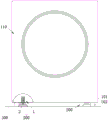
FIG. 1 is a schematic view illustrating a structure of a clothes treating apparatus according to the present invention when placed on a supporting surface;
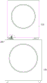
FIG. 2 is a schematic structural view of another laundry treating apparatus according to the present invention;
fig. 3 is an exploded view of another laundry treating apparatus provided in the present invention;
FIG. 4 is a schematic structural view of a displacement sensing mechanism provided in the present invention;
FIG. 5 is a top view of a second body provided by the present invention;
FIG. 6 is a bottom view of the first body provided by the present invention;
fig. 7 is a schematic diagram of a detection mechanism and a complete machine operation circuit provided by the invention.
In the figure:
110. a first body; 101. a box body; 102. supporting legs; 120. a second body; 200. a displacement detection mechanism; 1. a limit switch; 11. a housing; 111. an annular side plate; 112. a base plate; 113. a fastener; 114. a top plate; 1141. a guide post; 12. a normally open contact; 13. a trigger lever; 131. a rod portion; 132. a limiting part; 2. cushion blocks; 21. a first height mating surface; 300. a bearing surface; 400. the whole machine runs a circuit.
Detailed Description
The present invention will be described in further detail with reference to the accompanying drawings and examples. It is to be understood that the specific embodiments described herein are merely illustrative of the invention and are not limiting of the invention. It should be further noted that, for the convenience of description, only some of the structures related to the present invention are shown in the drawings, not all of the structures.
In the description of the present invention, unless expressly stated or limited otherwise, the terms "connected," "connected," and "fixed" are to be construed broadly, e.g., as meaning permanently connected, removably connected, or integral to one another; can be mechanically or electrically connected; either directly or indirectly through intervening media, either internally or in any other relationship. The specific meanings of the above terms in the present invention can be understood in specific cases to those skilled in the art.
In the present invention, unless otherwise expressly stated or limited, "above" or "below" a first feature means that the first and second features are in direct contact, or that the first and second features are not in direct contact but are in contact with each other via another feature therebetween. Also, the first feature being "on," "above" and "over" the second feature includes the first feature being directly on and obliquely above the second feature, or merely indicating that the first feature is at a higher level than the second feature. A first feature being "under," "below," and "beneath" a second feature includes the first feature being directly under and obliquely below the second feature, or simply meaning that the first feature is at a lesser elevation than the second feature.
In the description of the present embodiment, the terms "upper", "lower", "right", etc. are used in an orientation or positional relationship based on that shown in the drawings only for convenience of description and simplicity of operation, and do not indicate or imply that the device or element referred to must have a particular orientation, be constructed and operated in a particular orientation, and thus, should not be construed as limiting the present invention. Furthermore, the terms "first" and "second" are used only for descriptive purposes and are not intended to have a special meaning.
The present embodiment provides a laundry treating apparatus, as shown in fig. 1, the laundry treating apparatus includes an apparatus main body including a cabinet 101, an outer tub disposed in the cabinet 101, an inner tub rotatably disposed in the outer tub, a driving mechanism for driving the inner tub to rotate, and a whole machine operating circuit 400. The whole machine operating circuit 400 is electrically connected with the driving mechanism and used for supplying power to the driving mechanism and controlling the driving mechanism to start and stop. Wherein, the apparatus body may be a dryer or a washing machine.
Because the rotating speed of the inner drum in the rotating process is higher, when the clothes in the inner drum are unevenly distributed and the like, the equipment main body vibrates. When the vibration of the equipment main body is large, the clothes treatment equipment is easy to move, the noise of the clothes treatment equipment is increased, the problem that the equipment main body is collided and damaged exists, and potential safety hazards exist.
To solve the above problem, the laundry treating apparatus further includes a displacement detecting mechanism 200. The displacement detection mechanism 200 is electrically connected with the whole machine operation circuit 400, can detect whether the equipment main body is displaced, and can disconnect the whole machine operation circuit 400 after detecting that the equipment main body is displaced, so that the equipment main body stops operating, thereby avoiding the equipment main body from colliding and damaging and ensuring the personal safety of a user.
Specifically, the displacement detection mechanism 200 includes a height difference building structure and a detection assembly. The elevation difference building structure is arranged on the holding plane 300 of the holding device body. One of the elevation difference building structure and the support surface 300 is constructed with a first elevation mating surface 21 and the other is constructed with a second elevation mating surface, the first elevation mating surface 21 being higher than the second elevation mating surface. The detection component is arranged at the bottom of the equipment main body, and the detection component is configured to turn on the whole machine operation circuit 400 when being aligned with the first height matching surface 21 and turn off the whole machine operation circuit 400 when being aligned with the second height matching surface.
In this embodiment, the detection component detects whether the device main body is displaced or not by the height change of the mating surface with which it is mated. When the main body of the apparatus is normally placed on the supporting surface 300, the detecting member is opposed to the first height fitting surface 21. At this time, the main body of the apparatus is not moved, the entire apparatus operating circuit 400 is in a conducting state, and the main body of the apparatus can operate normally. When the main body of the device moves due to excessive vibration or other reasons, the detection component is staggered with the first height matching surface 21, and the detection component is opposite to the second height matching surface. The detection assembly can detect the height change of the matching surface matched with the detection assembly, the equipment main body moves at the moment, the whole machine operation circuit 400 is in a disconnected state, the equipment main body stops operating, the equipment main body is prevented from being collided and damaged, and the personal safety of a user is guaranteed.
Alternatively, as shown in fig. 1, both the apparatus body and the height difference building structure may be placed on the indoor floor, i.e., the supporting surface 300 is the indoor floor. Through the cooperation of the detection assembly and the height difference construction structure, the operation of the equipment main body can be stopped after the equipment main body moves, so that potential safety hazards are eliminated.
In order to ensure that a gap exists between the bottom surface of the box body 101 and the bearing surface 300 so as to meet the matching requirement of the detection component and the height difference construction member, the bottom surface of the box body 101 is further provided with supporting legs 102, the supporting legs 102 are supported on the bearing surface 300, and the supporting legs 102 lift the bottom surface of the box body 101 so as to enable the bottom surface of the box body 101 and the bearing surface 300 to be arranged at intervals.
Optionally, the supporting foot 102 is provided in plurality, and the supporting feet 102 are arranged at intervals along the circumferential direction of the box 101 to stably support the box 101.
Alternatively, as shown in fig. 2, the number of the apparatus main bodies may be two, and the two apparatus main bodies are stacked one on another. For convenience of description, the upper apparatus main body is a first body 110, the lower apparatus main body is a second body 120, the housing 101 of the first body 110 is provided with a detecting member, the top surface of the housing 101 of the second body 120 is a supporting surface 300, and the height difference constructing structure is provided on the top surface of the housing 101 of the second body 120. When two device bodies are stacked, the displacement detection mechanism 200 is disposed between the first body 110 and the second body 120, so that the first body 110 can be stopped after the first body 110 moves relative to the second body 120, and the first body 110 is prevented from being placed unstably and even falling off, thereby ensuring the safety of the device and the human body.
In some embodiments, the detection assembly disposed on the bottom surface of the case 101 of the first body 110 is electrically connected to the overall operation circuit 400 in the second body 120. When the detection component detects that the first body 110 moves relative to the second body 120, the first body 110 and the second body 120 stop operating, so that the first body 110 is prevented from falling off due to the operation of the second body 120, and the personal safety of the equipment and the user is further ensured.
In some embodiments, the first body 110 and the second body 120 are each provided with a displacement detection mechanism 200 to detect whether the first body 110 and the second body 120 move, respectively, further ensuring the safety of the laundry treating apparatus.
As shown in fig. 3, the detecting assembly includes a limit opening, a trigger bar 13, and an elastic member. The limit switch 1 is arranged on the box body 101 and is connected in series in the whole machine operation circuit 400, and the limit switch 1 is in a normally open state. The trigger rod 13 is slidably connected to the apparatus main body in the vertical direction, and the bottom end of the trigger rod 13 can extend out of the box 101. An elastic member is connected to the trigger lever 13, and the elastic member applies an elastic force moving downward to the trigger lever 13. When the detection assembly is not subjected to an external force, the trigger rod 13 is subjected to the elastic force of the elastic member, and the bottom end of the trigger rod 13 extends out of the box 101.
When the apparatus main body is not moved, the bottom end of the trigger lever 13 abuts against the first height engagement surface 21. The trigger rod 13 is supported by the abutting force of the first height matching surface 21 to overcome the elastic force of the elastic piece to move upwards, so that the top of the trigger rod 13 triggers the limit switch 1, the limit switch 1 is triggered to be closed, the whole machine operation circuit 400 is conducted, and the equipment main body can normally operate.
When the main body of the device moves to make the trigger bar 13 staggered with the first height matching surface 21 and move to the position above the second height matching surface, because the second height matching surface is lower than the first height matching surface 21, the trigger bar 13 is no longer subjected to upward abutting force, the trigger bar 13 moves downward under the driving of the elastic piece, so that the top end of the trigger bar 13 is separated from the limit switch 1, the limit switch 1 is restored to a normally open state, the whole machine operation circuit 400 is disconnected, and the main body of the device stops operating.
In this embodiment, the height difference structure is a cushion block 2, the cushion block 2 is disposed on the supporting surface 300, the top surface of the cushion block 2 is a first height matching surface 21, and the supporting surface 300 is a second height matching surface. When the equipment main part is normally placed, the trigger rod 13 is located right above the cushion block 2, so that the cushion block 2 can upwards push the trigger rod 13 to close the limit switch 1.
It should be noted here that the size of the first height engagement surface 21 determines how far the device body moves and then the limit switch 1 can be triggered.
To facilitate the installation of the medical treatment apparatus, the main body of the apparatus is first placed at a designated position on the supporting surface 300, and then the height difference building structure is pushed into the space between the bottom surface of the box 101 and the supporting surface 300, so as to reduce the difficulty of assembling and positioning.
In order to facilitate the installation of the cushion block 2, the cushion block 2 can be in a circular truncated cone structure or a prismatic table structure, and the area of the top surface of the cushion block 2 is smaller than that of the bottom surface of the cushion block 2. The truncated cone structure or the truncated pyramid structure has obliquely arranged side faces. When the cushion block 2 is pushed to the installation position, the inclined side surface of the cushion block 2 is contacted with the extended trigger rod 13 before; after the cushion block 2 is pushed, the bottom end of the trigger rod 13 slides on the inclined side surface to push the trigger rod 13 to compress against the elastic force of the elastic member, thereby facilitating the contact of the trigger rod 13 with the top surface of the cushion block 2.
In some embodiments, the height difference structure may be a groove formed on the supporting surface 300, the bottom surface of the groove is a second height matching surface, and the supporting surface 300 is configured with a first height matching surface 21. When the main body of the device moves, the trigger rod 13 moves from the surface of the bearing surface 300 to the groove, so that the limit switch 1 is turned off, and the whole machine operation circuit 400 is turned off.
In order to enable the detection component to detect in time after the main body of the device moves in any direction, the groove may be an annular groove, and the bearing surface 300 located in the groove is a first height matching surface 21. I.e. the part of the support surface 300 enclosed by the annular groove, is the first level engagement surface 21.
As shown in fig. 3 and 4, the limit switch 1 includes a housing 11 and a normally open contact 12 provided on the housing 11. The housing 11 includes a bottom plate 112, an annular side plate 111, and a top plate 114. The bottom surface of the box 101 is provided with a mounting hole, and the housing 11 is inserted into the mounting hole. The trigger rod 13 and the elastic piece are both arranged in the shell 11, a through hole is arranged on the bottom plate 112, and the bottom end of the trigger rod 13 penetrates through the through hole to extend out of the shell 11.
To facilitate the fixing of the housing 11 to the box 101, a bottom plate 112 of the housing 11 extends outside the annular side plate 111, so that the bottom plate 112 can be fixedly connected to the bottom surface of the box 101 by a fastening member 113 such as a screw. The shape and the size of the annular side plate 111 are matched with those of the mounting hole, and the annular side plate 111 penetrates through the mounting hole so that the normally open contact 12 is connected with the whole machine operation circuit 400.
To prevent the trigger lever 13 from being detached from the housing 11, the trigger lever 13 includes a lever portion 131 and a stopper portion 132. The shape and size of the rod part 131 are matched with those of the through hole, and the rod part 131 is arranged in the through hole in a sliding mode. The limiting portion 132 is protruded along the radial direction of the rod portion 131, so that the limiting portion 132 can abut against the inner wall of the bottom plate 112 to prevent the trigger rod 13 from separating from the housing 11.
Further, in order to avoid the jamming of the trigger rod 13 during the sliding process, the top surface of the housing 11 is provided with the guide post 1141, the rod portion 131 is hollow and sleeved outside the guide post 1141, the sliding direction of the rod portion 131 can be ensured to be accurate through the sliding fit between the rod portion 131 and the guide post 1141, and the jamming of the rod portion 131 caused by the deviation of the sliding direction of the rod portion 131 is avoided.
Optionally, the resilient member is a spring. The spring has simple structure and low cost.
Further, in order to avoid the bending of the spring, the spring is sleeved outside the guide post 1141, one end of the spring abuts against or is connected to the inner wall of the top plate 114, and the other end abuts against or is connected to the limiting portion 132. The spring is in a compressed state so as to be able to apply a downward elastic force to the stopper portion 132.
In this embodiment, the two contacts of the normally open contact 12 are located in the housing 11, and the trigger bar 13 is made of a conductive material. When the trigger bar 13 is pushed by the first height matching surface 21 to move upward to a preset height, the limiting portion 132 of the trigger bar 13 contacts with the two contacts and conducts the two contacts, so that the limit switch 1 is closed.
As shown in fig. 5 and 6, in order to detect more accurately whether the apparatus main body moves, at least two blocks 2 may be provided on the holding surface 300, and the at least two blocks 2 may be provided at intervals in the circumferential direction of the apparatus main body. Every cushion 2 all corresponds and is provided with a determine module to realize that the multiposition detects, improve and detect the accuracy.
In this embodiment, two pads 2 are disposed on the supporting surface 300, and the two pads 2 are disposed along opposite corners of the main body of the apparatus. Correspondingly, the two detection components are also arranged along the opposite corners of the device body.
Further, as shown in fig. 7, the limit switch 1 in each detection assembly corresponding to the same device main body is connected in series in the complete machine operation circuit 400, so that the complete machine operation circuit 400 is disconnected after any detection assembly detects that the device main body moves, thereby eliminating potential safety hazards.
It should be understood that the above-described embodiments of the present invention are merely examples for clearly illustrating the present invention, and are not intended to limit the embodiments of the present invention. Numerous obvious variations, adaptations and substitutions will occur to those skilled in the art without departing from the scope of the invention. And are neither required nor exhaustive of all embodiments. Any modification, equivalent replacement, and improvement made within the spirit and principle of the present invention should be included in the protection scope of the claims of the present invention.
Claims (10)
1. A laundry treating apparatus, comprising:
the equipment comprises an equipment main body, wherein a complete machine operation circuit (400) is arranged in the equipment main body;
the displacement detection mechanism (200) is electrically connected with the complete machine operation circuit (400), and the displacement detection mechanism (200) can disconnect the complete machine operation circuit (400) after detecting that the equipment main body is displaced.
2. The laundry processing apparatus according to claim 1, characterized in that the displacement detection mechanism (200) comprises:
the height difference building structure is arranged on a bearing surface (300) bearing the equipment body, one of the height difference building structure and the bearing surface (300) is provided with a first height matching surface (21), the other one is provided with a second height matching surface, and the first height matching surface (21) is higher than the second height matching surface;
a detection component disposed at a bottom of the apparatus main body, the detection component being configured to turn on the complete machine operation circuit (400) when aligned with the first height mating face (21), and turn off the complete machine operation circuit (400) when aligned with the second height mating face.
3. The laundry treating apparatus according to claim 2, wherein the detecting assembly includes:
the limit switch (1) is connected in series in the whole machine operation circuit (400);
the trigger rod (13) is connected to the equipment main body in a sliding mode along the vertical direction, and when the bottom end of the trigger rod (13) is abutted to the first height matching surface (21), the top of the trigger rod (13) triggers the limit switch (1) so that the limit switch (1) is closed;
the elastic piece can drive the trigger rod (13) to move downwards so that the top of the trigger rod (13) is separated from the limit switch (1).
4. The laundry treating apparatus according to claim 2, wherein the apparatus main body includes:
the detection assembly is arranged on the bottom surface of the box body (101);
the supporting legs (102) are arranged on the bottom surface of the box body (101), and the supporting legs (102) are supported on the bearing surface (300).
5. The laundry treatment apparatus according to claim 2, characterized in that the height difference building structure is a spacer block (2), the top surface of the spacer block (2) being a first height mating surface (21), the bearing surface (300) being configured with the second height mating surface.
6. The laundry treatment apparatus according to claim 5, characterized in that the pad (2) is of a truncated or truncated pyramid structure, and the top surface area of the pad (2) is smaller than the bottom surface area of the pad (2).
7. The laundry treatment apparatus according to claim 2, characterized in that the height difference building structure is a groove provided on the support surface (300), a bottom surface of the groove being the second height mating surface, the support surface (300) being configured with the first height mating surface (21).
8. The laundry treating apparatus according to claim 7, characterized in that the recess is an annular groove, and the bearing surface (300) located within the recess is the first level mating surface (21).
9. The laundry treating apparatus according to any one of claims 1-8, wherein the number of the apparatus bodies is set to two, two apparatus bodies are stacked one on top of the other, and at least the upper apparatus body is provided with the displacement detecting mechanism (200).
10. The laundry treating apparatus according to any one of claims 1 to 8, wherein the apparatus body is a washing machine or a drying machine.
Priority Applications (1)
| Application Number | Priority Date | Filing Date | Title |
|---|---|---|---|
| CN202111256025.4A CN113957665A (en) | 2021-10-27 | 2021-10-27 | Clothes treatment equipment |
Applications Claiming Priority (1)
| Application Number | Priority Date | Filing Date | Title |
|---|---|---|---|
| CN202111256025.4A CN113957665A (en) | 2021-10-27 | 2021-10-27 | Clothes treatment equipment |
Publications (1)
| Publication Number | Publication Date |
|---|---|
| CN113957665A true CN113957665A (en) | 2022-01-21 |
Family
ID=79467767
Family Applications (1)
| Application Number | Title | Priority Date | Filing Date |
|---|---|---|---|
| CN202111256025.4A Pending CN113957665A (en) | 2021-10-27 | 2021-10-27 | Clothes treatment equipment |
Country Status (1)
| Country | Link |
|---|---|
| CN (1) | CN113957665A (en) |
Cited By (1)
| Publication number | Priority date | Publication date | Assignee | Title |
|---|---|---|---|---|
| US12037731B2 (en) | 2022-03-25 | 2024-07-16 | Samsung Electronics Co., Ltd. | Washing machine for controlling dryer, and dryer controlling method performed by washing machine |
-
2021
- 2021-10-27 CN CN202111256025.4A patent/CN113957665A/en active Pending
Cited By (1)
| Publication number | Priority date | Publication date | Assignee | Title |
|---|---|---|---|---|
| US12037731B2 (en) | 2022-03-25 | 2024-07-16 | Samsung Electronics Co., Ltd. | Washing machine for controlling dryer, and dryer controlling method performed by washing machine |
Similar Documents
| Publication | Publication Date | Title |
|---|---|---|
| CN113957665A (en) | Clothes treatment equipment | |
| CN107425441A (en) | Equipment is fixedly mounted in a kind of regulator cubicle with bottom draw function | |
| CN216786535U (en) | Clothes treatment equipment | |
| KR20230156284A (en) | Laundry Treatment Machine | |
| KR102551506B1 (en) | Push-Pull Switch Having Motion Sensing Structure | |
| CN219949654U (en) | Battery restraint machine and battery restraint workstation | |
| CN219575457U (en) | Micro-switch | |
| JPH0685816B2 (en) | Pachinko machine | |
| US3736772A (en) | Lid latch off-balance switch | |
| US20080293285A1 (en) | Burn-in socket having roller-actuated latching members arrangement | |
| CN212006995U (en) | Detection device and vehicle combination system with same | |
| CN107359088B (en) | Leakage current circuit breaker | |
| CN111762709B (en) | Rotary touch blocking mechanism, power integration module and clothes airing machine | |
| CN211395043U (en) | Support footing and domestic appliance | |
| CN209927989U (en) | Switch and plug and socket life machine | |
| CN108411576B (en) | Clothes treatment device | |
| CN110438737B (en) | Vibration switch device for clothes treatment equipment and clothes treatment equipment | |
| KR102203458B1 (en) | Detent module of X-ray imaging apparatus | |
| KR101282085B1 (en) | Stopper device for door | |
| CN114075764A (en) | Clothes treating apparatus | |
| KR101174839B1 (en) | Locking apparatus for electric door and physical and chemical apparatus having as the same | |
| CN108350638B (en) | Washing machine | |
| CN205887583U (en) | Cuvette cleaning device | |
| CN102623230A (en) | Driving lever type electric tool switch | |
| KR200236385Y1 (en) | A charging device for various types of cellular phone |
Legal Events
| Date | Code | Title | Description |
|---|---|---|---|
| PB01 | Publication | ||
| PB01 | Publication | ||
| SE01 | Entry into force of request for substantive examination | ||
| SE01 | Entry into force of request for substantive examination |