CN113955636A - Hoisting equipment for assembly type building construction - Google Patents
Hoisting equipment for assembly type building construction Download PDFInfo
- Publication number
- CN113955636A CN113955636A CN202111320855.9A CN202111320855A CN113955636A CN 113955636 A CN113955636 A CN 113955636A CN 202111320855 A CN202111320855 A CN 202111320855A CN 113955636 A CN113955636 A CN 113955636A
- Authority
- CN
- China
- Prior art keywords
- chain
- assembly type
- type building
- building construction
- sling
- Prior art date
- Legal status (The legal status is an assumption and is not a legal conclusion. Google has not performed a legal analysis and makes no representation as to the accuracy of the status listed.)
- Withdrawn
Links
Images


Classifications
-
- B—PERFORMING OPERATIONS; TRANSPORTING
- B66—HOISTING; LIFTING; HAULING
- B66C—CRANES; LOAD-ENGAGING ELEMENTS OR DEVICES FOR CRANES, CAPSTANS, WINCHES, OR TACKLES
- B66C11/00—Trolleys or crabs, e.g. operating above runways
- B66C11/02—Trolleys or crabs, e.g. operating above runways with operating gear or operator's cabin suspended, or laterally offset, from runway or track
- B66C11/04—Underhung trolleys
-
- B—PERFORMING OPERATIONS; TRANSPORTING
- B66—HOISTING; LIFTING; HAULING
- B66C—CRANES; LOAD-ENGAGING ELEMENTS OR DEVICES FOR CRANES, CAPSTANS, WINCHES, OR TACKLES
- B66C1/00—Load-engaging elements or devices attached to lifting or lowering gear of cranes or adapted for connection therewith for transmitting lifting forces to articles or groups of articles
- B66C1/10—Load-engaging elements or devices attached to lifting or lowering gear of cranes or adapted for connection therewith for transmitting lifting forces to articles or groups of articles by mechanical means
- B66C1/12—Slings comprising chains, wires, ropes, or bands; Nets
- B66C1/14—Slings with hooks
-
- B—PERFORMING OPERATIONS; TRANSPORTING
- B66—HOISTING; LIFTING; HAULING
- B66C—CRANES; LOAD-ENGAGING ELEMENTS OR DEVICES FOR CRANES, CAPSTANS, WINCHES, OR TACKLES
- B66C13/00—Other constructional features or details
- B66C13/04—Auxiliary devices for controlling movements of suspended loads, or preventing cable slack
- B66C13/06—Auxiliary devices for controlling movements of suspended loads, or preventing cable slack for minimising or preventing longitudinal or transverse swinging of loads
-
- B—PERFORMING OPERATIONS; TRANSPORTING
- B66—HOISTING; LIFTING; HAULING
- B66C—CRANES; LOAD-ENGAGING ELEMENTS OR DEVICES FOR CRANES, CAPSTANS, WINCHES, OR TACKLES
- B66C13/00—Other constructional features or details
- B66C13/04—Auxiliary devices for controlling movements of suspended loads, or preventing cable slack
- B66C13/08—Auxiliary devices for controlling movements of suspended loads, or preventing cable slack for depositing loads in desired attitudes or positions
-
- B—PERFORMING OPERATIONS; TRANSPORTING
- B66—HOISTING; LIFTING; HAULING
- B66C—CRANES; LOAD-ENGAGING ELEMENTS OR DEVICES FOR CRANES, CAPSTANS, WINCHES, OR TACKLES
- B66C13/00—Other constructional features or details
- B66C13/18—Control systems or devices
- B66C13/22—Control systems or devices for electric drives
-
- B—PERFORMING OPERATIONS; TRANSPORTING
- B66—HOISTING; LIFTING; HAULING
- B66C—CRANES; LOAD-ENGAGING ELEMENTS OR DEVICES FOR CRANES, CAPSTANS, WINCHES, OR TACKLES
- B66C13/00—Other constructional features or details
- B66C13/18—Control systems or devices
- B66C13/40—Applications of devices for transmitting control pulses; Applications of remote control devices
- B66C13/44—Electrical transmitters
-
- B—PERFORMING OPERATIONS; TRANSPORTING
- B66—HOISTING; LIFTING; HAULING
- B66C—CRANES; LOAD-ENGAGING ELEMENTS OR DEVICES FOR CRANES, CAPSTANS, WINCHES, OR TACKLES
- B66C15/00—Safety gear
Abstract
The invention provides a hoisting device for assembly type building construction, which comprises a sling, a sling retracting mechanism, a pull rod, a balance arm, a crane boom, a standard knot, a balance plate, a slide rail laid along the length direction of the crane boom, a movable hanger capable of moving on the slide rail, wherein the balance plate is suspended below the movable hanger through the sling, and the hoisting device also comprises a stability maintaining device, wherein the stability maintaining device comprises two U-shaped cover plate chains, a chain positioning sleeve vertically arranged on the movable hanger, and two chain wheels arranged on the front side and the rear side above a cylinder opening of the chain positioning sleeve. The hoisting equipment for the assembly type building construction can prevent the sling from swinging through the stability maintaining device, thereby being capable of quickly and efficiently completing the hoisting and assembly of the assembly type building, realizing the remote adjustment of the assembly angle of the assembly type building component in the air, improving the working efficiency and avoiding the potential safety hazard.
Description
Technical Field
The invention relates to the field of building construction equipment, in particular to a hoisting device for assembly type building construction.
Background
Hoisting refers to the general term of installation and positioning of equipment by a crane or a hoisting mechanism. The prefabricated building is a building which is formed by transferring a large amount of field operation work in the traditional construction mode to a factory, transporting well-processed and manufactured building components and accessories to a building construction site in the factory and assembling and installing the components and the accessories on the site in a reliable connection mode, wherein the prefabricated building mainly comprises a prefabricated concrete structure, a steel structure, a modern wood structure building and the like.
At present, in the process of hoisting an assembly type building through hoisting equipment in a construction site, a sling is rocked due to wind power or the swinging of a crane boom, the sling pulls the assembly type building to incline or rotate in the air, so that the assembly type building cannot be accurately butted, the position of the assembly type building is often adjusted by manually supporting the assembly type building by workers, the operation method is very time-consuming, the working efficiency is very low, the personal safety of the construction workers cannot be guaranteed, and very large potential safety hazards exist.
Disclosure of Invention
In order to solve the problems in the prior art, the hoisting equipment for the construction of the fabricated building provided by the invention can quickly and efficiently finish the hoisting and assembling work of the fabricated building, can realize the remote angle adjustment and position fixation of the components of the fabricated building in the air, not only improves the working efficiency, but also avoids the potential safety hazard.
The invention provides a hoisting device for assembly type building construction, which comprises a sling, a sling retracting mechanism, a pull rod, a balance arm, a crane boom, a standard knot, a balance plate, a slide rail laid along the length direction of the crane boom, a movable hanger capable of moving on the slide rail, the balance plate is hung below the movable hanging bracket through a sling, and the balance plate further comprises a stability maintaining device, wherein the stability maintaining device comprises two U-shaped cover plate chains, a chain positioning sleeve vertically arranged on the movable hanging bracket, and two chain wheels arranged on the front side and the rear side above a cylinder opening of the chain positioning sleeve, the two chain wheels are respectively correspondingly meshed with the U-shaped cover plate chains, one ends of the two U-shaped cover plate chains penetrate through the chain positioning sleeve in a mode that the U-shaped cover plates are back to back, and vertically extend downwards to the balance plate along the sling to be connected with the balance plate, and the other ends of the two U-shaped cover plate chains form free ends.
Further, two U type apron chain tip are provided with all angle adjusting device, two U type apron chain tip pass through between all angle adjusting device and the balance plate detachable be connected, all angle adjusting device includes the fixed disk, sets up the circular shape carousel in fixed disk lower part and drive relative pivoted driving motor between fixed disk and the carousel, normal running fit between fixed disk and the carousel, be provided with round gear shaping A on the bottom terminal surface of carousel, the spliced pole has been erect at the balance plate middle part, spliced pole top terminal surface is provided with round gear shaping B, works as all angle adjusting device transfers the spliced pole top along with U type apron chain when, gear shaping A and gear shaping B cooperation of pegging graft.
Further, driving motor and fixed disk fixed connection, the carousel is circular, be provided with driven gear on the outer periphery of carousel, be provided with the driving gear on driving motor's the power output shaft, driving gear and driven gear intermeshing.
Further, the middle part of fixed disk is coaxial fixed to be provided with the hollow rotating shaft that the longitudinal section is the font of falling T, the hoist cable is followed pass in the hollow rotating shaft, the middle part of carousel is provided with the through-hole, the carousel passes through the through-hole cover to be established in the hollow rotating shaft, be provided with the bearing between the through-hole of carousel and the hollow rotating shaft, the carousel pass through the bearing with relative rotation between the fixed disk.
Further, the fixed pulley is further arranged above the chain positioning sleeve, a through groove is formed in the middle of the outer surface of the U-shaped cover plate chain along the length direction of the U-shaped cover plate chain, a sling channel formed by buckling the through grooves is formed between two U-shaped cover plate chains in the chain positioning sleeve, one end of a sling is connected with the sling retracting mechanism, and the other end of the sling is sequentially passed through the sling channel and the hollow rotating shaft after being wound around the fixed pulley and is finally connected with the connecting column.
Furthermore, a polished rod is arranged on each of the front side and the rear side of the movable hanging bracket, the polished rods are arranged along the length direction of the sliding rail, one end of each polished rod is close to the chain wheel, the end part of the other end of each polished rod is provided with a circular arc-shaped bending head formed by bending downwards, and one section of the U-shaped cover plate chain close to the free end of the U-shaped cover plate chain is lapped on the polished rod.
Furthermore, the outer sides of the free end parts of the two U-shaped cover plate chains are provided with clamping blocks, and the two sides of the movable hanging bracket are provided with bayonets for blocking the clamping blocks to pass through.
Furthermore, the top of the connecting column is provided with a T-shaped head, the sling is connected with the middle part of the end face of the T-shaped head, and the gear shaping B is arranged on the end face of the T-shaped head and surrounds the connecting part of the sling and the T-shaped head to form a circle.
Further, still include controller and hand-held remote controller, the controller is installed on the fixed disk, controller and driving motor circuit connection, hand-held remote controller and controller wireless connection.
The invention has the beneficial effects that: the invention provides a hoisting device for assembly type building construction, which comprises a sling, a sling retracting mechanism, a pull rod, a balance arm, a crane boom, a standard knot, a balance plate, a slide rail laid along the length direction of the crane boom, a movable hanger capable of moving on the slide rail, wherein the balance plate is suspended below the movable hanger through the sling, and the hoisting device also comprises a stability maintaining device, wherein the stability maintaining device comprises two U-shaped cover plate chains, a chain positioning sleeve vertically arranged on the movable hanger, and two chain wheels arranged on the front side and the rear side above a cylinder opening of the chain positioning sleeve. The hoisting equipment for the assembly type building construction can prevent the sling from swinging through the stability maintaining device, thereby being capable of quickly and efficiently completing the hoisting and assembly of the assembly type building, realizing the remote adjustment of the assembly angle of the assembly type building component in the air, improving the working efficiency and avoiding the potential safety hazard.
Drawings
In order to more clearly illustrate the detailed description of the invention or the technical solutions in the prior art, the drawings that are needed in the detailed description of the invention or the prior art will be briefly described below. Throughout the drawings, like elements or portions are generally identified by like reference numerals. In the drawings, elements or portions are not necessarily drawn to scale.
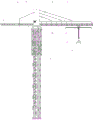
FIG. 1 is a schematic view of the overall structure of a hoisting device for prefabricated building construction according to the present invention;
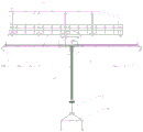
FIG. 2 is a schematic structural diagram of a stability maintaining device in the hoisting equipment for assembly type building construction of the invention;
FIG. 3 is an enlarged schematic view of region A of FIG. 2;
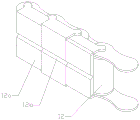
FIG. 4 is a schematic perspective view of a chain link of a U-shaped cover plate chain part in the hoisting equipment for assembly type building construction of the present invention;
fig. 5 is a schematic structural view of a peripheral angle adjusting device in the assembly type hoisting equipment for building construction according to the present invention.
Detailed Description
Embodiments of the present invention will be described in detail below with reference to the accompanying drawings. The following examples are only for illustrating the technical solutions of the present invention more clearly, and therefore are only examples, and the protection scope of the present invention is not limited thereby.
Referring to fig. 1-5, the hoisting equipment for assembly type building construction provided in this embodiment includes a sling 1, a sling retracting mechanism 2, a pull rod 3, a driver's cab 4, a balance arm 5, a counterweight 6, a boom 7, a standard knot 8, a balance plate 9, a slide rail 10 laid along the length direction of the boom 7, and a movable hanger 11 capable of moving on the slide rail 10, specifically, the counterweight 6 and the sling retracting mechanism 2 are disposed on the balance arm 5, the balance plate 9 is suspended below the movable hanger 11 through the sling 1, and slings and hooks are disposed below four corners of the balance plate 9; the device comprises two U-shaped cover plate chains 12, a chain positioning sleeve 13 vertically arranged on the movable hanging bracket 11, and two chain wheels 14 arranged on the front side and the rear side above a cylinder opening of the chain positioning sleeve 13, wherein the two chain wheels 14 are respectively correspondingly meshed with one U-shaped cover plate chain 12, each U-shaped cover plate chain 12 comprises a plurality of chain links, a connecting plate for connecting the two adjacent chain links and a U-shaped cover plate 12a, and when the U-shaped cover plate chains 12 are straightened, the adjacent U-shaped cover plates 12a are tightly attached to each other, so that the U-shaped cover plate chains 12 can only be bent to one side from a straight state; one end of each U-shaped cover plate chain 12 penetrates through the chain positioning sleeve 13 in a mode that the U-shaped cover plates 12a face back to back, vertically extends downwards along the sling 1 to the balance plate 9 and is connected with the balance plate 9, and the other end of each U-shaped cover plate chain 12 forms a free end.
As shown in fig. 5, 12 tip of two U type apron chains are provided with all angle adjusting device, two 12 tip of U type apron chains are through detachable being connected between all angle adjusting device and the balance plate 9, all angle adjusting device includes fixed disk 15, sets up at the circular carousel 16 of fixed disk lower part and drive relative pivoted driving motor 17 between fixed disk and the carousel, normal running fit between fixed disk and the carousel, be provided with round gear shaping A18 on the bottom terminal surface of carousel, spliced pole 19 has been erect at balance plate 9 middle part, spliced pole 19 top terminal surface is provided with round gear shaping B20, works as all angle adjusting device is transferred to spliced pole 19 top along with U type apron chain 12 when, as shown in fig. 5, gear shaping A18 and gear shaping B20 cooperation of pegging graft. Specifically, driving motor 17 and fixed disk 15 fixed connection, carousel 16 is circular, be provided with driven gear 21 on the carousel outer periphery, be provided with driving gear 22 on driving motor 17's the power output shaft, driving gear and driven gear intermeshing. The portable remote controller is characterized by further comprising a controller and a handheld remote controller, wherein the controller is installed on the fixed disc and is connected with the driving motor circuit, and the handheld remote controller is in wireless connection with the controller. The coaxial fixed hollow shaft 23 that is the font of falling T of longitudinal section that is provided with in the middle part of fixed disk 15, hoist cable 1 follows pass in the hollow shaft, the middle part of carousel 16 is provided with the through-hole, the carousel passes through the through-hole cover and establishes in the hollow shaft, be provided with bearing 24 between the through-hole of carousel and the hollow shaft, carousel 16 pass through bearing 24 with relative rotation between the fixed disk 15.
The working principle of the hoisting equipment for the assembly type building construction is as follows: before hoisting, the assembly type building component is fixed on a lifting hook through a lifting hook of the balance plate, the assembly type building component is hoisted by pulling a sling through a sling retracting mechanism, the height of the balance plate rises and approaches to the circumferential angle adjusting device, and finally, the gear shaping B20 at the top of the balance plate is in plug-in fit with the gear shaping A18, so that the balance plate cannot swing under the action of wind power, then the handheld remote controller controls the driving motor 17 to drive the turntable 16 to rotate, and further, the angle of the balance plate is adjusted to enable the assembly type building component to be quickly aligned to the installation position, so that the working efficiency is greatly improved, and potential safety hazards are avoided.
As a further improvement to the above technical solution, a fixed pulley 25 is further arranged above the chain positioning sleeve 13, a through groove 12b is formed in the middle of the outer surface of the U-shaped cover plate 12a of the U-shaped cover plate chain 12 along the length direction of the U-shaped cover plate chain 12, a sling channel formed by buckling the through grooves is formed between the two U-shaped cover plate chains 12 in the chain positioning sleeve 13, the diameter of the sling channel is 0.5-0.8cm larger than that of a sling, one end of the sling 1 is connected with the sling retracting mechanism 2, the other end of the sling 1 bypasses the fixed pulley 25 and then sequentially passes through the sling channel and the hollow rotating shaft, and finally is connected with the connecting column. The through groove 12b is formed in the middle of the outer surface of the U-shaped cover plate 12a, and the through groove is buckled to form a sling channel, so that a sling can pass through the sling channel without resistance.
As a further improvement to the above technical solution, a polish rod 26 is respectively disposed at the front side and the rear side of the mobile hanger 11, the polish rod 26 is disposed along the length direction of the slide rail 10, one end of the polish rod is close to the sprocket 14, the end of the other end of the polish rod has a circular arc bending head 27 formed by bending downwards, and a section of the U-shaped cover plate chain 12 close to the free end thereof is lapped on the polish rod. When the U-shaped cover chain 12 moves upward with the sling, the U-shaped cover chain 12 at the upper portion of the chain positioning sleeve 13 will move along the polish rod 26. The purpose of the improved arrangement is to avoid the U-shaped cover plate chain 12 on the upper part of the chain positioning sleeve 13 from falling below the mobile hanger 11 to obstruct the lifting.
As a further improvement to the above technical solution, the outer sides of the free end ends of the two U-shaped cover chains 12 are provided with a fixture block 28, and both sides of the mobile hanger 11 are provided with bayonets 29 for blocking the fixture block from passing through. Because the length of U type apron chain 12 is less than the length of hoist cable remarkably, through setting up the joint of fixture block 28 with bayonet 29, can realize that U type apron chain 12 can descend along with the hoist cable limitedly, when fixture block 28 and bayonet 29 joint, U type apron chain 12 will not continue to descend along with the descending of hoist cable.
As a further improvement to the technical scheme, the top of the connecting column is provided with a T-shaped head 30, the sling 1 is connected with the middle part of the end face of the T-shaped head, and the gear shaping B is arranged on the end face of the T-shaped head and surrounds the connecting part of the sling 1 and the T-shaped head for a circle. The fitting area between the turntable and the connecting column 19 can be increased by providing the T-shaped head, thereby enhancing the stability of the balance plate 9.
Finally, it should be noted that: the above examples are only intended to illustrate the technical solution of the present invention, but not to limit it; although the present invention has been described in detail with reference to the foregoing embodiments, it will be understood by those of ordinary skill in the art that: the technical solutions described in the foregoing embodiments may still be modified, or some or all of the technical features may be equivalently replaced; such modifications and substitutions do not depart from the spirit and scope of the present invention, and they should be construed as being included in the following claims and description.
Claims (9)
1. The utility model provides a lifting device for assembly type building construction, includes hoist cable, hoist cable jack, pull rod, balance arm, jib loading boom, standard festival, balance plate, along the slide rail of laying in jib loading boom length direction, can the removal gallows that removes on the slide rail, the balance plate hangs below removing the gallows through the hoist cable, its characterized in that: the device comprises a movable hanger and two U-shaped cover plate chains, and is characterized by further comprising a stability maintaining device, wherein the stability maintaining device comprises two U-shaped cover plate chains, a chain positioning sleeve vertically arranged on the movable hanger, and two chain wheels arranged on the front side and the rear side above a cylinder opening of the chain positioning sleeve, the two chain wheels are respectively and correspondingly meshed with one U-shaped cover plate chain, one ends of the two U-shaped cover plate chains penetrate through the chain positioning sleeve in a back-to-back mode and vertically extend downwards to the balance plate along a sling to be connected with the balance plate, and the other ends of the two U-shaped cover plate chains form free ends.
2. The hoisting device for assembly type building construction according to claim 1, wherein: two U type apron chain tip are provided with all angle adjusting device, two U type apron chain tip are through detachable being connected between all angle adjusting device and the balance plate, all angle adjusting device includes the fixed disk, sets up between the circular shape carousel of fixed disk lower part and drive fixed disk and the carousel relative pivoted driving motor, normal running fit between fixed disk and the carousel, be provided with round gear shaping A on the bottom terminal surface of carousel, the spliced pole has been erect at the balance plate middle part, spliced pole top terminal surface is provided with round gear shaping B, works as when all angle adjusting device transfers the spliced pole top along with U type apron chain, gear shaping A and gear shaping B cooperation of pegging graft.
3. The hoisting equipment for assembly type building construction according to claim 2, wherein: the driving motor is fixedly connected with the fixed disc, the rotary disc is circular, a driven gear is arranged on the outer circumferential surface of the rotary disc, a driving gear is arranged on a power output shaft of the driving motor, and the driving gear is meshed with the driven gear.
4. The hoisting equipment for assembly type building construction according to claim 3, wherein: the middle part of fixed disk is coaxial fixed to be provided with the hollow rotating shaft that the longitudinal section is the font of falling T, the hoist cable is followed pass in the hollow rotating shaft, the middle part of carousel is provided with the through-hole, the carousel passes through the through-hole cover to be established in hollow rotating shaft, be provided with the bearing between the through-hole of carousel and the hollow rotating shaft, the carousel pass through the bearing with relative rotation between the fixed disk.
5. The hoisting equipment for assembly type building construction according to claim 4, wherein: the chain positioning sleeve top still is provided with the fixed pulley, logical groove has been seted up on the length direction of U type apron chain is followed at the U type apron surface middle part of U type apron chain, forms the hoist cable passageway that is formed by leading to the groove lock between two U type apron chains in the chain positioning sleeve, the one end and the hoist cable jack of hoist cable are connected, and the other end passes in proper order from hoist cable passageway and hollow rotating shaft after walking around the fixed pulley, is connected with the spliced pole at last.
6. The hoisting equipment for assembly type building construction according to claim 5, wherein: the front side and the rear side of the movable hanging bracket are respectively provided with a polished rod, the polished rods are arranged along the length direction of the sliding rail, one end of each polished rod is close to the chain wheel, the end part of the other end of each polished rod is provided with a circular arc-shaped bending head formed by downward bending, and one section of the U-shaped cover plate chain, which is close to the free end of the U-shaped cover plate chain, is lapped on the polished rod.
7. The hoisting equipment for assembly type building construction according to claim 6, wherein: and clamping blocks are arranged on the outer sides of the free end parts of the two U-shaped cover plate chains, and bayonets for blocking the clamping blocks to pass through are arranged on the two sides of the movable hanging bracket.
8. The hoisting device for assembly type building construction according to claim 7, wherein: the top of the connecting column is provided with a T-shaped head, the sling is connected with the middle part of the end face of the T-shaped head, and the gear shaping B is arranged on the end face of the T-shaped head and surrounds the connecting part of the sling and the T-shaped head to form a circle.
9. The hoisting device for assembly type building construction according to claim 8, wherein: the portable remote controller is characterized by further comprising a controller and a handheld remote controller, wherein the controller is installed on the fixed disc and is connected with the driving motor circuit, and the handheld remote controller is in wireless connection with the controller.
Priority Applications (1)
| Application Number | Priority Date | Filing Date | Title |
|---|---|---|---|
| CN202111320855.9A CN113955636A (en) | 2021-11-09 | 2021-11-09 | Hoisting equipment for assembly type building construction |
Applications Claiming Priority (1)
| Application Number | Priority Date | Filing Date | Title |
|---|---|---|---|
| CN202111320855.9A CN113955636A (en) | 2021-11-09 | 2021-11-09 | Hoisting equipment for assembly type building construction |
Publications (1)
| Publication Number | Publication Date |
|---|---|
| CN113955636A true CN113955636A (en) | 2022-01-21 |
Family
ID=79469829
Family Applications (1)
| Application Number | Title | Priority Date | Filing Date |
|---|---|---|---|
| CN202111320855.9A Withdrawn CN113955636A (en) | 2021-11-09 | 2021-11-09 | Hoisting equipment for assembly type building construction |
Country Status (1)
| Country | Link |
|---|---|
| CN (1) | CN113955636A (en) |
Cited By (1)
| Publication number | Priority date | Publication date | Assignee | Title |
|---|---|---|---|---|
| CN117682421B (en) * | 2024-02-04 | 2024-04-30 | 河南斯玛特起重机有限公司 | Hoist tilting prevention device of crane |
-
2021
- 2021-11-09 CN CN202111320855.9A patent/CN113955636A/en not_active Withdrawn
Cited By (1)
| Publication number | Priority date | Publication date | Assignee | Title |
|---|---|---|---|---|
| CN117682421B (en) * | 2024-02-04 | 2024-04-30 | 河南斯玛特起重机有限公司 | Hoist tilting prevention device of crane |
Similar Documents
| Publication | Publication Date | Title |
|---|---|---|
| CN112340599B (en) | Freely-adjustable assembly type hoisting device for building wallboard | |
| CN105003082A (en) | Glass curtain wall mounting equipment and glass curtain mounting method | |
| CN210012529U (en) | Hoist and mount welding equipment suitable for heavy object lifts by crane | |
| CN108756199A (en) | Attached lifting scaffold lifting gear | |
| CN214879790U (en) | Movable arm tower crane | |
| CN212374757U (en) | Tower crane stable in installation | |
| CN208429786U (en) | A kind of cold-strip steel lifting machine | |
| CN113955636A (en) | Hoisting equipment for assembly type building construction | |
| CN215905709U (en) | External wall panel hoisting device for assembly type building construction | |
| CN214935537U (en) | Construction equipment for quickly installing roadbed side ditch cover plate | |
| CN209942208U (en) | Pulley type front-hung hoist mounting structure for climbing frame lifting | |
| CN210885011U (en) | Multifunctional crane assembled on forklift | |
| CN220618162U (en) | Underground hydraulic support lifting device for green mining of coal mine | |
| CN213387523U (en) | Rotary hoisting device | |
| CN219217505U (en) | Portable apron hoist device | |
| CN219219846U (en) | Plate loading machine | |
| CN220033837U (en) | Safe lifting equipment | |
| CN214733964U (en) | Multifunctional hoisting machine | |
| CN220434239U (en) | Portable movable freely adjusts vertical height's lifting and pouring car | |
| CN217894899U (en) | Pipeline mobile device for hydraulic engineering | |
| CN219823394U (en) | Novel blast furnace skip hoist and mount device | |
| CN219314434U (en) | Precast concrete board loading and unloading device | |
| CN220148996U (en) | Assembled building board hoist device | |
| CN220283436U (en) | Hoisting mechanism, wind power device thereof and full-automatic tower crane | |
| CN212245985U (en) | Single-arm glass hanger |
Legal Events
| Date | Code | Title | Description |
|---|---|---|---|
| PB01 | Publication | ||
| PB01 | Publication | ||
| SE01 | Entry into force of request for substantive examination | ||
| SE01 | Entry into force of request for substantive examination | ||
| WW01 | Invention patent application withdrawn after publication |
Application publication date: 20220121 |
|
| WW01 | Invention patent application withdrawn after publication |