CN113928362A - Framework device for built-in non-power bogie of axle box of high-speed motor train unit - Google Patents
Framework device for built-in non-power bogie of axle box of high-speed motor train unit Download PDFInfo
- Publication number
- CN113928362A CN113928362A CN202111330958.3A CN202111330958A CN113928362A CN 113928362 A CN113928362 A CN 113928362A CN 202111330958 A CN202111330958 A CN 202111330958A CN 113928362 A CN113928362 A CN 113928362A
- Authority
- CN
- China
- Prior art keywords
- side beam
- seat
- mounting seat
- forged
- box
- Prior art date
- Legal status (The legal status is an assumption and is not a legal conclusion. Google has not performed a legal analysis and makes no representation as to the accuracy of the status listed.)
- Granted
Links
- 238000003466 welding Methods 0.000 claims abstract description 58
- 230000007704 transition Effects 0.000 claims abstract description 48
- 239000000725 suspension Substances 0.000 claims abstract description 16
- 239000006096 absorbing agent Substances 0.000 claims description 37
- 230000035939 shock Effects 0.000 claims description 37
- 238000005242 forging Methods 0.000 claims description 29
- 230000007246 mechanism Effects 0.000 claims description 19
- 238000005096 rolling process Methods 0.000 claims description 18
- 238000003801 milling Methods 0.000 claims description 7
- 239000000956 alloy Substances 0.000 claims description 6
- 229910000838 Al alloy Inorganic materials 0.000 claims description 5
- 230000000694 effects Effects 0.000 abstract description 6
- 241000271559 Dromaiidae Species 0.000 abstract description 2
- 238000004519 manufacturing process Methods 0.000 description 10
- 238000000034 method Methods 0.000 description 10
- 238000012423 maintenance Methods 0.000 description 7
- 230000008569 process Effects 0.000 description 6
- 229910000831 Steel Inorganic materials 0.000 description 5
- 239000010959 steel Substances 0.000 description 5
- 238000009434 installation Methods 0.000 description 4
- 230000007547 defect Effects 0.000 description 3
- 229910003460 diamond Inorganic materials 0.000 description 3
- 239000010432 diamond Substances 0.000 description 3
- 238000005299 abrasion Methods 0.000 description 2
- 238000013016 damping Methods 0.000 description 2
- 230000009286 beneficial effect Effects 0.000 description 1
- 230000008859 change Effects 0.000 description 1
- 238000006073 displacement reaction Methods 0.000 description 1
- 238000002474 experimental method Methods 0.000 description 1
- 239000002360 explosive Substances 0.000 description 1
- 229910001095 light aluminium alloy Inorganic materials 0.000 description 1
- 239000000463 material Substances 0.000 description 1
- 239000011159 matrix material Substances 0.000 description 1
- 230000009467 reduction Effects 0.000 description 1
- 230000008439 repair process Effects 0.000 description 1
- 230000007306 turnover Effects 0.000 description 1
- 239000013585 weight reducing agent Substances 0.000 description 1
Images


Classifications
-
- B—PERFORMING OPERATIONS; TRANSPORTING
- B61—RAILWAYS
- B61F—RAIL VEHICLE SUSPENSIONS, e.g. UNDERFRAMES, BOGIES OR ARRANGEMENTS OF WHEEL AXLES; RAIL VEHICLES FOR USE ON TRACKS OF DIFFERENT WIDTH; PREVENTING DERAILING OF RAIL VEHICLES; WHEEL GUARDS, OBSTRUCTION REMOVERS OR THE LIKE FOR RAIL VEHICLES
- B61F5/00—Constructional details of bogies; Connections between bogies and vehicle underframes; Arrangements or devices for adjusting or allowing self-adjustment of wheel axles or bogies when rounding curves
- B61F5/26—Mounting or securing axle-boxes in vehicle or bogie underframes
- B61F5/30—Axle-boxes mounted for movement under spring control in vehicle or bogie underframes
- B61F5/301—Axle-boxes mounted for movement under spring control in vehicle or bogie underframes incorporating metal springs
-
- B—PERFORMING OPERATIONS; TRANSPORTING
- B61—RAILWAYS
- B61F—RAIL VEHICLE SUSPENSIONS, e.g. UNDERFRAMES, BOGIES OR ARRANGEMENTS OF WHEEL AXLES; RAIL VEHICLES FOR USE ON TRACKS OF DIFFERENT WIDTH; PREVENTING DERAILING OF RAIL VEHICLES; WHEEL GUARDS, OBSTRUCTION REMOVERS OR THE LIKE FOR RAIL VEHICLES
- B61F5/00—Constructional details of bogies; Connections between bogies and vehicle underframes; Arrangements or devices for adjusting or allowing self-adjustment of wheel axles or bogies when rounding curves
- B61F5/26—Mounting or securing axle-boxes in vehicle or bogie underframes
- B61F5/30—Axle-boxes mounted for movement under spring control in vehicle or bogie underframes
- B61F5/307—Axle-boxes mounted for movement under spring control in vehicle or bogie underframes incorporating fluid springs
-
- B—PERFORMING OPERATIONS; TRANSPORTING
- B61—RAILWAYS
- B61F—RAIL VEHICLE SUSPENSIONS, e.g. UNDERFRAMES, BOGIES OR ARRANGEMENTS OF WHEEL AXLES; RAIL VEHICLES FOR USE ON TRACKS OF DIFFERENT WIDTH; PREVENTING DERAILING OF RAIL VEHICLES; WHEEL GUARDS, OBSTRUCTION REMOVERS OR THE LIKE FOR RAIL VEHICLES
- B61F5/00—Constructional details of bogies; Connections between bogies and vehicle underframes; Arrangements or devices for adjusting or allowing self-adjustment of wheel axles or bogies when rounding curves
- B61F5/26—Mounting or securing axle-boxes in vehicle or bogie underframes
- B61F5/30—Axle-boxes mounted for movement under spring control in vehicle or bogie underframes
- B61F5/308—Axle-boxes mounted for movement under spring control in vehicle or bogie underframes incorporating damping devices
-
- B—PERFORMING OPERATIONS; TRANSPORTING
- B61—RAILWAYS
- B61F—RAIL VEHICLE SUSPENSIONS, e.g. UNDERFRAMES, BOGIES OR ARRANGEMENTS OF WHEEL AXLES; RAIL VEHICLES FOR USE ON TRACKS OF DIFFERENT WIDTH; PREVENTING DERAILING OF RAIL VEHICLES; WHEEL GUARDS, OBSTRUCTION REMOVERS OR THE LIKE FOR RAIL VEHICLES
- B61F5/00—Constructional details of bogies; Connections between bogies and vehicle underframes; Arrangements or devices for adjusting or allowing self-adjustment of wheel axles or bogies when rounding curves
- B61F5/50—Other details
- B61F5/52—Bogie frames
Landscapes
- Engineering & Computer Science (AREA)
- Mechanical Engineering (AREA)
- Vehicle Body Suspensions (AREA)
Abstract
Framework device for built-in non-power bogie of high-speed EMUs axle box belongs to rail vehicle bogie framework device field, and it includes: the device comprises a combined side beam consisting of a box-type welded side beam and a forged side beam, a forged cross beam, a lightweight integrated mounting seat, a transverse straight gear, a side beam brake cylinder hanging seat, a rotating arm positioning seat, two cross beam brake cylinder hanging seats and a traction pull rod seat; the two combined side beams and the two forged cross beams constitute a framework. By means of the characteristics of high structural strength and small thickness of the forged side beam, the cantilever mass and the occupied longitudinal space when the wing-shaped transition seat of the side beam extends outwards originally are greatly reduced, the effects of reducing weight of a far end and increasing layout space of a series of suspension plate springs and clamp braking units are achieved while the structural strength is guaranteed, the welding workload is remarkably reduced, a thermal deformation area is welded, and the mechanical strength and quality of a welding seam are improved.
Description
Technical Field
The invention belongs to the field of bogie frame devices of railway vehicles, and particularly relates to a frame device for a built-in non-power bogie of an axle box of a high-speed motor train unit.
Background
The bogie frame is one of key parts of the rail transit vehicle for bearing the weight of the vehicle body and transmitting the acting force between the wheel rail and the vehicle body; the framework is required to bear the tasks of installing components such as wheel sets, traction devices, primary suspensions, secondary suspensions, shock absorbers, braking units and the like while bearing and transmitting force, so that other components can be well realized, and interference is avoided under certain displacement; the frame must therefore have good strength, rigidity and stability, so that the rail transit vehicle can run quickly, flexibly, safely, stably and smoothly along the rails.
The traditional framework is generally in an axle box external form that an axle box mechanism is positioned on the outer side of a wheel, and more cantilever type axle boxes with rubber cantilever nodes are adopted, the framework is large in size and heavy in mass and has poor adaptability to continuous large-angle twisted road sections of a track line, moreover, the framework mass belongs to the mass between springs, the larger framework weight can enable loads borne by wheel sets and a train body to be increased sharply when a train runs at a high speed, the abrasion of wheel tracks is large, the running and maintenance cost is high, and the running stability and comfort of the train are influenced. Compared with a wide and heavy axle box external framework, the axle box internal framework has the advantages of small volume and light weight, but the side beam of the framework is arranged on the inner sides of two wheel pairs and is limited by the distance between the inner sides of the wheel pairs, the arrangement transverse space of auxiliary equipment such as a traction center, a braking mechanism and the like is extremely tight, the space arrangement of the auxiliary equipment arranged on the framework is compact, the assembly and maintenance are difficult, and the assembly space cannot be reserved for newly added functional parts.
For designing a high-speed motor train unit train with the speed per hour exceeding 400 kilometers, the stress condition of a bogie frame is more complex, and therefore, in consideration of structural strength and safety, the existing high-speed motor train unit train bogie adopts an axle box external box type all-welded frame which is large in overall frame size and weight, large in welding line quantity, serious in welding deformation and poor in flexibility. And the axle box built-in framework with small volume and light weight is difficult to be applied to the high-speed motor train unit train with the designed speed per hour exceeding 400 kilometers.
Disclosure of Invention
In order to solve the problems that the existing framework for the bogie for the high-speed motor train unit with the speed per hour exceeding 400 kilometers adopts an axle box external box type all-welded framework with high structural strength, the framework of the wheel rail welding machine is faced with the problems of large size and weight of the whole framework, large number of welding lines, serious welding deformation, large adjustment and repair difficulty, poor flexibility of the framework, severe abrasion of the wheel rail and the like, the existing weight reduction design of the other axle box built-in type framework is difficult to achieve reasonable balance among higher structural strength of the framework, better vibration reduction and diamond load bearing capacity and lighter overall mass of the framework, and the space size of the air springs and the internal clearance space of the integral framework are smaller, so that the transverse layout space of auxiliary equipment such as traction equipment, braking equipment and the like is too compact, the assembly and maintenance are difficult, and the assembly space cannot be reserved for newly added functional parts.
The technical scheme adopted by the invention for solving the technical problem is as follows:
frame device for built-in non-power bogie of high-speed EMUs axle box, it includes: the device comprises a combined side beam consisting of a box-type welded side beam and a forged side beam, a forged cross beam, a lightweight integrated mounting seat, a transverse straight gear, a side beam brake cylinder hanging seat, a rotating arm positioning seat, two cross beam brake cylinder hanging seats and a traction pull rod seat; the two combined side beams and the two forged cross beams form a framework;
the middle part of the box-type welding side beam protrudes outwards, an air spring mounting seat on the box-type welding side beam is arranged at the position where the middle part protrudes outwards, and the axis of a central hole of the air spring mounting seat is vertically upward; a series of vertical shock absorber mounting seats are arranged on the inner side wall of one end of the forged side beam, a series of suspension plate spring mounting seats are arranged on the lower side wall of the end of the forged side beam, an L-shaped transition connecting plate is arranged at the other end of the forged side beam, and the forged side beam is fixedly connected with the end part of a wing-shaped transition seat of the side beam of the box-type welded side beam through the L-shaped transition connecting plate in a welding manner;
the lightweight integrated mounting seat is fixedly connected to the outer side wall protruding outwards from the middle part of the box-type welding side beam, the transverse straight baffle is fixedly connected to the inner side wall in the middle part of the box-type welding side beam, the side beam brake cylinder hanging seats are fixedly connected to the inner side wall of the side beam wing-shaped transition seat, the rotating arm positioning seat is fixedly connected to the lower side wall of the side beam wing-shaped transition seat, the two crossbeam brake cylinder hanging seats are fixedly connected to the outer side walls in the middle parts of the two forged crossbeam cross beam pipes in a one-to-one correspondence manner, the traction pull rod seats are fixedly connected to the lower side wall at one end of each forged crossbeam cross beam pipe, and the two traction pull rod seats are rotationally and symmetrically arranged by taking the center of a framework as the center;
two forging crossbeams are fixedly connected to the inner side wall in the middle of the box-type welding side beam through transition connecting plates at two ends, the two forging crossbeams are located on two sides of the transverse straight gear, a transverse shock absorber mounting seat is arranged on the upper side wall of one transition connecting plate of each forging crossbeam, and the two transverse shock absorber mounting seats are arranged in a rotational symmetry mode by taking the center of the framework as the center.
The traction pull rod seat comprises a half integrated traction pull rod seat and a half independent traction pull rod seat, the half integrated traction pull rod seat and the transition connecting plate are integrally machined and formed through forging and milling processes, and the half independent traction pull rod seat is welded on the beam pipe; each forged crossbeam and a corresponding crossbeam brake cylinder hanging seat fixedly connected with the forged crossbeam and a corresponding traction pull rod seat fixedly connected with the forged crossbeam form a crossbeam mechanism together; each combined side beam and a corresponding lightweight integrated mounting seat fixedly connected to the outer side wall of the combined side beam, and eight transverse straight baffles, two side beam brake cylinder hanging seats and two rotating arm positioning seats fixedly connected to the inner side wall of the combined side beam form a side beam mechanism together.
The lightweight integrated mounting seat is fixedly connected to the outer side wall protruding outwards in the middle of the box-type welding side beam through bolts, and the transverse straight gear is fixedly connected to the inner side wall in the middle of the box-type welding side beam through bolts.
The connecting section of the transition connecting plate of the forged side beam and the transition connecting section primary suspension plate spring mounting seat is an outward-inclined cantilever which extends towards the outside of the side beam in a horizontal plane in an inclined manner; a first included angle formed by the side wall of the outward-inclined cantilever and the outer end face of the wing-shaped transition seat of the side beam is beta, the value range of the first included angle beta is 3-9 degrees, and the optimal value is 5 degrees; the two forged side beams are positioned at the same longitudinal end part of the combined side beam, a second included angle formed by the outer end faces of wing-shaped transition seats of the two forged side beams is alpha, the angle range of the second included angle alpha is 6-18 degrees, and the optimal value of the second included angle alpha is 10 degrees; the base of the brake cylinder hanging seat of the side beam is cylindrical, a third included angle gamma between the rotation axis of the base and the transverse center line s of the combined side beam ranges from 3 degrees to 8 degrees, and the optimal value is 5 degrees.
The lightweight integrated mounting seat comprises an integrally formed anti-side-rolling torsion bar mounting seat, an anti-snaking shock absorber mounting seat and a secondary vertical shock absorber mounting seat; the overlooking structure of the lightweight integrated mounting seat is triangular, and the connecting line of the axle seat centroids of the anti-rolling torsion bar mounting seat and the secondary vertical shock absorber mounting seat is parallel to the combined side beam; an anti-snaking damper mounting seat positioned at the other vertex of the triangular structure, and the opening of the anti-snaking damper mounting seat faces the outside of the combined side beam; the opening of the anti-rolling torsion bar mounting seat is parallel to the combined side beam; the opening direction of the secondary vertical shock absorber mounting seat is parallel to the rotation axis of the forging crossbeam; the rotation axis of the anti-rolling torsion bar mounting seat self-mounting shaft seat and the rotation axis of the secondary vertical shock absorber mounting seat self-mounting shaft seat are parallel to the axial direction of the air spring mounting seat shaft hole; the anti-snake-like vibration damper mounting seat is provided with a rotation axis of a shaft seat, an axis of an air spring mounting seat and a rotation axis of a forging cross beam, and the three rotation axes are perpendicular to each other in a different plane.
The lightweight integrated mounting seat is made of a lightweight aluminum alloy material and is integrally machined and formed through forging and milling processes, and a lightening hole is formed in the middle of the lightweight integrated mounting seat.
The invention has the beneficial effects that: according to the framework device for the built-in non-power bogie of the axle box of the high-speed motor train unit, the cross section of a box-shaped welding side beam protruding outwards from the middle part of the box-shaped welding side beam is gradually increased from two ends to the middle part, the variable cross section design can enhance the capacity of the framework for resisting diamond load integrally, can effectively increase the spacing value of air springs on two combined side beams, and increases the mass of the springs along the transverse extension of the framework, so that the framework device is an arrangement space expanded for original compact auxiliary equipment such as air springs, traction centers and the like, and the torque damping value between two anti-side-rolling torsion rod seats of the light-weight integrated mounting seat is improved.
Forge the curb girder and pass through L shape transition connecting plate and box welding curb girder's the welding of the winged transition seat tip of curb girder and link firmly to with the help of forging the characteristic that curb girder self structural strength is high and thickness is little, cantilever quality and the vertical space that occupies when having reduced originally by the winged transition seat of curb girder outwards to extend by a wide margin, and then play the distal end when guaranteeing structural strength and subtract heavy and increase the effect in a series of suspension plate spring and clamp braking unit overall arrangement space, and show and reduce welding operation volume, the welding heat deflection region, improve welding seam mechanical strength and quality.
The transverse shock absorber mounting seat and the transition connecting plate are combined into a structural design of a forging integrated piece, so that the process steps that the conventional transverse shock absorber is separately welded with a beam pipe in a beam brake cylinder hanging seat mode are reduced, the thermal shrinkage deformation and the welding defect generation probability of a welding and fixing mode are reduced, and the welding manufacturing and adjusting and repairing processes are reduced; the layout mode of rotational symmetry can make the reverse torques generated in the form of rotational symmetry on the framework offset each other, and the effect of reducing the snaking torsion is realized.
The transition connecting plate and the half integrated traction pull rod seat are combined into a forged integral piece, so that the process steps of independently welding the two independent traction pull rod seats with the beam pipe in the prior art are reduced, the thermal shrinkage deformation and the welding defect generation probability of a welding and fixing mode are reduced, and the welding manufacturing and adjusting and repairing processes are reduced.
The lightweight integrated mounting seat is fixedly connected to the outer side wall protruding outwards in the middle of the box-type welding side beam through bolts, so that the thermal shrinkage deformation and the welding flaw generation probability of a welding and fixing mode are reduced, welding manufacturing and adjusting and repairing processes are reduced, and the production, maintenance and replacement efficiency is improved.
The transition connecting plate is connected with a series of suspension plate spring mounting seats through an outward-inclined cantilever, the outward-inclined cantilever extends towards the outer part of the side beam in a horizontal plane in an inclined manner, and the angle range of a first included angle beta formed between the outward-inclined cantilever and the outer end face of the wing-shaped transition seat of the side beam is 3 degrees to 9 degrees, and the optimal value is 5 degrees; the angle range of a second included angle alpha formed by the outer end faces of wing-shaped transition seats of the two forged side beams positioned at the same longitudinal end part of the combined side beam is 6 degrees to 18 degrees, and the optimal value of the angle alpha is 10 degrees; the base of the brake cylinder hanging seat of the side beam is cylindrical, a third included angle gamma between the rotation axis of the base and the transverse center line s of the combined side beam ranges from 3 degrees to 8 degrees, and the optimal value is 5 degrees. The parameter setting of the size chain is verified and determined by a large number of experiments, the parameter design of the size chain enables the distance value between the far ends of the two side beam mechanisms to be remarkably increased, the layout space of the primary vertical shock absorber mounting seat and the primary suspension plate spring is improved, and therefore the crowding of the primary suspension device on the transverse space of the framework is released. The compact and staggered structure enables the respective distance values of the beam brake cylinder hanging seats and the two side beam brake cylinder hanging seats to be remarkably increased, layout space is improved, the maximum number of the shaft-mounted brake disc mechanisms arranged along the axle is increased from two old to three, the braking effect of the shaft-mounted brake mechanism is further enhanced, a train running at high speed has a smaller braking distance, and performance and safety of the train are improved. In addition, this structural design makes originally arrange in the cantilever type axle box in the left and right steel wheel outside of wheel pair mechanism to change and arrange in the relative inboard of left and right steel wheel to effectively shortened the theoretical span of forging the crossbeam, the moment of torsion of whole framework reduces, and intensity is higher.
The overlooking structure of the lightweight integrated mounting seat is triangular, and the connecting line of the axle seat centroids of the anti-rolling torsion bar mounting seat and the secondary vertical shock absorber mounting seat is parallel to the combined side beam; an anti-snaking damper mounting seat positioned at the other vertex of the triangular structure, and the opening of the anti-snaking damper mounting seat faces the outside of the combined side beam; the opening of the anti-rolling torsion bar mounting seat is parallel to the combined side beam; the opening direction of the secondary vertical shock absorber mounting seat is parallel to the rotation axis of the forging crossbeam; the rotation axis of the anti-rolling torsion bar mounting seat self-mounting shaft seat and the rotation axis of the secondary vertical shock absorber mounting seat self-mounting shaft seat are parallel to the axial direction of the air spring mounting seat shaft hole; the anti-snake-like vibration damper mounting seat is provided with a rotation axis of a shaft seat, an axis of an air spring mounting seat and a rotation axis of a forging cross beam, and the three rotation axes are perpendicular to each other in a different plane. The structural design moves the anti-rolling torsion bar, the anti-snaking shock absorber and the secondary vertical shock absorber to the outside of the framework from the inside of the framework, so that the layout space inside the framework is better released, the assembly and the maintenance of the auxiliary parts of the framework are convenient, and the assembly space is reserved for the newly added functional parts. The lightweight integrated mounting seat is made of a lightweight aluminum alloy material and is integrally machined and formed through forging and milling, and a lightening hole is formed in the middle of the lightweight integrated mounting seat. The structural design greatly reduces the self weight of the lightweight integrated mounting seat, saves the manufacturing cost and the assembling time, and enables the application of the lightweight aluminum alloy material to be possible while ensuring the structural strength.
Drawings
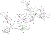
FIG. 1 is a perspective view of a frame device for a built-in non-powered bogie of an axle box of a high-speed motor train unit;
FIG. 2 is a schematic illustration of the explosive assembly of FIG. 1;
FIG. 3 is a schematic perspective view of a frame device for a built-in non-powered bogie of an axle box of a high-speed motor train unit under a turnover view angle;
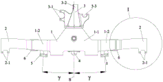
FIG. 4 is a top view of the frame device for the axle box built-in non-power bogie of the high-speed motor train unit;
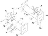
FIG. 5 is a schematic perspective view of two cross-beam mechanisms;
FIG. 6 is a top plan view of the side beam mechanism of the present invention;
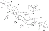
FIG. 7 is an exploded assembly view of the side beam mechanism of the present invention from a perspective view;
fig. 8 is a partially enlarged view of a portion I of fig. 6;
FIG. 9 is a schematic view of the assembled relationship of the box-type welded side beams and two swivel arm positioning bases of the present invention;
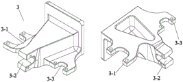
fig. 10 is a schematic perspective view of the lightweight integrated mount of the present invention from a different perspective.
Detailed Description
The present invention will be described in further detail with reference to the accompanying drawings.
As shown in fig. 1 to 10, the frame device for a high-speed motor train unit axle box built-in type non-power bogie of the present invention includes: the device comprises a combined side beam consisting of a box-type welded side beam 1 and a forged side beam 2, a forged cross beam 7, a lightweight integrated mounting seat 3, a transverse straight baffle 4, a side beam brake cylinder hanging seat 5, a rotary arm positioning seat 6, two cross beam brake cylinder hanging seats 8 and a traction pull rod seat 9; the two combined side members and the two forged cross members 7 constitute a framework.
The middle part of the box-type welding side beam 1 protrudes outwards, an air spring mounting seat 1-1 on the box-type welding side beam 1 is arranged at the position where the middle part protrudes outwards, and the axis of a central hole of the air spring mounting seat is vertically upward; the outer side protruding structure enables the cross section of the box-type welding side beam 1 to be gradually increased from two ends to the middle part, the variable cross section design can not only enhance the capacity of the whole framework for resisting diamond load, but also effectively increase the spacing value of air springs on two combined side beams, the quantity of the spring matrix extends along the transverse direction of the framework, the arrangement space is expanded for the original compact auxiliary equipment such as air springs, traction centers and the like, and the torque damping value between the two anti-side-rolling torsion rod seats of the light-weight integrated mounting seat 3 is improved; a series of vertical shock absorber mounting seats 2-1 are arranged on the inner side wall of one end of the forged side beam 2, a series of suspension plate spring mounting seats 2-2 are arranged on the lower side wall of the end, an L-shaped transition connecting plate 2-3 is arranged at the other end of the forged side beam 2, the forged side beam 2 is fixedly connected with the end part of the side beam wing-shaped transition seat 1-2 of the box-shaped welded side beam 1 through the L-shaped transition connecting plate 2-3, therefore, by means of the characteristics of high structural strength and small thickness of the forged side beam 2, the cantilever mass and the occupied longitudinal space when the wing-shaped transition seats 1-2 of the side beam extend outwards originally are greatly reduced, thereby achieving the functions of reducing weight at the far end and increasing the layout space of the vertical shock absorber 10 and the suspension plate spring 11 while ensuring the structural strength, and the welding workload and the welding thermal deformation area are obviously reduced, and the mechanical strength and the quality of the welding seam are improved.
The lightweight integrated mounting seat 3 is fixedly connected to the outer side wall protruding outwards from the middle of the box-type welding side beam 1, the transverse straight baffle 4 is fixedly connected to the inner side wall at the middle of the box-type welding side beam 1, the side beam brake cylinder hanging seats 5 are fixedly connected to the inner side wall of the wing-shaped transition seats 1-2 of the side beam, the rotating arm positioning seat 6 is fixedly connected to the lower side wall of the wing-shaped transition seats 1-2 of the side beam, the two crossbeam brake cylinder hanging seats 8 are fixedly connected to the outer side wall at the middle of the crossbeam pipes 7-1 of the two forged crossbeams 7 in a one-to-one correspondence manner, the traction pull rod seat 9 is fixedly connected to the lower side wall at one end of the crossbeam pipe 7-1 of the forged crossbeams 7, and the two traction pull rod seats 9 are rotationally and symmetrically arranged by taking the center of a framework as the center.
Two forging cross beams 7 are fixedly connected to the inner side wall of the middle part of the box-type welding side beam 1 through transition connecting plates 7-2 at two ends, the two forging cross beams 7 are positioned at two sides of the transverse straight baffle 4, the upper side wall of one transition connecting plate 7-2 of each forging cross beam 7 is provided with a transverse shock absorber mounting seat 7-2-1, and the two transverse shock absorber mounting seats 7-2-1 are rotationally and symmetrically arranged by taking the center of the framework as the center. The structural design that the transverse shock absorber mounting seat 7-2-1 and the transition connecting plate 7-2 are combined into a forging integrated piece reduces the process steps that the prior transverse shock absorber is separately welded with the beam tube 7-1 in the form of the beam brake cylinder hanging seat 8, thereby reducing the thermal shrinkage deformation amount of a welding and fixing mode and the generation probability of welding flaws, and reducing the welding manufacturing and repairing processes; the layout mode of rotational symmetry can make the reverse torques generated in the form of rotational symmetry on the framework offset each other, and the effect of reducing the snaking torsion is realized.
The traction pull rod seat 9 comprises a half integrated traction pull rod seat 9-1 and a half independent traction pull rod seat 9-2, the half integrated traction pull rod seat 9-1 and the transition connecting plate 7-2 are integrally processed and molded through forging and milling processes, the transition connecting plate 7-2 and the half integrated traction pull rod seat 9-1 are combined into a forging integrated piece, and the process steps that the two old independent traction pull rod seats 9-2 are independently welded with the beam tube 7-1 are reduced, so that the thermal shrinkage deformation of a welding and fixing mode and the generation probability of welding defects are reduced, and the welding manufacturing and adjusting and repairing processes are reduced; the other half of the independent traction pull rod seat 9-2 is welded on the beam pipe 7-1.
Each forged crossbeam 7, a corresponding crossbeam brake cylinder hanging seat 8 fixedly connected to the forged crossbeam and a corresponding traction pull rod seat 9 fixedly connected to the forged crossbeam form a crossbeam mechanism together; each combined side beam and a corresponding lightweight integrated mounting seat 3 fixedly connected to the outer side wall of the combined side beam, and two transverse straight baffles 4, two side beam brake cylinder hanging seats 5 and two rotating arm positioning seats 6 fixedly connected to the inner side wall of the combined side beam form a side beam mechanism together.
The lightweight integrated mounting seat 3 is fixedly connected to the outer side wall protruding outwards in the middle of the box-type welding side beam 1 through bolts, and the transverse straight gear 4 is fixedly connected to the inner side wall in the middle of the box-type welding side beam 1 through bolts. Therefore, the thermal shrinkage deformation and the welding flaw generation probability of the welding fixed connection mode are reduced, the welding manufacturing and adjusting and repairing processes are reduced, and the production, maintenance and replacement efficiency is improved.
The connecting section of a transition connecting plate 2-3 of the forged side beam 2 and a transition connecting section primary suspension plate spring mounting seat 2-2 is a camber cantilever 2-4, and the camber cantilever 2-4 extends towards the outside of the side beam in a horizontal plane in an inclined manner; a first included angle formed by the side wall of the outward-inclined cantilever 2-4 and the outer end face of the side beam wing-shaped transition seat 1-2 is beta, the value range of the first included angle beta is 3 degrees to 9 degrees, and the optimal value is 5 degrees; the two forged side beams 2 are positioned at the same longitudinal end part of the combined side beam, the outer end faces of wing-shaped transition seats 1-2 of the two forged side beams respectively form a second included angle alpha, the range of the angle of the second included angle alpha is 6-18 degrees, and the optimal value of the angle is 10 degrees; the structural design enables the distance value between the far ends of the two side beam mechanisms to be obviously increased, and the layout space of the primary vertical shock absorber 10 and the primary suspension plate spring 11 is improved, so that the crowding of the primary suspension device on the transverse space of the framework is released; in addition, the cantilever type axle box 13 originally arranged on the outer sides of the left and right steel wheels 12-2 of the wheel pair mechanism 12 is changed to be arranged on the opposite inner sides of the left and right steel wheels 12-2 through the structural design, so that the theoretical span of the forged cross beam 7 is effectively shortened, the torque of the whole framework is reduced, and the strength is higher.
The base of the side beam brake cylinder hanging seat 5 is cylindrical, a third included angle gamma between the rotation axis of the base and the transverse center line s of the combined side beam ranges from 3 degrees to 8 degrees, and the optimal value is 5 degrees. The structure that this structural design made curb girder brake jar hanging seat 5 and crossbeam brake jar hanging seat 8 compact and the straggly arrangement makes crossbeam brake jar hanging seat 8 and two respective spacing values of curb girder brake jar hanging seat 5 all show the increase, improved the overall arrangement space to make the axle dress brake disc mechanism 14's that arranges along the axletree maximum quantity increase to three from old two, and then further strengthen axle dress brake mechanism's braking effect, make the train of high-speed operation have less braking distance, improve the performance and the security of train.
The lightweight integrated mounting seat 3 comprises an integrally formed anti-side-rolling torsion bar mounting seat 3-1, an anti-snaking shock absorber mounting seat 3-2 and a secondary vertical shock absorber mounting seat 3-3; the overlooking structure of the light-weight integrated mounting seat 3 is triangular, and the connecting line of the axle seat mass centers of the anti-rolling torsion bar mounting seat 3-1 and the secondary vertical shock absorber mounting seat 3-3 is parallel to the combined side beam; an anti-hunting damper mount 3-2 located at the other vertex of the triangular structure and having an opening directed to the outside of the combination side member; an opening of the anti-rolling torsion bar mounting seat 3-1 is parallel to the combined side beam; the opening direction of the secondary vertical shock absorber mounting seat 3-3 is parallel to the rotation axis of the forged crossbeam 7; the rotation axis of the self-mounting shaft seat of the anti-rolling torsion bar mounting seat 3-1 and the rotation axis of the self-mounting shaft seat of the secondary vertical shock absorber mounting seat 3-3 are parallel to the axial direction of the shaft hole of the air spring mounting seat 1-1; the rotation axis of the anti-snake-like vibration damper installation seat 3-2 installation shaft seat, the axis of the air spring installation seat 1-1 and the rotation axis of the forging cross beam 7 are perpendicular to each other in a different plane. This structural design is integrated outside to the framework with anti side roll torsion bar, anti snaking shock absorber and the vertical shock absorber of secondary, can greatly simplify the structure of framework, and fixes through the mode of bolt installation, makes the assembly and the maintenance of this type of framework accessory part become convenient to reserve assembly space for newly-increased function piece.
The lightweight integrated mounting seat 3 is integrally formed by adopting a lightweight aluminum alloy material through forging and milling processes, and a lightening hole is formed in the middle of the lightweight integrated mounting seat 3. This structural design has reduced the weight of the integrated mount pad of lightweight 3 self by a wide margin, practices thrift manufacturing cost and assemble duration, when guaranteeing its structural strength, reduces framework weight by a wide margin, and makes the framework structure of two kinds of dissimilar materials of light aluminum alloy material and steel possible.
Claims (6)
1. The built-in framework device for the non-power bogie of the high-speed motor train unit axle box is characterized by comprising: the brake system comprises a combined side beam consisting of a box-type welded side beam (1) and a forged side beam (2), a forged cross beam (7), a lightweight integrated mounting seat (3), a transverse straight gear (4), a side beam brake cylinder hanging seat (5), a rotating arm positioning seat (6), two cross beam brake cylinder hanging seats (8) and a traction pull rod seat (9); the two combined side beams and the two forged cross beams (7) form a framework;
the middle part of the box-type welding side beam (1) protrudes outwards, an air spring mounting seat (1-1) on the box-type welding side beam (1) is arranged at the position where the middle part protrudes outwards, and the axis of a central hole of the air spring mounting seat is vertically upward; a series of vertical shock absorber mounting seats (2-1) are arranged on the inner side wall of one end of the forged side beam (2), a series of suspension plate spring mounting seats (2-2) are arranged on the lower side wall of the end, an L-shaped transition connecting plate (2-3) is arranged at the other end of the forged side beam (2), and the forged side beam (2) is fixedly connected with the end part of a side beam wing-shaped transition seat (1-2) of the box-type welded side beam (1) through the L-shaped transition connecting plate (2-3);
the lightweight integrated mounting seat (3) is fixedly connected to the outer side wall protruding outwards from the middle of the box-type welding side beam (1), the transverse straight baffle (4) is fixedly connected to the inner side wall of the middle of the box-type welding side beam (1), the side beam brake cylinder hanging seats (5) are fixedly connected to the inner side walls of the side beam wing-shaped transition seats (1-2), the rotating arm positioning seat (6) is fixedly connected to the lower side wall of the side beam wing-shaped transition seats (1-2), the two crossbeam brake cylinder hanging seats (8) are fixedly connected to the outer side walls of the middle of the crossbeam pipes (7-1) of the two forging crossbeams (7) in a one-to-one correspondence manner, the traction pull rod seats (9) are fixedly connected to the lower side wall of one end of the crossbeam pipe (7-1) of the forging crossbeam (7), and the two traction pull rod seats (9) are rotationally and symmetrically arranged by taking the center of a framework as the center;
two forging cross beams (7) are fixedly connected to the inner side wall of the middle part of the box-type welding side beam (1) through transition connecting plates (7-2) at two ends, the two forging cross beams (7) are located on two sides of the transverse straight baffle (4), a transverse shock absorber mounting seat (7-2-1) is arranged on the upper side wall of one transition connecting plate (7-2) of each forging cross beam (7), and the two transverse shock absorber mounting seats (7-2-1) are arranged in a rotational symmetry mode by taking the center of the framework as the center.
2. The framework device for the built-in non-power bogie of the axle box of the high-speed motor train unit axle box according to claim 1, characterized in that the traction pull rod seat (9) comprises a half integrated traction pull rod seat (9-1) and a half independent traction pull rod seat (9-2), the half integrated traction pull rod seat (9-1) and the transition connecting plate (7-2) are integrally formed through forging and milling processes, and the half independent traction pull rod seat (9-2) is welded on the cross beam pipe (7-1); each forged crossbeam (7) and a corresponding crossbeam brake cylinder hanging seat (8) fixedly connected with the forged crossbeam and a corresponding traction pull rod seat (9) fixedly connected with the forged crossbeam form a crossbeam mechanism together; each combined side beam and a corresponding lightweight integrated mounting seat (3) fixedly connected to the outer side wall of the combined side beam, and two transverse straight gears (4), two side beam brake cylinder hanging seats (5) and two rotating arm positioning seats (6) fixedly connected to the inner side wall of the combined side beam form a side beam mechanism together.
3. The frame device for the built-in non-power bogie of axle box of high-speed motor train unit according to claim 1, wherein the light-weight integrated mounting seat (3) is bolted to the outer side wall protruding outwards from the middle of the box-type welded side beam (1), and the transverse straight block (4) is bolted to the inner side wall of the middle of the box-type welded side beam (1).
4. The framework device for the in-axle box non-power bogie of the high-speed motor train unit according to claim 1, characterized in that the connecting section of the transition connecting plate (2-3) of the forged side beam (2) and the transition connecting section-series suspension plate spring mounting seat (2-2) is a camber cantilever (2-4), and the camber cantilever (2-4) extends obliquely towards the outside of the side beam in a horizontal plane; a first included angle formed by the side wall of the outward-inclined cantilever (2-4) and the outer end face of the side beam wing-shaped transition seat (1-2) is beta, the value range of the first included angle beta is 3-9 degrees, and the optimal value is 5 degrees; two forged side beams (2) positioned at the same longitudinal end part of the combined side beam, wherein a second included angle formed by the outer end faces of wing-shaped transition seats (1-2) of the side beams is alpha, the value range of the second included angle alpha is 6-18 degrees, and the optimal value is 10 degrees; the base of the side beam brake cylinder hanging seat (5) is cylindrical, a third included angle gamma between the rotation axis of the base and the transverse center line s of the combined side beam ranges from 3 degrees to 8 degrees, and the optimal value is 5 degrees.
5. The framework device for the non-power bogie built in the axle box of the high-speed motor train unit according to claim 1, wherein the lightweight integrated mounting seat (3) comprises an anti-rolling torsion bar mounting seat (3-1), an anti-snaking damper mounting seat (3-2) and a secondary vertical damper mounting seat (3-3) which are integrally formed; the overlooking structure of the light-weight integrated mounting seat (3) is triangular, and the connecting line of the axle bed centroids of the anti-rolling torsion bar mounting seat (3-1) and the secondary vertical shock absorber mounting seat (3-3) is parallel to the combined side beam; an anti-hunting damper mount (3-2) located at the other vertex of the triangular structure and opened to the outside of the combination side member; the opening of the anti-rolling torsion bar mounting seat (3-1) is parallel to the combined side beam; the opening direction of the secondary vertical shock absorber mounting seat (3-3) is parallel to the rotation axis of the forged cross beam (7); the rotation axis of the self-mounting shaft seat of the anti-rolling torsion bar mounting seat (3-1) and the rotation axis of the self-mounting shaft seat of the secondary vertical shock absorber mounting seat (3-3) are parallel to the axial direction of the shaft hole of the air spring mounting seat (1-1); the anti-snake motion vibration damper mounting seat (3-2) is provided with a rotation axis of a shaft seat, an axis of the air spring mounting seat (1-1) and a rotation axis of the forging cross beam (7), and the three are vertical to each other in a different plane.
6. The framework device for the built-in non-power bogie of the axle box of the high-speed motor train unit axle box as claimed in claim 5, wherein the lightweight integrated mounting seat (3) is integrally formed by forging and milling processes by adopting a lightweight aluminum alloy material, and a lightening hole is formed in the middle of the lightweight integrated mounting seat (3).
Priority Applications (1)
| Application Number | Priority Date | Filing Date | Title |
|---|---|---|---|
| CN202111330958.3A CN113928362B (en) | 2021-11-11 | 2021-11-11 | Framework device for built-in non-power bogie of axle box of high-speed motor train unit |
Applications Claiming Priority (1)
| Application Number | Priority Date | Filing Date | Title |
|---|---|---|---|
| CN202111330958.3A CN113928362B (en) | 2021-11-11 | 2021-11-11 | Framework device for built-in non-power bogie of axle box of high-speed motor train unit |
Publications (2)
| Publication Number | Publication Date |
|---|---|
| CN113928362A true CN113928362A (en) | 2022-01-14 |
| CN113928362B CN113928362B (en) | 2024-05-14 |
Family
ID=79286220
Family Applications (1)
| Application Number | Title | Priority Date | Filing Date |
|---|---|---|---|
| CN202111330958.3A Active CN113928362B (en) | 2021-11-11 | 2021-11-11 | Framework device for built-in non-power bogie of axle box of high-speed motor train unit |
Country Status (1)
| Country | Link |
|---|---|
| CN (1) | CN113928362B (en) |
Cited By (1)
| Publication number | Priority date | Publication date | Assignee | Title |
|---|---|---|---|---|
| CN117141540A (en) * | 2023-08-29 | 2023-12-01 | 中车山东机车车辆有限公司 | A lightweight bogie frame, bogie and rail vehicle |
Citations (9)
| Publication number | Priority date | Publication date | Assignee | Title |
|---|---|---|---|---|
| CN105383513A (en) * | 2015-11-25 | 2016-03-09 | 长春轨道客车股份有限公司 | Power truck structure of intercity motor train unit |
| WO2016101709A1 (en) * | 2014-12-23 | 2016-06-30 | 唐山轨道客车有限责任公司 | Meter gauge power bogie and a meter gauge vehicle |
| CN107719403A (en) * | 2017-09-27 | 2018-02-23 | 中车长春轨道客车股份有限公司 | Monoblock cast framework for the built-in metro bogie of axle box |
| CN109515464A (en) * | 2018-11-26 | 2019-03-26 | 中车长江车辆有限公司 | Bogie and rail vehicle |
| WO2020015616A1 (en) * | 2018-07-17 | 2020-01-23 | 中车株洲电力机车有限公司 | Light rail vehicle bogie |
| CN110979378A (en) * | 2019-12-20 | 2020-04-10 | 中车长春轨道客车股份有限公司 | Framework device based on novel vibration reduction structure |
| CN110979380A (en) * | 2019-12-20 | 2020-04-10 | 中车长春轨道客车股份有限公司 | Framework device based on novel primary suspension and longitudinal motor |
| CN111301471A (en) * | 2020-03-02 | 2020-06-19 | 西南交通大学 | Railway vehicle bogie |
| CN216102110U (en) * | 2021-11-11 | 2022-03-22 | 中车长春轨道客车股份有限公司 | Framework device for built-in non-power bogie of axle box of high-speed motor train unit |
-
2021
- 2021-11-11 CN CN202111330958.3A patent/CN113928362B/en active Active
Patent Citations (9)
| Publication number | Priority date | Publication date | Assignee | Title |
|---|---|---|---|---|
| WO2016101709A1 (en) * | 2014-12-23 | 2016-06-30 | 唐山轨道客车有限责任公司 | Meter gauge power bogie and a meter gauge vehicle |
| CN105383513A (en) * | 2015-11-25 | 2016-03-09 | 长春轨道客车股份有限公司 | Power truck structure of intercity motor train unit |
| CN107719403A (en) * | 2017-09-27 | 2018-02-23 | 中车长春轨道客车股份有限公司 | Monoblock cast framework for the built-in metro bogie of axle box |
| WO2020015616A1 (en) * | 2018-07-17 | 2020-01-23 | 中车株洲电力机车有限公司 | Light rail vehicle bogie |
| CN109515464A (en) * | 2018-11-26 | 2019-03-26 | 中车长江车辆有限公司 | Bogie and rail vehicle |
| CN110979378A (en) * | 2019-12-20 | 2020-04-10 | 中车长春轨道客车股份有限公司 | Framework device based on novel vibration reduction structure |
| CN110979380A (en) * | 2019-12-20 | 2020-04-10 | 中车长春轨道客车股份有限公司 | Framework device based on novel primary suspension and longitudinal motor |
| CN111301471A (en) * | 2020-03-02 | 2020-06-19 | 西南交通大学 | Railway vehicle bogie |
| CN216102110U (en) * | 2021-11-11 | 2022-03-22 | 中车长春轨道客车股份有限公司 | Framework device for built-in non-power bogie of axle box of high-speed motor train unit |
Cited By (2)
| Publication number | Priority date | Publication date | Assignee | Title |
|---|---|---|---|---|
| CN117141540A (en) * | 2023-08-29 | 2023-12-01 | 中车山东机车车辆有限公司 | A lightweight bogie frame, bogie and rail vehicle |
| WO2025043777A1 (en) * | 2023-08-29 | 2025-03-06 | 中车山东机车车辆有限公司 | Lightweight bogie frame, bogie, and rail vehicle |
Also Published As
| Publication number | Publication date |
|---|---|
| CN113928362B (en) | 2024-05-14 |
Similar Documents
| Publication | Publication Date | Title |
|---|---|---|
| CN113830120B (en) | Non-power bogie of axle box built-in high-speed motor train unit | |
| CN110979359B (en) | Motor longitudinal type modularized power bogie | |
| CN110979380B (en) | Framework device based on novel primary suspension and longitudinal motor | |
| CN111301471B (en) | Railway vehicle bogie | |
| CN113879353B (en) | Bogie for track engineering machinery with compact primary suspension | |
| CN111547080B (en) | Independent wheel set and single-axle bogie directly driven by switched reluctance motor | |
| CN113022622B (en) | Axle box built-in type subway bogie based on flexible interconnection framework and overhead swing bolster | |
| CN103625493A (en) | Large-axle-load railway vehicle bogie | |
| CN108639089A (en) | A kind of bogie of rail vehicle | |
| CN114162166B (en) | Inner axle box bogie adopting novel flexible framework and permanent magnet direct drive motor | |
| CN110979378B (en) | Framework device based on novel vibration reduction structure | |
| CN111994108A (en) | Axle box guide post positioning type three-axis welding self-guided radial railway freight car bogie | |
| CN112046538B (en) | Transverse and longitudinal integrated non-power framework device with axle box capable of measuring temperature | |
| EP4086136B1 (en) | Bolster-less framed bogie suitable for high-speed freight wagon | |
| CN112356871A (en) | Bogie for inner axle box of railway vehicle | |
| CN113830121B (en) | Carbon fiber material framework | |
| CN110979381B (en) | Framework device based on longitudinally-arranged motor and novel center pin boss | |
| CN216102110U (en) | Framework device for built-in non-power bogie of axle box of high-speed motor train unit | |
| WO2025138815A1 (en) | Bogie and rail vehicle | |
| CN216185127U (en) | Axle box built-in type high-speed motor train unit non-power bogie | |
| CN211943326U (en) | A railway vehicle bogie | |
| CN113928362A (en) | Framework device for built-in non-power bogie of axle box of high-speed motor train unit | |
| CN111959550A (en) | Framework and bogie thereof | |
| CN110979379B (en) | Motor longitudinal frame device | |
| CN115257849B (en) | Modular combined framework for low-floor tramcar |
Legal Events
| Date | Code | Title | Description |
|---|---|---|---|
| PB01 | Publication | ||
| PB01 | Publication | ||
| SE01 | Entry into force of request for substantive examination | ||
| SE01 | Entry into force of request for substantive examination | ||
| GR01 | Patent grant | ||
| GR01 | Patent grant |