CN113910045A - Full-automatic deburring equipment for die castings - Google Patents
Full-automatic deburring equipment for die castings Download PDFInfo
- Publication number
- CN113910045A CN113910045A CN202111241260.4A CN202111241260A CN113910045A CN 113910045 A CN113910045 A CN 113910045A CN 202111241260 A CN202111241260 A CN 202111241260A CN 113910045 A CN113910045 A CN 113910045A
- Authority
- CN
- China
- Prior art keywords
- positioning
- polishing
- blanking
- adjusting
- grinding
- Prior art date
- Legal status (The legal status is an assumption and is not a legal conclusion. Google has not performed a legal analysis and makes no representation as to the accuracy of the status listed.)
- Withdrawn
Links
Images


Classifications
-
- B—PERFORMING OPERATIONS; TRANSPORTING
- B24—GRINDING; POLISHING
- B24B—MACHINES, DEVICES, OR PROCESSES FOR GRINDING OR POLISHING; DRESSING OR CONDITIONING OF ABRADING SURFACES; FEEDING OF GRINDING, POLISHING, OR LAPPING AGENTS
- B24B9/00—Machines or devices designed for grinding edges or bevels on work or for removing burrs; Accessories therefor
- B24B9/02—Machines or devices designed for grinding edges or bevels on work or for removing burrs; Accessories therefor characterised by a special design with respect to properties of materials specific to articles to be ground
- B24B9/04—Machines or devices designed for grinding edges or bevels on work or for removing burrs; Accessories therefor characterised by a special design with respect to properties of materials specific to articles to be ground of metal, e.g. skate blades
-
- B—PERFORMING OPERATIONS; TRANSPORTING
- B24—GRINDING; POLISHING
- B24B—MACHINES, DEVICES, OR PROCESSES FOR GRINDING OR POLISHING; DRESSING OR CONDITIONING OF ABRADING SURFACES; FEEDING OF GRINDING, POLISHING, OR LAPPING AGENTS
- B24B27/00—Other grinding machines or devices
- B24B27/0076—Other grinding machines or devices grinding machines comprising two or more grinding tools
-
- B—PERFORMING OPERATIONS; TRANSPORTING
- B24—GRINDING; POLISHING
- B24B—MACHINES, DEVICES, OR PROCESSES FOR GRINDING OR POLISHING; DRESSING OR CONDITIONING OF ABRADING SURFACES; FEEDING OF GRINDING, POLISHING, OR LAPPING AGENTS
- B24B41/00—Component parts such as frames, beds, carriages, headstocks
- B24B41/005—Feeding or manipulating devices specially adapted to grinding machines
-
- B—PERFORMING OPERATIONS; TRANSPORTING
- B24—GRINDING; POLISHING
- B24B—MACHINES, DEVICES, OR PROCESSES FOR GRINDING OR POLISHING; DRESSING OR CONDITIONING OF ABRADING SURFACES; FEEDING OF GRINDING, POLISHING, OR LAPPING AGENTS
- B24B41/00—Component parts such as frames, beds, carriages, headstocks
- B24B41/02—Frames; Beds; Carriages
-
- B—PERFORMING OPERATIONS; TRANSPORTING
- B24—GRINDING; POLISHING
- B24B—MACHINES, DEVICES, OR PROCESSES FOR GRINDING OR POLISHING; DRESSING OR CONDITIONING OF ABRADING SURFACES; FEEDING OF GRINDING, POLISHING, OR LAPPING AGENTS
- B24B41/00—Component parts such as frames, beds, carriages, headstocks
- B24B41/06—Work supports, e.g. adjustable steadies
Abstract
The invention discloses full-automatic deburring equipment for die castings, which comprises a cabinet body, wherein a side deburring mechanism, an inner hole deburring mechanism and a polishing mechanism are sequentially arranged on the upper surface in the cabinet body from left to right, the side deburring mechanism comprises a side fixing seat, a first pushing cylinder is arranged at the left end of the upper surface of the side fixing seat, a pushing device is arranged at the right side of the first pushing cylinder, a pressing device is arranged at the right side of the pushing device, a rotating device is arranged at the right side of the pressing device, a first transfer device is arranged at the front side of the side deburring mechanism, a chain plate conveyor is arranged at the front side of the first transfer device, a second transfer device is arranged at the right end of the chain plate conveyor, a third transfer device is arranged at the right side of the second transfer device, and a blanking mechanism is arranged at the front side of the third transfer device, reduces the labor intensity of workers, improves the working efficiency and the quality and has good market application value.
Description
Technical Field
The invention relates to the field of full-automatic deburring equipment for die castings, in particular to full-automatic deburring equipment for die castings.
Background
The die casting is a pressure casting part, the die casting process relates to the technological processes such as melting, injection and solidification molding in a die of alloy, the various die casting surfaces that lead to die casting to obtain often appear burr, granule, the appearance also has the error, and also influence its use quality, therefore, need burring and polish, thereby reach the precision that can use, traditional mode is to take the mode of artifical burring, eliminate surperficial burr, the granule scheduling problem, this not only intensity of labour is big, difficult continuous batch manufacturing, and the manual work can not even surface of polishing the foundry goods, seriously influence operating personnel's healthy, there is with high costs, low efficiency, still probably lead to the degree of depth of die casting inconsistent, lead to the quality problem of foundry goods, consequently, there is the defect to improve to current technique.
Disclosure of Invention
Aiming at the defects in the prior art and solving the problems in the background technology, the invention provides full-automatic deburring equipment for die castings, which comprises a cabinet body 1, wherein a side deburring mechanism 2, an inner hole deburring mechanism 3 and a grinding mechanism 4 are sequentially arranged on the upper surface in the cabinet body 1 from left to right, the side deburring mechanism 2 comprises a side fixed seat, a first pushing cylinder 306 is arranged at the left end of the upper surface of the side fixed seat, a pushing device 307 is arranged at the right side of the first pushing cylinder 306, a pressing device 308 is arranged at the right side of the pushing device 307, a rotating device 309 is arranged at the right side of the pressing device 308, a first transfer device 5 is arranged at the front side of the side deburring mechanism 2, a chain plate conveyor 6 is arranged at the front side of the first transfer device 5, a second transfer device 7 is arranged at the right end of the chain plate conveyor 6, a third transfer device 8 is arranged on the right side of the second transfer device 7, and a blanking mechanism 9 is arranged on the front side of the third transfer device 8.
Further, first transfer device 5 includes first transfer mount pad, be provided with six manipulators above the first transfer mount pad, the rear end of six manipulators is provided with first transfer finger cylinder, the work end of first transfer finger cylinder is provided with first transfer clamping jaw.
Further, second transfer device 7 includes second transfer mount pad, the upper surface of second transfer mount pad is provided with second transfer support frame, the left surface level of second transfer support frame is provided with second transfer sharp slip table, be provided with second transfer cylinder on the slider of second transfer sharp slip table perpendicularly, the work end of second transfer cylinder is improved level and is provided with second transfer finger cylinder, the work end of second transfer finger cylinder is provided with second transfer clamping jaw.
Further, third transfer device 8 includes third transfer support frame, third transfer support frame sets up the side around chain conveyor 6 right-hand member, the top level of third transfer support frame is provided with third transfer first straight line slip table 401, the slider of third transfer first straight line slip table 401 is improved level and is provided with third transfer second straight line slip table 402, be provided with third transfer cylinder on the slider of third transfer second straight line slip table 402 perpendicularly, the working end of third transfer cylinder is provided with third transfer finger cylinder, the working end of third transfer finger cylinder is provided with third transfer clamping jaw.
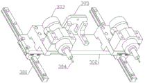
Preferably, the propelling device 307 includes propelling linear guide rails 300, two propelling linear guide rails 300 are respectively arranged on the side surface fixing seats, the propelling fixing seats 301 are arranged on the sliders of the two propelling linear guide rails 300, the front and rear ends of the upper surface of the propelling fixing seats 301 are respectively provided with a first driving module and a second driving module, the first driving module includes a propelling support 302, a propelling motor 303 is arranged in the propelling support 302 in a penetrating manner, a propelling grinding head 304 is arranged on a rotating shaft of the propelling motor 303, a propelling fixing frame 305 is arranged on the rear side of the first driving module, and the second driving module and the first driving module are identical in structure.
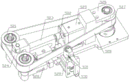
Preferably, the pressing device 308 includes a pressing fixing plate 310, the front and rear ends of the lower surface of the pressing fixing plate 310 are respectively disposed on the two sliders of the pushing linear guide 300, the front and rear ends of the upper surface of the pressing fixing plate 310 are respectively provided with a buffer module, the middle of the pressing fixing plate 310 is provided with a pressing support frame 311, the right side of the pressing support frame 311 is provided with a pressing connection frame 312, the working end of the first pushing cylinder 306 penetrates through the pushing fixing frame 305 to be fixedly connected with the left side of the pressing connection frame 312, the upper side of the pressing connection frame 312 is horizontally provided with a pressing first cylinder 313, the working end of the pressing first cylinder 313 is fixedly connected with the right side of the pushing fixing frame 305, the upper surface of the pressing support frame 311 is vertically penetrated with a pressing second cylinder 314, and the right end of the pressing support frame 311 is vertically and symmetrically provided with pressing guide posts 315, the upper parts of the two downward pressing guide columns 315 are movably provided with downward pressing mounting frames 316, the front ends and the rear ends of the lower surfaces of the downward pressing mounting frames 316 are respectively provided with downward pressing finger cylinders 317, the lower surfaces of the two downward pressing finger cylinders 317 are respectively provided with downward pressing bearing seats, downward pressing rotating shafts 318 are vertically and movably arranged in the circle centers of the downward pressing bearing seats, and the working ends of the two downward pressing finger cylinders 317 are respectively provided with downward pressing clamping jaws 319.
Further, the buffering module is including buffering first module buffering second module, buffering first module is provided with the front end of pushing down fixed plate 310, buffering first module is including buffering fixed plate, the rear end of buffering fixed plate runs through and is provided with the buffer, the front end of buffering fixed plate runs through and is provided with buffering positioning bolt, the buffering second module with the structure of buffering first module is the same.
Preferably, the rotating device 309 includes a rotating fixing seat 320, the front end and the rear end of the lower surface of the rotating fixing seat 320 are respectively vertically provided with a rotating servo motor 321, the left side of the upper surface of the rotating fixing seat 320 is horizontally provided with a rotating linear guide rail 322, the sliders at the front end and the rear end of the rotating linear guide rail 322 are respectively provided with a blade fixing seat 323, the upper surfaces of the two blade fixing seats 323 are respectively provided with a rotating blade 324, the right sides of the front end and the rear end of the rotating linear guide rail 322 are respectively provided with a rotating cylinder 325, the working ends of the two rotating cylinders 325 are respectively fixedly connected with the right side surfaces of the two blade fixing seats 323, the front side and the rear side of the rotating linear guide rail 322 are respectively vertically provided with a rotating bearing seat 326, the circle center of the two rotating bearing seats 326 is provided with a rotating shaft in a penetrating manner, the upper ends of the two rotating shafts are respectively provided with a rotating positioning seat 327 in a penetrating manner, two the lower extreme of rotatory pivot is respectively through rotatory hold-in range and two rotatory servo motor 321's pivot swing joint, the front and back side of rotatory fixing base 320 is provided with rotatory buffering module respectively.
Further, rotatory buffering module is including rotatory first buffering module and rotatory second buffering module, rotatory first buffering module is including rotatory buffering mounting panel, the upper portion level of rotatory buffering mounting panel is run through and is provided with rotatory buffer.
Preferably, the inner hole deburring mechanism 3 comprises an inner hole supporting frame 400, inner hole transplanting devices are respectively arranged on the left side surface and the right side surface of the inner hole supporting frame 400, a first linear sliding table 401 is respectively and horizontally arranged on the rear side surface of the inner hole supporting frame 400, a second linear sliding table 402 is respectively and vertically arranged on the two sliding blocks of the first linear sliding table 401, inner hole fixing seats 403 are respectively arranged on the two sliding blocks of the second linear sliding table 402, inner hole motors 404 are respectively arranged on the two inner hole fixing seats 403 in a penetrating manner, inner hole grinding heads 405 are respectively arranged on the rotating shafts of the two inner hole motors 404, linear positioning devices are horizontally and symmetrically arranged in the inner hole supporting frame 400 and comprise linear first positioning modules and linear second positioning modules, each linear first positioning module comprises a positioning linear sliding table 410, and a positioning linear guide rail 411 is horizontally arranged on the inner side surface of the positioning linear sliding table 410, location sharp slip table 410 with the slip table of location linear guide 411 is improved level and is provided with location fixed plate 412, the symmetry is provided with location finger cylinder 413, two around the upper surface of location fixed plate 412 the work end that location finger cylinder 413 was provided with location clamping jaw 414 respectively, two the clamping jaw inboard is provided with symmetry hole positioning seat 415 around respectively, sharp second location module with the structure of the first location module of straight line is the same.
Further, two hole transplanting device is including transplanting sharp slip table, two be provided with respectively on transplanting sharp slip table's the slider and transplant the mount, two the medial surface of transplanting the mount is provided with perpendicularly respectively and transplants the cylinder, two the work end of transplanting the cylinder level respectively is provided with transplants finger cylinder, two the work end of transplanting finger cylinder is provided with the transplantation clamping jaw respectively.
Preferably, the polishing mechanism 4 comprises a polishing mounting seat 500, a polishing device 501 is arranged on the left side of the polishing mounting seat 500, a polishing device 502 is arranged on the right side of the polishing device 501, a polishing positioning device 503 is arranged on the front side of the polishing fixing seat, the polishing device 501 comprises a polishing fixing frame 510, a first polishing servo motor 511 is arranged on the left side surface of the polishing fixing frame 510, a rotating shaft of the first polishing servo motor 511 penetrates through the middle of the polishing fixing frame 510, a polishing cam is arranged in the middle of the rotating shaft, polishing linear guide rails 512 are respectively and symmetrically arranged on the left side wall and the right side wall in the polishing fixing frame 510, a polishing support 513 is horizontally arranged on a sliding block of the polishing linear guide rails 512, a second polishing servo motor 514 penetrates through the rear end of the polishing support 513, a polishing rotating shaft is movably arranged in the middle of the polishing support 513, the pivot of polishing with the cam of polishing mutually supports, the activity is run through respectively to the front and back side of the pivot of polishing and is provided with the guide post 515 of polishing, and the top level of two guide posts 515 of polishing is provided with the regulation module.
Preferably, the adjusting module comprises an adjusting mounting frame 520, adjusting first wheels 521 are movably arranged at the front end of the adjusting mounting frame 520 in a bilateral symmetry manner, an adjusting linear guide 522 is horizontally arranged in the middle of the adjusting mounting frame 520, an adjusting second mounting frame 523 is arranged on a sliding block of the adjusting linear guide 522, an adjusting second wheel 524 is movably arranged at the front end of the adjusting second mounting frame 523 in a penetrating manner, an adjusting first cylinder 525 is arranged at the rear side of the adjusting linear guide 522, a working end of the adjusting first cylinder 525 is fixedly connected with the rear side surface of the adjusting second mounting frame 523, an adjusting third mounting frame 526 is arranged at the rear side of the adjusting first cylinder 525 in a penetrating manner, an adjusting third wheel 527 is movably arranged at the rear end of the adjusting third mounting frame 526 in a penetrating manner, the adjusting third wheel 527 is arranged on a rotating shaft of the polishing second servo motor 514 in a penetrating manner, and the adjusting third wheel 527 and the two adjusting first wheels 521 are respectively movably connected through an adjusting abrasive belt 528, an adjusting second cylinder 529 is arranged on the right side surface of the adjusting mounting frame 520, an adjusting fourth mounting frame 530 is arranged at the working end of the adjusting second cylinder 529, and an adjusting fourth wheel 531 is movably arranged at the left end of the adjusting fourth mounting frame 530 in a penetrating manner.
Preferably, the grinding and positioning device 503 comprises a grinding and positioning first linear sliding table 540401, a second linear sliding table 541402 for polishing and positioning is horizontally arranged on the sliding block of the first linear sliding table 540401 for polishing and positioning, a polishing positioning fixing seat 542 is arranged on the sliding block of the polishing positioning second linear sliding table 541402, a polishing positioning servo motor 543 is arranged in the polishing positioning fixing seat 542, a rotating shaft of the polishing positioning servo motor 543 penetrates through the top end of the polishing positioning fixing seat 542, a polishing positioning reducer 544 is arranged on the polishing positioning fixing seat 542, a rotating shaft below the polishing positioning reducer 544 is fixedly connected with a rotating shaft of the polishing positioning servo motor 543, a polishing positioning seat 545 is arranged on the rotating shaft above the polishing positioning reducer 544, a polishing positioning finger cylinder 546413 is arranged above the polishing positioning seat 545, the working end of the polishing positioning finger cylinder 546413 is provided with a polishing positioning air claw 547.
Preferably, the blanking mechanism 9 includes a blanking frame body 600, a blanking transfer device 601 is disposed on the blanking frame body 600, a first blanking lifting device is disposed at the left end in the blanking frame body 600, and a second blanking lifting device 603 is disposed at the right side of the first blanking lifting device 602; the first elevating gear 602 of unloading includes lifting module, lifting module includes lift mount 630, the front end of lift mount 630 runs through perpendicularly and is provided with lift servo motor 631, the leading flank of lift mount 630 is provided with lift straight line slip table 632 perpendicularly, lift servo motor 631 through lift hold-in range 633 with lift straight line slip table 632's lower extreme swing joint, the side is provided with lift linear guide 634 respectively perpendicularly about lift straight line slip table 632, lift straight line slip table 632 and two be provided with lift support frame 635 on lift linear guide 634's the slider, the side is provided with the first module of unloading location respectively about lifting module.
Further, the blanking transferring device 601 includes the blanking transferring fixing base 610, the blanking transferring fixing base 610 is horizontally disposed at the front side of the blanking frame body 600, a blanking transferring linear sliding table 611 is horizontally disposed on the blanking transferring fixing base 610, a blanking transferring linear guide 612 is horizontally disposed at the rear side of the blanking transferring linear sliding table 611, blanking transferring mounting frames 613 are disposed on the blanking transferring linear sliding table 611 and the sliders of the blanking transferring linear guide 612, a blanking transferring cylinder 614 is vertically disposed at the rear end of the blanking transferring mounting frames 613 in a penetrating manner, blanking transferring guide pillars 615 are respectively and vertically movably disposed at the front and rear sides of the blanking transferring cylinder 614 in a penetrating manner, a blanking transferring fixing frame 616 is horizontally disposed at the lower ends of the two blanking transferring guide pillars 615, and the working end of the blanking transferring cylinder 614 is fixedly connected to the upper surface of the blanking transferring fixing frame 616, the left side and the right side of the blanking transfer fixing frame 616 are respectively vertically provided with a blanking transfer suction nozzle 617 in a penetrating way.
Preferably, the first module in unloading location includes unloading locating plate 620, unloading locating plate 620 is total two, two the upper and lower end difference level of unloading locating plate 620 trailing flank is provided with unloading location dead lever 621, four the activity is provided with unloading positioning seat 622, four run through respectively to the rear end of unloading location dead lever 621 the unloading positioning seat 622 sets up respectively on the unloading frame body 600, the side is provided with unloading location second module and unloading location third module respectively about the first module in unloading location, unloading location second module with unloading location third module with the structure of the first module in unloading location is the same, the first elevating gear 602 of unloading with the structure of unloading second elevating gear 603 is the same.
Compared with the prior art, the beneficial effects are that, adopt above-mentioned scheme, side deburring mechanism 2 is applicable in anomalous side to the burring of die casting side, hole deburring mechanism 3 makes the aperture precision high to the hole burring of die casting, grinding mechanism 4 makes the work piece more accord with the use quality requirement to the upper and lower face burring of die casting and polish, unloading mechanism 9 can automatic balance unloading, be fit for the continuous production in batches, production safety has been improved, work efficiency and quality have been improved, production cost has effectively been reduced, good market using value has.
Drawings
FIG. 1 is a schematic view of the overall structure of the present invention;
FIG. 2 is a schematic view of a side deburring mechanism of the present invention;
FIG. 3 is a schematic view of a propulsion apparatus of the present invention;
FIG. 4 is a schematic view of a hold-down device of the present invention;
FIG. 5 is a schematic view of a rotary apparatus of the present invention;
FIG. 6 is a schematic view of the inner bore deburring mechanism of the present invention;
FIG. 7 is a schematic view of a grinding mechanism of the present invention;
FIG. 8 is a schematic view of a polishing apparatus of the present invention;
FIG. 9 is a schematic view of a polishing positioning device of the present invention;
FIG. 10 is a schematic view of a conditioning module of the present invention;
FIG. 11 is a schematic view of a blanking mechanism of the present invention;
FIG. 12 is a schematic view of a blanking transfer device according to the present invention;
FIG. 13 is a schematic view of a first lifting device for blanking of the present invention;
FIG. 14 is a schematic view of a lift module according to the present invention;
the reference numbers indicated in the figures: the device comprises a cabinet body 1, a side deburring mechanism 2, an inner hole deburring mechanism 3, a polishing mechanism 4, a first transfer device 5, a chain plate conveyor 6, a second transfer device 7, a third transfer device 8, a blanking mechanism 9, a propelling linear guide rail 300, a propelling fixing seat 301, a propelling support 302, a propelling motor 303, a propelling grinding head 304, a propelling fixing frame 305, a propelling first air cylinder 306, a propelling device 307, a pressing device 308, a rotating device 309, a pressing fixing plate 310, a pressing support 311, a pressing connecting frame 312, a pressing first air cylinder 313, a pressing second air cylinder 314, a pressing guide pillar 315, a pressing mounting frame 316, a pressing finger air cylinder 317, a pressing rotating shaft 318, a pressing clamping claw 319, a rotating fixing seat 320, a rotating servo motor 321, a rotating linear guide rail 322, a blade fixing seat 323, a rotating blade 324, a rotating air cylinder 325, a rotating shaft bearing 326, a rotating positioning seat 327, An inner hole supporting frame 400, a first linear sliding table 401, a second linear sliding table 402, an inner hole fixing seat 403, an inner hole motor 404, an inner hole grinding head 405, a positioning linear sliding table 410, a positioning linear guide rail 411, a positioning fixing plate 412, a positioning finger cylinder 413, a positioning clamping jaw 414, an inner hole positioning seat 415, a grinding mounting seat 500, a grinding device 501, a polishing device 502, a grinding positioning device 503, a grinding fixing frame 510, a first grinding servo motor 511, a grinding linear guide rail 512, a grinding support 513, a second grinding servo motor 514, a grinding guide column 515, an adjusting mounting frame 520, an adjusting first wheel 521, an adjusting linear guide rail 522, an adjusting second mounting frame 523, an adjusting second wheel 524, an adjusting first cylinder 525, an adjusting third mounting frame 526, an adjusting third wheel 527, an adjusting abrasive belt 528, an adjusting second cylinder 529, an adjusting fourth mounting frame 530, an adjusting fourth wheel 531, a grinding positioning first linear sliding table 540, an adjusting fourth wheel 531, a grinding positioning, The blanking device comprises a second polishing and positioning linear sliding table 541, a polishing and positioning fixing seat 542, a polishing and positioning servo motor 543, a polishing and positioning speed reducer 544, a polishing positioning seat 545, a polishing and positioning finger cylinder 546, a polishing and positioning gas claw 547, a blanking frame body 600, a blanking transfer device 601, a blanking first lifting device 602, a blanking second lifting device 603, a blanking transfer fixing seat 610, a blanking transfer linear sliding table 611, a blanking transfer linear guide rail 612, a blanking transfer mounting frame 613, a blanking transfer cylinder 614, a blanking transfer guide pillar 615, a blanking transfer fixing frame 616, a blanking transfer suction nozzle 617, a blanking positioning plate 620, a blanking positioning fixing rod 621, a blanking positioning seat 622, a lifting fixing frame 630, a lifting servo motor 631, a lifting linear sliding table 632, a lifting synchronous belt 633, a lifting linear guide rail 634 and a lifting support frame 635.
Detailed Description
In order to facilitate an understanding of the invention, the invention is described in more detail below with reference to the accompanying drawings and specific examples. Preferred embodiments of the present invention are shown in the drawings. This invention may, however, be embodied in many different forms and should not be construed as limited to the embodiments set forth herein. Rather, these embodiments are provided so that this disclosure will be thorough and complete.
It will be understood that when an element is referred to as being "secured to" another element, it can be directly on the other element or intervening elements may also be present. When an element is referred to as being "connected" to another element, it can be directly connected to the other element or intervening elements may also be present. The terms "vertical," "horizontal," "left," "right," "front," "rear," and the like as used herein are for descriptive purposes only.
Unless defined otherwise, all technical and scientific terms used herein have the same meaning as commonly understood by one of ordinary skill in the art to which this invention belongs. The terminology used in the description of the invention herein is for the purpose of describing particular embodiments only and is not intended to be limiting of the invention.
Preferably, as shown in fig. 1, the full-automatic deburring equipment for die castings comprises a cabinet body 1, a side deburring mechanism 2, an inner hole deburring mechanism 3 and a grinding mechanism 4 are sequentially arranged on the upper surface in the cabinet body 1 from left to right, the side deburring mechanism 2 comprises a side fixing seat, a first pushing cylinder 306 is arranged at the left end of the upper surface of the side fixing seat, a pushing device 307 is arranged on the right side of the first pushing cylinder 306, a pressing device 308 is arranged on the right side of the pushing device 307, a rotating device 309 is arranged on the right side of the pressing device 308, a first transfer device 5 is arranged on the front side of the side deburring mechanism 2, a chain plate conveyor 6 is arranged on the front side of the first transfer device 5, a second transfer device 7 is arranged at the right end of the chain plate conveyor 6, a third transfer device 8 is arranged on the right side of the second transfer device 7, the front side of the third transfer device 8 is provided with the blanking mechanism 9, so that the blanking mechanism is suitable for continuous mass production, the labor intensity of workers is reduced, the working efficiency and quality are improved, and the cost is effectively reduced.
Preferably, as shown in fig. 2 to 5, in order to adapt to the precise deburring of the side surface irregularity of the die casting, a side deburring mechanism 2 is provided, when the die casting is placed on a rotary positioning seat 327, a first air cylinder 306 is pushed to push a pressing device 308 to move rightwards, a pressing second air cylinder 314 drives a pressing mounting bracket 316 to descend, the pressing mounting bracket 316 descends and simultaneously drives two pressing finger cylinders 317 to move downwards, so that the two pressing rotating shafts 318 penetrate through the inner hole of the die casting, the die casting does not shift during rotation, the deburring is more accurate, the two pressing finger cylinders 317 contract to drive the pressing clamping jaws 319 to tightly clamp the die casting,
meanwhile, the first air cylinder 313 is pressed downwards to contract to drive the propulsion device 307 to move rightwards, the propulsion motor 303 in the propulsion device 307 rotates to drive the propulsion grinding head 304 to rotate, so that the two propulsion grinding heads 304 remove burrs on the side surfaces of the die castings, after the deburring is completed, the pressing clamping jaws 319 are loosened, then the two rotary servo motors 321 rotate to drive the rotary shafts in the two rotary shaft seats 326 to rotate, then the two rotary shafts drive the two rotary positioning seats 327 to rotate, the two rotary positioning seats 327 rotate to drive the die castings to rotate, after the deburring is completed, the pressing clamping jaws 319 clamp the die castings, and the propulsion grinding head 304 removes burrs,
meanwhile, the two rotary cylinders 325 contract to drive the rotary blades 324 to remove burrs in the side sliding grooves of the die castings, the first cylinder 313 is pressed downwards to stretch and drive the pushing device 307 to move left and right, and finally accurate burr removal effect on the uneven side surfaces of the die castings is achieved.
Preferably, as shown in fig. 6, in order to solve the problem that the inner hole of the die casting is difficult to process and the deburring efficiency is low, an inner hole deburring mechanism 3 is provided, two transplanting linear sliding tables drive two transplanting cylinders to move forwards respectively, when the transplanting linear sliding tables reach the upper surface of a chain conveyor 6, the two transplanting cylinders push and drive the two transplanting finger cylinders to descend respectively, when the transplanting linear sliding tables reach the die casting, the two transplanting finger cylinders shrink respectively to drive the transplanting clamping jaws to clamp the die casting, then the two transplanting linear sliding tables slide to drive the two transplanting clamping jaws to move backwards respectively, the die casting is placed on an inner hole positioning seat 415 one by one, when the die casting is fully placed, the positioning clamping jaw 414 shrinks to drive the positioning clamping jaw 414 to tightly clamp the die casting, the two positioning linear sliding tables 410 drive the inner hole positioning seat 415 to move forwards and backwards respectively, the two first linear sliding tables 401 drive the inner hole grinding head 405 to move leftwards and rightwards respectively, the two second linear sliding tables 402 respectively drive the inner hole grinding heads 405 to move up and down, and finally three-dimensional movement is achieved, so that the two inner hole grinding heads 405 can accurately remove burrs of the inner holes of the die castings one by one.
Preferably, as shown in fig. 7 to 10, in order to remove burrs on the upper surface and the lower surface of the die casting and make the die casting more consistent with the use quality requirements, a grinding mechanism 4 is provided, when the die casting is placed in the grinding positioning gas claw 547, the grinding positioning finger cylinder 546413 is contracted to drive the grinding positioning gas claw 547 to clamp the die casting, the grinding positioning first linear sliding table 540401 slides to drive the grinding positioning second linear sliding table 541402 to move leftwards, the grinding positioning second linear sliding table 541402 slides to drive the grinding positioning gas claw 547 to move backwards, so that one surface of the die casting moves towards an adjusting abrasive belt 528 in the grinding device 501,
meanwhile, the second grinding servo motor 514 rotates to drive the third adjusting wheel 527 to rotate, the third adjusting wheel 527 rotates to drive the adjusting abrasive belt 528 to rotate in the grooves of the two first adjusting wheels 521, the first adjusting cylinder 525 pushes the second adjusting mounting rack 523 to move forwards, the second adjusting wheel 524 which adjusts the front end of the second mounting rack 523 supports the adjusting abrasive belt 528, so that the adjusting abrasive belt 528 has supporting force during grinding and cannot be broken due to excessive pressure, meanwhile, the second adjusting cylinder 529 is adjusted to stretch and drive the fourth adjusting wheel 531 to move left and right to adjust the tension of the adjusting abrasive belt 528, the adjusting abrasive belt 528 is always in an optimal working state, the adjusting abrasive belt 528 is prevented from being broken due to excessive loosening and deflection or excessive tightening, the first grinding servo motor 511 rotates to drive the grinding cam to rotate, the convex part jacks up the grinding rotating shaft when the grinding cam rotates, and the grinding rotating shaft drives the grinding support 513 to move upwards on the four grinding linear guide rails 512, the support 513 of polishing drives the regulation module and reciprocates when reciprocating, realize that the regulation module can reciprocate deburring to the die casting, accomplish the back, location servo motor 543 of polishing rotates and drives location reduction gear 544 of polishing and rotate, location reduction gear 544 of polishing drives location gas claw 547 rotation of polishing when pivoted, make the die casting rotation carry out another side and polish the deburring, after accomplishing, the first straight line slip table 540401 of location of polishing slides and drives location gas claw 547 of polishing and remove right, make the die casting on the location gas claw 547 of polishing remove burnishing device 502, the same mode carries out the two sides and more carefully polishes the polishing and handles.
Preferably, as shown in fig. 11 to 14, in order to make the castings automatically fed in order, a feeding mechanism 9 is provided, a tray is placed on the lifting support 635 in the second feeding device 603, the lifting servo motor 631 rotates to drive the lifting linear sliding table 632 to ascend, the lifting linear sliding table 632 drives the lifting support 635 to ascend on the two lifting linear guide rails 634 while ascending, when the lifting support 635 ascends to the top, the feeding transfer cylinder 614 pushes the feeding transfer fixing frame 616 to descend, the feeding transfer fixing frame 616 drives the feeding transfer nozzle 617 to move to the tray while descending, and sucks up the tray, the feeding transfer linear sliding table 611 drives the feeding transfer mounting frame 613 to move to the left, the feeding transfer mounting frame 613 drives the feeding transfer nozzle 617 to move, when the pallet moves to the lifting support 635 in the first feeding device, the feeding transfer nozzle 617 is loosened, make the tray put into lift support 635 on, wait for the die casting to put into the tray one by one, when one deck tray was full, lift servo motor 631 among the first elevating gear of unloading rotates and drives lift support 635 and descend a check, can adjust the position that the distance of unloading location dead lever 621 changed unloading locating plate 620, adjust the tray that adapts to equidimension not, the position when unloading locating plate 620 is used for fixing a position the tray oscilaltion, the balance of reinforcing tray is stable.
The working principle of the invention is as follows: the die castings are conveyed to the working range of a first transfer device through a chain plate conveyor, the die castings are clamped by the first transfer device and then are placed on a rotary positioning seat in a side deburring mechanism one by one, burrs are removed from the side surfaces of the die castings by the side deburring mechanism, the die castings are taken out and placed in the chain plate conveyor one by the first transfer device after the die castings are clamped by the first transfer device, the die castings are conveyed to the working range of an inner hole deburring mechanism by the chain plate conveyor, the die castings are clamped by two inner hole transplanting devices one by one and then are placed in an inner hole positioning seat, burrs are removed from inner holes of the die castings by the inner hole deburring mechanism, the die castings are taken out and placed in the chain plate conveyor one by one after the die castings are clamped by the two inner hole transplanting devices, the die castings are conveyed to the working range of a second transfer device by the chain plate conveyor, and the die castings are placed in a polishing positioning air claw after the die castings are clamped by the second transfer device, clamping back grinding positioning device removes grinding device and carries out the deburring of polishing for the first time, polishing device carries out thinner polishing and polishing for the second time after accomplishing, grinding positioning device removes the die casting in second transfer device working range after accomplishing, put into the drag chain conveyor after having second transfer device to press from both sides, drag chain conveyor is in carrying the die casting to third transfer device working range, third transfer device is in putting into the tray on the lift support frame in the unloading mechanism after pressing from both sides the die casting clamp, then wait the manual work and take away.
The technical features mentioned above are combined with each other to form various embodiments which are not listed above, and all of them are regarded as the scope of the present invention described in the specification; also, modifications and variations may be suggested to those skilled in the art in light of the above teachings, and it is intended to cover all such modifications and variations as fall within the true spirit and scope of the invention as defined by the appended claims.
Claims (10)
1. The full-automatic deburring equipment for die castings is characterized by comprising a cabinet body, wherein a side deburring mechanism, an inner hole deburring mechanism and a polishing mechanism are sequentially arranged on the upper surface in the cabinet body from left to right, the side deburring mechanism comprises a side fixed seat, a first pushing cylinder is arranged at the left end of the upper surface of the side fixed seat, a propelling device is arranged on the right side of the first pushing cylinder, a pressing device is arranged on the right side of the propelling device, the right side of the pressing device is provided with a rotating device, the front side of the side deburring mechanism is provided with a first transfer device, a chain plate conveyor is arranged at the front side of the first transfer device, a second transfer device is arranged at the right end of the chain plate conveyor, and a third transfer device is arranged on the right side of the second transfer device, and a blanking mechanism is arranged on the front side of the third transfer device.
2. The full-automatic deburring equipment for die castings according to claim 1, characterized in that the propelling device comprises two propelling linear guide rails, the two propelling linear guide rails are respectively arranged on the side fixing seats, the propelling fixing seats are arranged on the sliding blocks of the two propelling linear guide rails, a first driving module and a second driving module are respectively arranged at the front end and the rear end of the upper surface of each propelling fixing seat, the first driving module comprises a propelling support, a propelling motor penetrates through the propelling support, a propelling grinding head is arranged on a rotating shaft of the propelling motor, a propelling fixing frame is arranged at the rear side of the first driving module, and the second driving module and the first driving module are identical in structure.
3. The full-automatic deburring equipment for die castings according to claim 1, characterized in that the pressing device comprises a pressing fixing plate, the front end and the rear end of the lower surface of the pressing fixing plate are respectively arranged on the sliding blocks of the two pushing linear guide rails, the front end and the rear end of the upper surface of the pressing fixing plate are respectively provided with a buffer module, the middle part of the pressing fixing plate is provided with a pressing support frame, the right side surface of the pressing support frame is provided with a pressing connecting frame, the working end of the pushing first cylinder penetrates through the pushing fixing frame and is fixedly connected with the left side surface of the pressing connecting frame, the upper side of the pressing connecting frame is horizontally provided with a pressing first cylinder, the working end of the pressing first cylinder is fixedly connected with the right side surface of the pushing fixing frame, the upper surface of the pressing support frame is vertically penetrated and provided with a pressing second cylinder, the right-hand member of push down the support frame is perpendicular the symmetry and is provided with the push down guide pillar, two the upper portion activity of push down the guide pillar is provided with the push down mounting bracket, the front and back end of push down mounting bracket lower surface is provided with respectively pushes down the finger cylinder, and the lower surface of two push down finger cylinders is provided with respectively pushes down the bearing frame, the perpendicular activity is provided with the pivot of pushing down in the centre of a circle of pushing down the bearing frame, two the work end of pushing down the finger cylinder is provided with respectively and pushes down the clamping jaw.
4. The full-automatic deburring equipment for die castings according to claim 1, characterized in that the rotating device comprises rotating fixed seats, the front and rear ends of the lower surface of each rotating fixed seat are respectively vertically provided with a rotating servo motor, the left side edge of the upper surface of each rotating fixed seat is horizontally provided with a rotating linear guide rail, the sliding blocks at the front and rear ends of each rotating linear guide rail are respectively provided with a blade fixed seat, the upper surfaces of the two blade fixed seats are respectively provided with a rotating blade, the right sides of the front and rear ends of each rotating linear guide rail are respectively provided with a rotating cylinder, the working ends of the two rotating cylinders are respectively fixedly connected with the right side surfaces of the two blade fixed seats, the front and rear sides of each rotating linear guide rail are respectively vertically provided with a rotating bearing seat, the circle centers of the two rotating bearing seats are provided with a rotating shaft in a penetrating way, and the upper ends of the two rotating shafts are respectively provided with a rotating positioning seat in a penetrating way, two the lower extreme of rotatory pivot is respectively through rotatory hold-in range and two rotatory servo motor's pivot swing joint, the front and back side of rotatory fixing base is provided with rotatory buffering module respectively.
5. The die casting full-automatic deburring equipment as claimed in claim 1, characterized in that the inner hole deburring mechanism comprises an inner hole support frame, inner hole transplanting devices are respectively arranged on the left side surface and the right side surface of the inner hole support frame, first linear sliding tables are respectively and horizontally arranged on the rear side surface of the inner hole support frame, second linear sliding tables are respectively and vertically arranged on the sliding blocks of the two first linear sliding tables, inner hole fixing seats are respectively arranged on the sliding blocks of the two second linear sliding tables, inner hole motors are respectively arranged on the two inner hole fixing seats in a penetrating manner, inner hole grinding heads are respectively arranged on the rotating shafts of the two inner hole motors, linear positioning devices are horizontally and symmetrically arranged in the inner hole support frame and comprise linear first positioning modules and linear second positioning modules, each linear first positioning module comprises a positioning linear sliding table, the inboard level of location sharp slip table is provided with location linear guide, location sharp slip table with location linear guide's slip table improved level is provided with the location fixed plate, the symmetry is provided with location finger cylinder, two around the upper surface of location fixed plate the work end of location finger cylinder is provided with the location clamping jaw respectively, two the clamping jaw inboard is provided with symmetry hole positioning seat around respectively, sharp second location module with the structure of the first location module of straight line is the same.
6. The full-automatic deburring equipment for die castings according to claim 1, characterized in that the grinding mechanism comprises a grinding mounting seat, a grinding device is arranged on the left side above the grinding mounting seat, a polishing device is arranged on the right side of the grinding device, a grinding positioning device is arranged on the front side of the grinding fixing seat, the grinding device comprises a grinding fixing frame, a grinding first servo motor is arranged on the left side surface of the grinding fixing frame, a rotating shaft of the grinding first servo motor penetrates through the middle of the grinding fixing frame, a grinding cam is arranged in the middle of the rotating shaft, grinding linear guide rails are respectively and vertically and symmetrically arranged on the left side wall and the right side wall in the grinding fixing frame, a grinding support is horizontally arranged on a sliding block of the four grinding linear guide rails, and a grinding second servo motor penetrates through the rear end of the grinding support, the middle part of the polishing support is penetrated through the activity and is provided with the pivot of polishing, polish the pivot with the cam of polishing is mutually supported, the activity is penetrated respectively to the front and back side of the pivot of polishing and is provided with the guide post of polishing, and the top level of two guide posts of polishing is provided with the regulation module.
7. The full-automatic deburring equipment for die castings according to claim 6, characterized in that the adjusting module comprises an adjusting mounting frame, the front end of the adjusting mounting frame is provided with a first adjusting wheel in a bilateral symmetry manner, the middle part of the adjusting mounting frame is horizontally provided with an adjusting linear guide rail, a second adjusting mounting frame is arranged on a sliding block of the adjusting linear guide rail, the front end of the second adjusting mounting frame is movably provided with a second adjusting wheel in a penetrating manner, the rear side of the adjusting linear guide rail is provided with a first adjusting cylinder, the working end of the first adjusting cylinder is fixedly connected with the rear side surface of the second adjusting mounting frame, the rear side of the first adjusting cylinder is provided with a third adjusting mounting frame, the rear end of the third adjusting mounting frame is movably provided with a third adjusting wheel in a penetrating manner, and the third adjusting wheel is arranged on a rotating shaft of the second grinding servo motor in a penetrating manner, the adjusting third wheel and the two adjusting first wheels are movably connected through an adjusting abrasive belt respectively, an adjusting second cylinder is arranged on the right side of the adjusting mounting frame, an adjusting fourth mounting frame is arranged at the working end of the adjusting second cylinder, and an adjusting fourth wheel is movably arranged at the left end of the adjusting fourth mounting frame in a penetrating mode.
8. The die casting full-automatic deburring equipment as claimed in claim 6, wherein the polishing positioning device comprises a polishing positioning first linear sliding table, a polishing positioning second linear sliding table is horizontally arranged on a sliding block of the polishing positioning first linear sliding table, a polishing positioning fixing seat is arranged on a sliding block of the polishing positioning second linear sliding table, a polishing positioning servo motor is arranged in the polishing positioning fixing seat, a rotating shaft of the polishing positioning servo motor penetrates through the top end of the polishing positioning fixing seat, a polishing positioning reducer is arranged on the polishing positioning fixing seat, a rotating shaft below the polishing positioning reducer is fixedly connected with a rotating shaft of the polishing positioning servo motor, a polishing positioning seat is arranged on the rotating shaft above the polishing positioning reducer, a polishing positioning finger cylinder is arranged on the polishing positioning seat, and the working end of the polishing positioning finger cylinder is provided with a polishing positioning air claw.
9. The full-automatic deburring equipment for die castings according to claim 1, wherein the blanking mechanism comprises a blanking frame body, a blanking transfer device is arranged on the blanking frame body, a blanking first lifting device is arranged at the left end in the blanking frame body, and a blanking second lifting device is arranged at the right side of the blanking first lifting device; the first unloading lifting device comprises a lifting module, the lifting module comprises a lifting fixing frame, a lifting servo motor is arranged at the front end of the lifting fixing frame in a perpendicular penetrating mode, a lifting linear sliding table is arranged on the front side face of the lifting fixing frame in a perpendicular penetrating mode, the lifting servo motor is movably connected with the lower end of the lifting linear sliding table through a lifting synchronous belt, a lifting linear guide rail is arranged on the left side and the right side of the lifting linear sliding table in a perpendicular mode respectively, the lifting linear sliding table and the lifting linear sliding table are provided with lifting support frames on sliders of the lifting linear guide rail, and the first unloading positioning module is arranged on the left side and the right side of the lifting module respectively.
10. The full-automatic deburring equipment for die castings according to claim 9, wherein the first blanking positioning module comprises two blanking positioning plates, the two blanking positioning plates are horizontally provided with blanking positioning fixing rods at the upper and lower ends of the rear side surfaces of the two blanking positioning plates respectively, the rear ends of the four blanking positioning fixing rods are movably provided with blanking positioning seats respectively in a penetrating manner, the four blanking positioning seats are respectively arranged on the blanking frame body, a second blanking positioning module and a third blanking positioning module are respectively arranged at the left and right sides of the first blanking positioning module, the second blanking positioning module and the third blanking positioning module are identical in structure to the first blanking positioning module, and the first blanking lifting device and the second blanking lifting device are identical in structure.
Priority Applications (1)
| Application Number | Priority Date | Filing Date | Title |
|---|---|---|---|
| CN202111241260.4A CN113910045A (en) | 2021-10-25 | 2021-10-25 | Full-automatic deburring equipment for die castings |
Applications Claiming Priority (1)
| Application Number | Priority Date | Filing Date | Title |
|---|---|---|---|
| CN202111241260.4A CN113910045A (en) | 2021-10-25 | 2021-10-25 | Full-automatic deburring equipment for die castings |
Publications (1)
| Publication Number | Publication Date |
|---|---|
| CN113910045A true CN113910045A (en) | 2022-01-11 |
Family
ID=79242932
Family Applications (1)
| Application Number | Title | Priority Date | Filing Date |
|---|---|---|---|
| CN202111241260.4A Withdrawn CN113910045A (en) | 2021-10-25 | 2021-10-25 | Full-automatic deburring equipment for die castings |
Country Status (1)
| Country | Link |
|---|---|
| CN (1) | CN113910045A (en) |
Cited By (1)
| Publication number | Priority date | Publication date | Assignee | Title |
|---|---|---|---|---|
| CN114800261A (en) * | 2022-04-14 | 2022-07-29 | 深圳市德治鑫自动化设备有限公司 | Unloading equipment in medium plate burring multistation |
-
2021
- 2021-10-25 CN CN202111241260.4A patent/CN113910045A/en not_active Withdrawn
Cited By (1)
| Publication number | Priority date | Publication date | Assignee | Title |
|---|---|---|---|---|
| CN114800261A (en) * | 2022-04-14 | 2022-07-29 | 深圳市德治鑫自动化设备有限公司 | Unloading equipment in medium plate burring multistation |
Similar Documents
| Publication | Publication Date | Title |
|---|---|---|
| CN202006360U (en) | Automatic metal post assembly device for hard disk drive frame | |
| CN210649927U (en) | Dull and stereotyped foundry goods grinding device | |
| CN112122593A (en) | Automatic production line for aluminum alloy castings | |
| CN113910045A (en) | Full-automatic deburring equipment for die castings | |
| CN105750658A (en) | Fully automatic numerical control chamfering machine | |
| CN112179570A (en) | Sand falling, cutting and shot blasting air tightness detection mechanism of aluminum alloy casting production line | |
| CN216917358U (en) | Jacking positioning mechanism for speed chain assembly line | |
| CN212822711U (en) | Automatic turnover mechanism for high-speed lathe | |
| CN113977276A (en) | Automatic constitution cutting equipment of production spare after die-casting | |
| CN112171211A (en) | Automatic production process of aluminum alloy casting | |
| CN217168233U (en) | Irregular casting clamping device for casting production | |
| CN214723221U (en) | Cutting mechanical equipment for industrial processing | |
| CN205600061U (en) | Full -automatic numerical control beveler | |
| CN112847028A (en) | Surface treatment equipment for machining automobile casting parts | |
| CN211709308U (en) | Reciprocating robot and integrated surface grinding system | |
| CN112571056A (en) | Automatic workstation of flexible robot | |
| CN213615475U (en) | Machining device for metal casting | |
| CN113510596B (en) | Feeding mechanism of polishing machine for bolt machining | |
| CN219504543U (en) | Precision machining platform | |
| CN218425977U (en) | Sawing machine capable of automatically positioning and pushing material | |
| CN219005604U (en) | Polishing and transplanting mechanism | |
| CN220762132U (en) | Automatic grinding device of foundry goods | |
| CN220560574U (en) | Fixing device convenient for polishing saw teeth | |
| CN218592398U (en) | Machining center carrier | |
| CN220330125U (en) | Fixing device of linear guide connecting plate for metal cutting |
Legal Events
| Date | Code | Title | Description |
|---|---|---|---|
| PB01 | Publication | ||
| PB01 | Publication | ||
| SE01 | Entry into force of request for substantive examination | ||
| SE01 | Entry into force of request for substantive examination | ||
| WW01 | Invention patent application withdrawn after publication |
Application publication date: 20220111 |
|
| WW01 | Invention patent application withdrawn after publication |