CN1138306A - Process and device for producing a three-diamensional object - Google Patents
Process and device for producing a three-diamensional object Download PDFInfo
- Publication number
- CN1138306A CN1138306A CN95191132A CN95191132A CN1138306A CN 1138306 A CN1138306 A CN 1138306A CN 95191132 A CN95191132 A CN 95191132A CN 95191132 A CN95191132 A CN 95191132A CN 1138306 A CN1138306 A CN 1138306A
- Authority
- CN
- China
- Prior art keywords
- layer
- otch
- radiation
- workbench
- chamber wall
- Prior art date
- Legal status (The legal status is an assumption and is not a legal conclusion. Google has not performed a legal analysis and makes no representation as to the accuracy of the status listed.)
- Pending
Links
Images

Classifications
-
- B—PERFORMING OPERATIONS; TRANSPORTING
- B23—MACHINE TOOLS; METAL-WORKING NOT OTHERWISE PROVIDED FOR
- B23K—SOLDERING OR UNSOLDERING; WELDING; CLADDING OR PLATING BY SOLDERING OR WELDING; CUTTING BY APPLYING HEAT LOCALLY, e.g. FLAME CUTTING; WORKING BY LASER BEAM
- B23K26/00—Working by laser beam, e.g. welding, cutting or boring
- B23K26/34—Laser welding for purposes other than joining
-
- B—PERFORMING OPERATIONS; TRANSPORTING
- B29—WORKING OF PLASTICS; WORKING OF SUBSTANCES IN A PLASTIC STATE IN GENERAL
- B29C—SHAPING OR JOINING OF PLASTICS; SHAPING OF MATERIAL IN A PLASTIC STATE, NOT OTHERWISE PROVIDED FOR; AFTER-TREATMENT OF THE SHAPED PRODUCTS, e.g. REPAIRING
- B29C67/00—Shaping techniques not covered by groups B29C39/00 - B29C65/00, B29C70/00 or B29C73/00
-
- B—PERFORMING OPERATIONS; TRANSPORTING
- B23—MACHINE TOOLS; METAL-WORKING NOT OTHERWISE PROVIDED FOR
- B23K—SOLDERING OR UNSOLDERING; WELDING; CLADDING OR PLATING BY SOLDERING OR WELDING; CUTTING BY APPLYING HEAT LOCALLY, e.g. FLAME CUTTING; WORKING BY LASER BEAM
- B23K26/00—Working by laser beam, e.g. welding, cutting or boring
- B23K26/08—Devices involving relative movement between laser beam and workpiece
- B23K26/083—Devices involving movement of the workpiece in at least one axial direction
- B23K26/0838—Devices involving movement of the workpiece in at least one axial direction by using an endless conveyor belt
-
- B—PERFORMING OPERATIONS; TRANSPORTING
- B29—WORKING OF PLASTICS; WORKING OF SUBSTANCES IN A PLASTIC STATE IN GENERAL
- B29C—SHAPING OR JOINING OF PLASTICS; SHAPING OF MATERIAL IN A PLASTIC STATE, NOT OTHERWISE PROVIDED FOR; AFTER-TREATMENT OF THE SHAPED PRODUCTS, e.g. REPAIRING
- B29C64/00—Additive manufacturing, i.e. manufacturing of three-dimensional [3D] objects by additive deposition, additive agglomeration or additive layering, e.g. by 3D printing, stereolithography or selective laser sintering
- B29C64/10—Processes of additive manufacturing
- B29C64/141—Processes of additive manufacturing using only solid materials
- B29C64/153—Processes of additive manufacturing using only solid materials using layers of powder being selectively joined, e.g. by selective laser sintering or melting
Abstract
A process is proposed for producing a three-dimensional object. The object in question is built up in layers by the application of successive layers of a material which can be hardened by irradiation with electromagnetic radiation, after which the material is hardened with the object by irradiation at the sites corresponding to the object, so that a container wall (15) for the material (13) is produced.
Description
The present invention relates to method one a wherein said object that generates three-dimensional body and be generate by the equivalent layer layering of input material 13, described material layer can solidify by electromagnetic radiation or particle radiation, after this by material layer being solidified to carry out radiation corresponding to the position of the material of object, thereby and the zone that this moment, material surrounded object is to solidify simultaneously to generate one and be used for this container of material wall; The invention still further relates to one be used to finish said method device one it comprise an adjustable for height support, one puts into the device that is used to solidify on the support 9 with the layer of material, and a radiation appliance and being used to is controlled this radiation appliance and made it to be radiated corresponding to the control device on the layer of the position of object.
This method and apparatus is open at DE 43 00 478 C1.As shown in Figure 1, known devices comprises a substantially horizontal workbench 1, the hole of otch 2 forms that this workbench 1 has.The maximum cross section that this otch 2 compares the object 3 that is generated is big.On workbench 1, there is a radiation appliance 4 also can produce a focused beam 5 as laser instrument.This focused beam 5 is by an arrangement for deflecting 6 deflections and deflected beam 7 is shone on the plane of workbench 1.The described arrangement for deflecting 6 of one control device 8 control, thus light beams deflected 7 can be shone in the working region of being determined by otch 2 on any desired position.
Be arranged with the support 9 of the level that is essentially equally of platform-like at otch 2.This holder device 9 can move between an extreme higher position and extreme lower position along the direction of arrow 11, when described extreme higher position, the surface of support 9 be positioned at otch 2 and basically with the flush of workbench 1, and when described extreme lower position, the distance between support and workbench is greater than the maximum height of object 3.The mobile of above-mentioned support 9 finished by an elevate a turnable ladder positioner 10.
The charging device 12 that applies 13 layers of dusty materials can move transverse to workbench 1 and otch 2 in the horizontal direction, and above-mentioned dusty material 13 can solidify under electromagnetic radiation.For example, this charging device 12 can be a reservoir, has one on it and is used to the scraping brushing device that makes material layer level and smooth.
In known laser sintering processes, at first thereby elevate a turnable ladder positioner 10 moves on to its highest position with holder device 9 and makes the surface of support 9 and the flush of workbench 1, this support one segment distance then descends, this segment distance is corresponding to the desired thickness of first material layer, thereby form a zone that descends in otch 2, the regional side of this decline is to be surrounded by support 9 surfaces by the wall of otch 2 and bottom surface.In the zone of above-mentioned decline, the ground floor by charging device 12 injection material 13 in the vallecular cavity that is formed by otch 2 and support 9 also makes it level and smooth.After this, control device 14 control arrangements for deflecting 6 light beams deflected 7 are shone on the position for the treatment of cured layer, and the material at this place is carried out sintering, and this control are to carry out according to the coordinate data that is stored in the object 3 in the control device 14.Then, sintering is carried out with the material layer to this place in the zone that control device 14 only shines light beams deflected and is adjacent to the material layer of wall within the otch 2, has generated one first annular parietal layer thus, and this annular parietal layer has surrounded the remaining dusty material in the layer fully.
In following step, support 9 is descended continue the thickness of layer, its operation is identical with the operation of the first step.When producing each object layer by sintering one annular parietal layer again on annular parietal layer, thereby can generate the annular wall region 15 of a formation one chamber wall, this chamber wall encases object 3 and remaining unsintered material 13, when support 9 being dropped to workbench 1 when following, can prevent that material 13 from leaking.Repeat above-mentioned steps until generating object 3.
The chamber wall 15 of Gu Huaing remaines in uncured powder 13 wherein simultaneously.Therefore, uncured powder as on the continue supporting of layer.If except columniform chamber wall 15 has solidified, its end and lid have also been solidified, then can avoid in laser sintering device generating object required long cool time, reason is the object that generates can be taken out to put to another independent place from this device together with its container to go to cool off.
Yet above-mentioned known method has following defective.This chamber wall 15 is an independent element, needs it is carried out layered radiation.Therefore the rise time of object will be elongated.Usually, laser beam focus on edge, that is also weaken in the zone of curing vessel wall.So it is difficult wanting to form reliably a stable chamber wall.
Further defective is: the chamber wall that generates during by each layer of laser curing object can hinder the motion of scraping brushing device 12, this scraping brushing device is when every layer of wiper surperficial, can apply certain pressure to each surface, thereby in each generative process, may damage the said vesse wall.
In addition, during as the material that solidifies, can not use above-mentioned known method with molding sand.Reason is and can not generates a not only thin but also sufficiently stable chamber wall with bombardment with laser beams.
The purpose of this invention is to provide a kind of method and device that is used to generate three-dimensional body, it can generate stable chamber wall and object at short notice.
Can achieve the above object according to the method for claim 1 or 21 with according to the device of claim 17 or 25.
Further description can be referring to dependent claims.
The advantage of this method is to save the time of radiation chamber wall or frame, thereby has saved more time.This method is particularly suited for adopting molding sand to do curing materials.
In conjunction with the accompanying drawings, by learning further characteristics of the present invention and advantage to the description of embodiment.
Fig. 1 has schematically illustrated the existing device cutaway view by laser sintered generation three-dimensional body; And
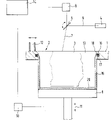
Fig. 2 has then schematically illustrated the cutaway view of an embodiment of apparatus of the present invention of carrying out described object production method.
As shown in Figure 2, this device that is used to finish said method comprises and device components identical shown in Figure 1.Therefore the element that has same numeral no longer is repeated in this description.
This device is also additional to comprise a heating ring 16, and for example this heating ring 16 can form heater coil, and it is arranged in the groove 7 that forms on the wall 18 of workbench 1, and described workbench 1 is provided with otch 2.Heater coil 16 is installed in the groove 17 and its end aligns with wall 18.Groove 17 on the workbench 1 is not the below that just is positioned at working face, (position of this working face depends on that the luminous point of laser beam 7 is the surface of material 13) but be positioned at several centimeters under the working face.In this device, support 9 can be heated, and therefore the ground floor material 13 that adds on the support 9 can solidify under heat effect respectively.
In existent method, support 9 at first moves to its uppermost position in fig-ure by an elevate a turnable ladder positioner 10, this moment the surface of support 9 and the flush of workbench 1, the displacement corresponding to the first material layer desired thickness that descends then, the field side that has formed the zone that descends and this decline this moment in otch 2 are surrounded with the bottom surface by the wall 18 of otch 2 and are limited by the surperficial of support 9.Therefore, ground floor sintered powder material is injected into the thickness of layer extremely predetermined in the zone of the decline of being determined by otch 2 and support 9 by charging device 12 as the molding sand of being made up of band phenolic resin coating silica sand.
Unlike the prior art, thus the ground floor of injection is sintered support 9 heating and under heat effect, solidifies.In this mode, at first form a solid-state bottom 20.Solidify temperature required between 80 ℃ to 160 ℃, with material relevant.
Second step was to make support 9 drop to few displacement corresponding to a layer thickness by control device 14 by elevate a turnable ladder positioner 10, and was injected into few amount corresponding to the required molding sand of a layer thickness and it is smooth in the formed decline zone by charging device 12 in otch 2.Therefore, on solid-state bottom 20, has the uncured material of one deck 13 at least.
After support has descended displacement corresponding to second layer thickness, inject and planarizing material 13 object 3 that can begin to produce this moment.For this reason, thereby control device 14 control arrangements for deflecting 6 make light beams deflected 7 shine the position of these layers that need solidify, and the described layer that needs to solidify is corresponding to the coordinate that is stored in the object 3 in the control device 14.
When reducing support 9,, then surround the material 13 of annular region of object 3 and uncured material 13 and will under heat effect, be heated sintering in case surround the zone that the uncured material 13 of object 3 enters heater coil 16 places.This annular region has the vertical elongation of several layer thicknesses, and this elongation is respectively corresponding to the size of groove 17 and heater coil 16.Which floor the displacement of a layer thickness because support 9 has descended for example in one millimeter a few tenths of scope, before a new layer solidifies, correspondingly has be in for a long time under the heat effect of heater coil 16 at every turn.Thereby chamber wall 15 is piled up location with the annular of the material 13 of the wall 18 that is close to otch 2 and is begun to solidify continuously.Molding sand bears time cycle of heat effect of heater coil 16 between 20 minutes to one hour, depends on speed of production.The temperature of heater coil is between 80 ℃~160 ℃ at this moment.Production process is fast more, also is that time cycle of being in the heating region of material 13 is short more, and then required temperature should be high more.
Molding sand is very suitable material, because can not adhere between molding sand and heater coil.
When support 9 being dropped to when being lower than workbench 1, the chamber wall that this mode forms can prevent that material 13 from spilling.Because chamber wall 15 can not extend through working face, and this class (extending through working face) is quotidian in traditional solidification process of chamber wall by laser action, therefore, in the feeding procedure of charging device 12, this chamber wall can not become the obstacle of scraping brushing device.Because the heat effect of fringe region to be solidified has separated with the radiation effects of layer, therefore can save radiated time required in the conventional method.The time of every layer of saving is about 20 seconds.
After generating last object layer, chamber wall 15 further solidifies by above-mentioned steps, so it is than object 3 high several layer thicknesses, and then under the laser radiation, cap rock 21 is cured.Bottom 20, chamber wall 15 and cap rock 21 constitute the container of closed occupancy 3 and remaining unsintered material 13 closely.
The container that will include object 3 then moves to another independent place from support 9 and is used for cooling, and can begin the generative process of another new object this moment immediately.
Also can do some modification.For example, can save the generation of bottom 20 and/or cap rock 21.When object should be in device cooling and one mode of at this moment especially recommending the above-mentioned modification of employing when in container 15, carrying out the cooling of the remaining powder that a kind of safe type of cooling one promptly opens wide.As a kind of variation, bottom 20 also can be cured by the laser irradiation.Described charging device 12 also can be designed to a cylinder, a slidingtype cast feeder or a broom device, and being suitable for of also can being designed to form in any way sent the uniform powder material layer into device in the container.The cross section of otch 2 might not adopt circular cross section; It also can adopt square, brachmorphy to become any other shape.Except that can using heater wire encloses, but the also whole thickness of heating work platform, or use a heating fluorescent tube.In addition, can put a heatable lid on the chamber wall or solidify cap rock with heating fluorescent tube irradiation the top uncured layer.
This method is not limited to only use molding sand, also can use resin-coated ceramic material or metal dust.The polymer that also can adopt a low sulfuration is as curing materials.In addition, any other radiation source, as long as the energy of the direct light beam that its electromagnetic radiation produces is enough to be used in sintering, for example ultraviolet lamp all can be used as radiation appliance.And and can adopt the radiation of the electron ray that produces by electronic radial source.
According to another embodiment, chamber wall 15 can solidify by liquid-containing binder, and this liquid-containing binder is infused in the material that the edge of the container that is adjacent to workbench will solidify and at this place and produces cementation.Described liquid-containing binder is by in the conduit injection material 13 that is installed in the groove 17, and this conduit comprises plurality of nozzles.When using molding sand as curing materials, use the binding agent of a kind of hardening time between about 20 minutes~1 hour, this depends on the rise time of object.Must select binding agent, generally be on the conduit that is made of metal so that it can not adhere to.As a kind of variation of injecting liquid-containing binder, before material 13 solidifies, can this bonding material and a promotion thing that is injected by conduit be reacted, thereby make described material cured to the bonding material that wherein adds adhesive and so on.
Claims (27)
1. generate the method for a three-dimensional body, this object (3) is to be generated by the equivalent layer layering of input material (13), described material layer can be by electromagnetic radiation or particle radiation and cure, after this by to corresponding to object (3) thus the position of material carry out radiation material layer solidified, the material area that wherein surrounds object solidifies simultaneously to form a chamber wall (15), the method is characterized in that:
Above-mentioned zone is to solidify by heat effect.
2. the method for claim 1 is characterized in that material (13) is a kind of solid powder material.
3. method as claimed in claim 2 is characterized in that molding sand is used as described material.
4. method as claimed in claim 3 is characterized in that this molding sand comprises the silica sand that scribbles phenolic resins.
5. method as claimed in claim 1 or 2 is characterized in that a kind of resinous coat metal or ceramic powders are used as material (13).
6. as the arbitrary described method of claim 1-5, it is characterized in that:
Have certain thickness material layer and be transfused to the otch (2) of workbench (1), and by the material to the inner wall region that is adjacent to otch (2) heat generate chamber wall (15) thus by this chamber wall material layer is sealed.
7. method as claimed in claim 6 is characterized in that: be added to its extreme higher position of material layer on the support (9) at least partially in the otch (2), by making support (9) thus the displacement corresponding to this layer thickness that descends respectively generates each layer of object.
8. as claim 6 or 7 described methods, it is characterized in that:, surround in the annular region of one deck at least of this layer and under heat effect, be cured no matter when one deck of object (3) is solidified.
9. method as claimed in claim 8 is characterized in that: when generating the layer of object (3), annular region is solidified the chamber wall (15) that surrounds whole object (3) with generation continuously successively.
10. as the arbitrary described method of claim 6~9, it is characterized in that: generating chamber wall (15) and object (3) before, by this chamber wall (15) thus the material layer on the whole surface that the zone surrounded all be cured at the end (20) of generation container.
11. method as claimed in claim 10 is characterized in that: solidify described lip-deep material layer by heated holder (9).
12. method as claimed in claim 10 is characterized in that: described lip-deep material layer is to make it to solidify by radiation.
13. the arbitrary described method as claim 6~12 is characterized in that: after generating chamber wall (15) and object (3), generation is used for the lid (21) of this container thereby the material layer on the whole surface that is surrounded is cured by this chamber wall (15).
14. method as claimed in claim 13 is characterized in that: described lip-deep material layer is to be used for solidifying by hotwork.
15. method as claimed in claim 13 is characterized in that: described lip-deep material layer is to make it to solidify by radiation.
16. the arbitrary described method as claim 6~15 is characterized in that: be arranged on heater coil that the otch (2) of workbench (1) locates as curing vessel wall (15).
17. implement the device of the described method of claim 1, comprise an adjustable for height support (9), one drops into the device (12) that material layer (13) is used to solidify to the support (9), one radiation appliance (4) and being used to is controlled this spoke device and is made it to be radiated corresponding to the control device (8) on the layer of the position of object (3), it is characterized in that:
It also has a heater (16) that the zone of the material (13) that surrounds object (3) take place to be solidified by heat effect.
18. device as claimed in claim 17, it is characterized in that: it also has the workbench (1) of a band otch (2), this otch (2) is corresponding to peripheral region (15), described support (9) can be elevated to make its surface substantially with the position of the flush of the workbench (1) of band otch (2).
19. device as claimed in claim 18 is characterized in that: described heater (16) comprises that one is arranged on the heater coil in the annular groove (17) of workbench (1), and this groove (17) is round otch (2), thereby round the material area that encases object.
20. the arbitrary described device as claim 17~19 is characterized in that: described radiation appliance (4) comprises a laser instrument.
21. generate the method for a three-dimensional body, wherein this object is that equivalent layer by the material (13) of input generates with layered mode, described material layer can solidify by electromagnetic radiation or particle radiation, after this by being carried out radiation, the material layer corresponding to the position of object (3) makes its curing, thereby the material area that surrounds object solidifies simultaneously and generates one and be used for this container of material wall (15), the method is characterized in that:
Above-mentioned zone solidifies by dropping into curing material to it.
22. method as claimed in claim 21 is characterized in that: described material comprises liquid-containing binder.
23. as claim 21 or 22 described methods, it is characterized in that: the bonding material that material (13) is played solidification is that the promotion material in being applied to this zone is had an effect, and above-mentioned these materials were put in the material (13) before object (3) solidifies and gone.
24. the arbitrary described method as claim 21~23 is characterized in that: the molding sand that contains the silica sand that scribbles phenolic resins is as the material (13) that is cured.
25. implement the device of the described method of claim 21, comprise: an adjustable for height support (9), one input treats that curing materials (13) layer arrives the device (12) on the support (9), one radiation appliance (4) and one is used to control this radiation appliance to be made it to be radiated corresponding to the control device (8) on the layer of the position of object (3), and it is characterized in that: it also comprises a device of curing material being put into this zone.
26. device as claimed in claim 25, it is characterized in that: it also comprises the workbench (1) of a band otch (2), this otch (2) is corresponding to the zone that is surrounded (15), and described support (9) can be elevated to make its surface in otch (2) substantially with the flush of workbench (1).
27. device as claimed in claim 26, it is characterized in that: the device of described input curing material comprises that one receives the closes ducts of this material, a plurality of nozzles are arranged on this conduit, be used to drop into described material, wherein this conduit is arranged in the groove (17) of workbench (1), this groove is round otch (2), thereby makes conduit also round the zone of the material that surrounds object.
Applications Claiming Priority (2)
| Application Number | Priority Date | Filing Date | Title |
|---|---|---|---|
| DE4439124A DE4439124C2 (en) | 1994-11-02 | 1994-11-02 | Method and device for producing a three-dimensional object |
| DEP4439124.2 | 1994-11-02 |
Publications (1)
| Publication Number | Publication Date |
|---|---|
| CN1138306A true CN1138306A (en) | 1996-12-18 |
Family
ID=6532303
Family Applications (1)
| Application Number | Title | Priority Date | Filing Date |
|---|---|---|---|
| CN95191132A Pending CN1138306A (en) | 1994-11-02 | 1995-07-20 | Process and device for producing a three-diamensional object |
Country Status (6)
| Country | Link |
|---|---|
| EP (1) | EP0737130B1 (en) |
| JP (1) | JP3066606B2 (en) |
| KR (1) | KR970700107A (en) |
| CN (1) | CN1138306A (en) |
| DE (3) | DE4439124C2 (en) |
| WO (1) | WO1996014203A1 (en) |
Cited By (4)
| Publication number | Priority date | Publication date | Assignee | Title |
|---|---|---|---|---|
| CN100431717C (en) * | 2002-03-12 | 2008-11-12 | 熔融Uv体系股份有限公司 | Method for optimization of radiant curing of surface coatings on three-dimensional objects |
| CN100589901C (en) * | 2002-12-13 | 2010-02-17 | 阿卡姆股份公司 | Arrangement for the production of a three-dimensional product |
| CN1926470B (en) * | 2003-12-03 | 2010-06-16 | 奥布吉特几何有限公司 | Compositons and methods for use in three dimensional model printing |
| CN107530956A (en) * | 2015-04-20 | 2018-01-02 | 联结高性能3D技术有限公司 | Fused glass pellet method and apparatus |
Families Citing this family (9)
| Publication number | Priority date | Publication date | Assignee | Title |
|---|---|---|---|---|
| WO1996029192A1 (en) * | 1995-03-20 | 1996-09-26 | Eos Gmbh Electro Optical Systems | Device and process for producing a three-dimensional object by laser sintering |
| DE10108612C1 (en) | 2001-02-22 | 2002-06-27 | Daimler Chrysler Ag | Selective laser sintering of a powder used as a rapid prototyping process comprises adding the powder to an encapsulated chamber, and forming a powder cake |
| JP2004298957A (en) | 2003-04-01 | 2004-10-28 | Gun Ei Chem Ind Co Ltd | Resin coated sand |
| GB0722429D0 (en) * | 2007-11-15 | 2007-12-27 | Materials Solutions | A method of making an article |
| DE102008027315A1 (en) * | 2008-06-07 | 2009-12-10 | ITWH Industrie- Hebe- und Fördertechnik GmbH | Forming molded parts made of successive layers, whose boundary surfaces form part of surface of molded parts, by forming molded part as composite part from different materials, and applying material forming layers on base or previous layer |
| GB0917936D0 (en) | 2009-10-13 | 2009-11-25 | 3D Printer Aps | Three-dimensional printer |
| DE102014221885A1 (en) | 2014-10-28 | 2016-04-28 | Koenig & Bauer Ag | Device for the layered construction of at least one three-dimensional workpiece |
| DE102015109525A1 (en) * | 2015-06-15 | 2016-12-15 | Cl Schutzrechtsverwaltungs Gmbh | Apparatus for producing three-dimensional objects and an associated method |
| DE102016209933A1 (en) | 2016-06-06 | 2017-12-07 | Eos Gmbh Electro Optical Systems | Apparatus and method for generatively producing a three-dimensional object |
Family Cites Families (9)
| Publication number | Priority date | Publication date | Assignee | Title |
|---|---|---|---|---|
| US4863538A (en) * | 1986-10-17 | 1989-09-05 | Board Of Regents, The University Of Texas System | Method and apparatus for producing parts by selective sintering |
| JPH0224127A (en) * | 1988-07-13 | 1990-01-26 | Mitsui Eng & Shipbuild Co Ltd | Optical shaping method |
| US5135379A (en) * | 1988-11-29 | 1992-08-04 | Fudim Efrem V | Apparatus for production of three-dimensional objects by photosolidification |
| AU643700B2 (en) * | 1989-09-05 | 1993-11-25 | University Of Texas System, The | Multiple material systems and assisted powder handling for selective beam sintering |
| US5139711A (en) * | 1989-12-25 | 1992-08-18 | Matsushita Electric Works, Ltd. | Process of and apparatus for making three dimensional objects |
| JPH03224726A (en) * | 1989-12-25 | 1991-10-03 | Matsushita Electric Works Ltd | Forming method for three-dimensional shape and its device |
| US5207371A (en) * | 1991-07-29 | 1993-05-04 | Prinz Fritz B | Method and apparatus for fabrication of three-dimensional metal articles by weld deposition |
| DE4300478C2 (en) * | 1993-01-11 | 1998-05-20 | Eos Electro Optical Syst | Method and device for producing a three-dimensional object |
| DE4305201C1 (en) * | 1993-02-19 | 1994-04-07 | Eos Electro Optical Syst | Three dimensional component mfr with laser-cured resin and filler - involves mixing steel or ceramic powder in resin, laser curing given shape, heating in nitrogen@ atmosphere and nitric acid to remove resin and then sintering filler |
-
1994
- 1994-11-02 DE DE4439124A patent/DE4439124C2/en not_active Expired - Fee Related
-
1995
- 1995-03-20 DE DE29504746U patent/DE29504746U1/en not_active Expired - Lifetime
- 1995-07-20 JP JP8514971A patent/JP3066606B2/en not_active Expired - Fee Related
- 1995-07-20 DE DE59500643T patent/DE59500643D1/en not_active Expired - Fee Related
- 1995-07-20 CN CN95191132A patent/CN1138306A/en active Pending
- 1995-07-20 EP EP95927693A patent/EP0737130B1/en not_active Expired - Lifetime
- 1995-07-20 WO PCT/EP1995/002887 patent/WO1996014203A1/en active IP Right Grant
- 1995-07-20 KR KR1019960703495A patent/KR970700107A/en not_active Application Discontinuation
Cited By (4)
| Publication number | Priority date | Publication date | Assignee | Title |
|---|---|---|---|---|
| CN100431717C (en) * | 2002-03-12 | 2008-11-12 | 熔融Uv体系股份有限公司 | Method for optimization of radiant curing of surface coatings on three-dimensional objects |
| CN100589901C (en) * | 2002-12-13 | 2010-02-17 | 阿卡姆股份公司 | Arrangement for the production of a three-dimensional product |
| CN1926470B (en) * | 2003-12-03 | 2010-06-16 | 奥布吉特几何有限公司 | Compositons and methods for use in three dimensional model printing |
| CN107530956A (en) * | 2015-04-20 | 2018-01-02 | 联结高性能3D技术有限公司 | Fused glass pellet method and apparatus |
Also Published As
| Publication number | Publication date |
|---|---|
| EP0737130B1 (en) | 1997-09-10 |
| DE29504746U1 (en) | 1995-07-20 |
| JP3066606B2 (en) | 2000-07-17 |
| WO1996014203A1 (en) | 1996-05-17 |
| JPH09500845A (en) | 1997-01-28 |
| DE59500643D1 (en) | 1997-10-16 |
| DE4439124C2 (en) | 1997-04-24 |
| KR970700107A (en) | 1997-01-08 |
| EP0737130A1 (en) | 1996-10-16 |
| DE4439124A1 (en) | 1996-05-09 |
Similar Documents
| Publication | Publication Date | Title |
|---|---|---|
| JP6983792B2 (en) | Solid modeling methods and equipment to which in-situ injection is applied | |
| CN107848202B (en) | Method and device for producing a three-dimensional object | |
| CN107553899B (en) | Recoating unit, recoating method, device and method for additive manufacturing of three-dimensional objects | |
| US11801633B2 (en) | Apparatuses for continuously refreshing a recoater blade for additive manufacturing including a blade feed unit and arm portion | |
| JP4790264B2 (en) | Device and method for manufacturing three-dimensional objects by generative manufacturing methods | |
| EP0431924B1 (en) | Three-dimensional printing techniques | |
| CN1138306A (en) | Process and device for producing a three-diamensional object | |
| JP6456353B2 (en) | 3D printing using spiral stacking | |
| US6827988B2 (en) | Process and a device for producing ceramic molds | |
| CN106862570A (en) | A kind of many shower nozzle Collaborative Control metal dust 3D forming methods | |
| US20070036964A1 (en) | Direct manufacturing using thermoplastic and thermoset | |
| CN1476362A (en) | Method and apparatus for creating three-dimensional metal part using high-temp direct laser melting | |
| CN108248024B (en) | Method and device for the productive manufacture of three-dimensional objects | |
| CN111805687B (en) | 3D printing forming device and method for ceramic matrix composite | |
| CN106903775A (en) | A kind of many shower nozzle Collaborative Control ceramic powders 3D forming methods | |
| CN107835738B (en) | Method and device for producing three-dimensional objects | |
| US11618216B2 (en) | Additive manufacturing systems and methods including rotating binder jet print head | |
| US11584068B2 (en) | Additive manufacturing systems and methods including louvered particulate containment wall | |
| KR102359059B1 (en) | Molding apparatus and manufacturing method of molded article | |
| CN109396431B (en) | Movable wall for additive powder bed | |
| KR101773062B1 (en) | Three-dimensional object | |
| CN109591289B (en) | Selective sintering additive manufacturing method | |
| JP2000025118A (en) | Three-dimensionally shaping device, three-dimensionally shaping method, and medium having three-dimensional shaping control program recorded therein | |
| JP7320084B2 (en) | Manufacturing method and manufacturing equipment for multi-material workpiece | |
| JP2022047513A (en) | System and method for additively manufacturing object |
Legal Events
| Date | Code | Title | Description |
|---|---|---|---|
| C06 | Publication | ||
| PB01 | Publication | ||
| C01 | Deemed withdrawal of patent application (patent law 1993) | ||
| WD01 | Invention patent application deemed withdrawn after publication | ||
| REG | Reference to a national code |
Ref country code: HK Ref legal event code: GR Ref document number: 1024103 Country of ref document: HK |