JP7320084B2 - Manufacturing method and manufacturing equipment for multi-material workpiece - Google Patents
Manufacturing method and manufacturing equipment for multi-material workpiece Download PDFInfo
- Publication number
- JP7320084B2 JP7320084B2 JP2021575432A JP2021575432A JP7320084B2 JP 7320084 B2 JP7320084 B2 JP 7320084B2 JP 2021575432 A JP2021575432 A JP 2021575432A JP 2021575432 A JP2021575432 A JP 2021575432A JP 7320084 B2 JP7320084 B2 JP 7320084B2
- Authority
- JP
- Japan
- Prior art keywords
- raw material
- material powder
- layer section
- support
- powder
- Prior art date
- Legal status (The legal status is an assumption and is not a legal conclusion. Google has not performed a legal analysis and makes no representation as to the accuracy of the status listed.)
- Active
Links
Images


Classifications
-
- B—PERFORMING OPERATIONS; TRANSPORTING
- B22—CASTING; POWDER METALLURGY
- B22F—WORKING METALLIC POWDER; MANUFACTURE OF ARTICLES FROM METALLIC POWDER; MAKING METALLIC POWDER; APPARATUS OR DEVICES SPECIALLY ADAPTED FOR METALLIC POWDER
- B22F10/00—Additive manufacturing of workpieces or articles from metallic powder
- B22F10/20—Direct sintering or melting
- B22F10/28—Powder bed fusion, e.g. selective laser melting [SLM] or electron beam melting [EBM]
-
- B—PERFORMING OPERATIONS; TRANSPORTING
- B22—CASTING; POWDER METALLURGY
- B22F—WORKING METALLIC POWDER; MANUFACTURE OF ARTICLES FROM METALLIC POWDER; MAKING METALLIC POWDER; APPARATUS OR DEVICES SPECIALLY ADAPTED FOR METALLIC POWDER
- B22F7/00—Manufacture of composite layers, workpieces, or articles, comprising metallic powder, by sintering the powder, with or without compacting wherein at least one part is obtained by sintering or compression
- B22F7/06—Manufacture of composite layers, workpieces, or articles, comprising metallic powder, by sintering the powder, with or without compacting wherein at least one part is obtained by sintering or compression of composite workpieces or articles from parts, e.g. to form tipped tools
-
- B—PERFORMING OPERATIONS; TRANSPORTING
- B22—CASTING; POWDER METALLURGY
- B22F—WORKING METALLIC POWDER; MANUFACTURE OF ARTICLES FROM METALLIC POWDER; MAKING METALLIC POWDER; APPARATUS OR DEVICES SPECIALLY ADAPTED FOR METALLIC POWDER
- B22F10/00—Additive manufacturing of workpieces or articles from metallic powder
- B22F10/30—Process control
- B22F10/34—Process control of powder characteristics, e.g. density, oxidation or flowability
-
- B—PERFORMING OPERATIONS; TRANSPORTING
- B22—CASTING; POWDER METALLURGY
- B22F—WORKING METALLIC POWDER; MANUFACTURE OF ARTICLES FROM METALLIC POWDER; MAKING METALLIC POWDER; APPARATUS OR DEVICES SPECIALLY ADAPTED FOR METALLIC POWDER
- B22F10/00—Additive manufacturing of workpieces or articles from metallic powder
- B22F10/30—Process control
- B22F10/37—Process control of powder bed aspects, e.g. density
-
- B—PERFORMING OPERATIONS; TRANSPORTING
- B22—CASTING; POWDER METALLURGY
- B22F—WORKING METALLIC POWDER; MANUFACTURE OF ARTICLES FROM METALLIC POWDER; MAKING METALLIC POWDER; APPARATUS OR DEVICES SPECIALLY ADAPTED FOR METALLIC POWDER
- B22F10/00—Additive manufacturing of workpieces or articles from metallic powder
- B22F10/40—Structures for supporting workpieces or articles during manufacture and removed afterwards
- B22F10/43—Structures for supporting workpieces or articles during manufacture and removed afterwards characterised by material
-
- B—PERFORMING OPERATIONS; TRANSPORTING
- B22—CASTING; POWDER METALLURGY
- B22F—WORKING METALLIC POWDER; MANUFACTURE OF ARTICLES FROM METALLIC POWDER; MAKING METALLIC POWDER; APPARATUS OR DEVICES SPECIALLY ADAPTED FOR METALLIC POWDER
- B22F10/00—Additive manufacturing of workpieces or articles from metallic powder
- B22F10/60—Treatment of workpieces or articles after build-up
- B22F10/66—Treatment of workpieces or articles after build-up by mechanical means
-
- B—PERFORMING OPERATIONS; TRANSPORTING
- B22—CASTING; POWDER METALLURGY
- B22F—WORKING METALLIC POWDER; MANUFACTURE OF ARTICLES FROM METALLIC POWDER; MAKING METALLIC POWDER; APPARATUS OR DEVICES SPECIALLY ADAPTED FOR METALLIC POWDER
- B22F10/00—Additive manufacturing of workpieces or articles from metallic powder
- B22F10/70—Recycling
- B22F10/73—Recycling of powder
-
- B—PERFORMING OPERATIONS; TRANSPORTING
- B22—CASTING; POWDER METALLURGY
- B22F—WORKING METALLIC POWDER; MANUFACTURE OF ARTICLES FROM METALLIC POWDER; MAKING METALLIC POWDER; APPARATUS OR DEVICES SPECIALLY ADAPTED FOR METALLIC POWDER
- B22F12/00—Apparatus or devices specially adapted for additive manufacturing; Auxiliary means for additive manufacturing; Combinations of additive manufacturing apparatus or devices with other processing apparatus or devices
- B22F12/10—Auxiliary heating means
- B22F12/13—Auxiliary heating means to preheat the material
-
- B—PERFORMING OPERATIONS; TRANSPORTING
- B22—CASTING; POWDER METALLURGY
- B22F—WORKING METALLIC POWDER; MANUFACTURE OF ARTICLES FROM METALLIC POWDER; MAKING METALLIC POWDER; APPARATUS OR DEVICES SPECIALLY ADAPTED FOR METALLIC POWDER
- B22F12/00—Apparatus or devices specially adapted for additive manufacturing; Auxiliary means for additive manufacturing; Combinations of additive manufacturing apparatus or devices with other processing apparatus or devices
- B22F12/10—Auxiliary heating means
- B22F12/17—Auxiliary heating means to heat the build chamber or platform
-
- B—PERFORMING OPERATIONS; TRANSPORTING
- B22—CASTING; POWDER METALLURGY
- B22F—WORKING METALLIC POWDER; MANUFACTURE OF ARTICLES FROM METALLIC POWDER; MAKING METALLIC POWDER; APPARATUS OR DEVICES SPECIALLY ADAPTED FOR METALLIC POWDER
- B22F12/00—Apparatus or devices specially adapted for additive manufacturing; Auxiliary means for additive manufacturing; Combinations of additive manufacturing apparatus or devices with other processing apparatus or devices
- B22F12/40—Radiation means
-
- B—PERFORMING OPERATIONS; TRANSPORTING
- B22—CASTING; POWDER METALLURGY
- B22F—WORKING METALLIC POWDER; MANUFACTURE OF ARTICLES FROM METALLIC POWDER; MAKING METALLIC POWDER; APPARATUS OR DEVICES SPECIALLY ADAPTED FOR METALLIC POWDER
- B22F12/00—Apparatus or devices specially adapted for additive manufacturing; Auxiliary means for additive manufacturing; Combinations of additive manufacturing apparatus or devices with other processing apparatus or devices
- B22F12/50—Means for feeding of material, e.g. heads
- B22F12/55—Two or more means for feeding material
-
- B—PERFORMING OPERATIONS; TRANSPORTING
- B22—CASTING; POWDER METALLURGY
- B22F—WORKING METALLIC POWDER; MANUFACTURE OF ARTICLES FROM METALLIC POWDER; MAKING METALLIC POWDER; APPARATUS OR DEVICES SPECIALLY ADAPTED FOR METALLIC POWDER
- B22F12/00—Apparatus or devices specially adapted for additive manufacturing; Auxiliary means for additive manufacturing; Combinations of additive manufacturing apparatus or devices with other processing apparatus or devices
- B22F12/50—Means for feeding of material, e.g. heads
- B22F12/58—Means for feeding of material, e.g. heads for changing the material composition, e.g. by mixing
-
- B—PERFORMING OPERATIONS; TRANSPORTING
- B22—CASTING; POWDER METALLURGY
- B22F—WORKING METALLIC POWDER; MANUFACTURE OF ARTICLES FROM METALLIC POWDER; MAKING METALLIC POWDER; APPARATUS OR DEVICES SPECIALLY ADAPTED FOR METALLIC POWDER
- B22F12/00—Apparatus or devices specially adapted for additive manufacturing; Auxiliary means for additive manufacturing; Combinations of additive manufacturing apparatus or devices with other processing apparatus or devices
- B22F12/90—Means for process control, e.g. cameras or sensors
-
- B—PERFORMING OPERATIONS; TRANSPORTING
- B29—WORKING OF PLASTICS; WORKING OF SUBSTANCES IN A PLASTIC STATE IN GENERAL
- B29C—SHAPING OR JOINING OF PLASTICS; SHAPING OF MATERIAL IN A PLASTIC STATE, NOT OTHERWISE PROVIDED FOR; AFTER-TREATMENT OF THE SHAPED PRODUCTS, e.g. REPAIRING
- B29C64/00—Additive manufacturing, i.e. manufacturing of three-dimensional [3D] objects by additive deposition, additive agglomeration or additive layering, e.g. by 3D printing, stereolithography or selective laser sintering
- B29C64/10—Processes of additive manufacturing
- B29C64/141—Processes of additive manufacturing using only solid materials
- B29C64/153—Processes of additive manufacturing using only solid materials using layers of powder being selectively joined, e.g. by selective laser sintering or melting
-
- B—PERFORMING OPERATIONS; TRANSPORTING
- B29—WORKING OF PLASTICS; WORKING OF SUBSTANCES IN A PLASTIC STATE IN GENERAL
- B29C—SHAPING OR JOINING OF PLASTICS; SHAPING OF MATERIAL IN A PLASTIC STATE, NOT OTHERWISE PROVIDED FOR; AFTER-TREATMENT OF THE SHAPED PRODUCTS, e.g. REPAIRING
- B29C64/00—Additive manufacturing, i.e. manufacturing of three-dimensional [3D] objects by additive deposition, additive agglomeration or additive layering, e.g. by 3D printing, stereolithography or selective laser sintering
- B29C64/10—Processes of additive manufacturing
- B29C64/188—Processes of additive manufacturing involving additional operations performed on the added layers, e.g. smoothing, grinding or thickness control
-
- B—PERFORMING OPERATIONS; TRANSPORTING
- B29—WORKING OF PLASTICS; WORKING OF SUBSTANCES IN A PLASTIC STATE IN GENERAL
- B29C—SHAPING OR JOINING OF PLASTICS; SHAPING OF MATERIAL IN A PLASTIC STATE, NOT OTHERWISE PROVIDED FOR; AFTER-TREATMENT OF THE SHAPED PRODUCTS, e.g. REPAIRING
- B29C64/00—Additive manufacturing, i.e. manufacturing of three-dimensional [3D] objects by additive deposition, additive agglomeration or additive layering, e.g. by 3D printing, stereolithography or selective laser sintering
- B29C64/20—Apparatus for additive manufacturing; Details thereof or accessories therefor
- B29C64/295—Heating elements
-
- B—PERFORMING OPERATIONS; TRANSPORTING
- B29—WORKING OF PLASTICS; WORKING OF SUBSTANCES IN A PLASTIC STATE IN GENERAL
- B29C—SHAPING OR JOINING OF PLASTICS; SHAPING OF MATERIAL IN A PLASTIC STATE, NOT OTHERWISE PROVIDED FOR; AFTER-TREATMENT OF THE SHAPED PRODUCTS, e.g. REPAIRING
- B29C64/00—Additive manufacturing, i.e. manufacturing of three-dimensional [3D] objects by additive deposition, additive agglomeration or additive layering, e.g. by 3D printing, stereolithography or selective laser sintering
- B29C64/30—Auxiliary operations or equipment
- B29C64/307—Handling of material to be used in additive manufacturing
- B29C64/321—Feeding
- B29C64/336—Feeding of two or more materials
-
- B—PERFORMING OPERATIONS; TRANSPORTING
- B29—WORKING OF PLASTICS; WORKING OF SUBSTANCES IN A PLASTIC STATE IN GENERAL
- B29C—SHAPING OR JOINING OF PLASTICS; SHAPING OF MATERIAL IN A PLASTIC STATE, NOT OTHERWISE PROVIDED FOR; AFTER-TREATMENT OF THE SHAPED PRODUCTS, e.g. REPAIRING
- B29C64/00—Additive manufacturing, i.e. manufacturing of three-dimensional [3D] objects by additive deposition, additive agglomeration or additive layering, e.g. by 3D printing, stereolithography or selective laser sintering
- B29C64/30—Auxiliary operations or equipment
- B29C64/357—Recycling
-
- B—PERFORMING OPERATIONS; TRANSPORTING
- B33—ADDITIVE MANUFACTURING TECHNOLOGY
- B33Y—ADDITIVE MANUFACTURING, i.e. MANUFACTURING OF THREE-DIMENSIONAL [3-D] OBJECTS BY ADDITIVE DEPOSITION, ADDITIVE AGGLOMERATION OR ADDITIVE LAYERING, e.g. BY 3-D PRINTING, STEREOLITHOGRAPHY OR SELECTIVE LASER SINTERING
- B33Y10/00—Processes of additive manufacturing
-
- B—PERFORMING OPERATIONS; TRANSPORTING
- B33—ADDITIVE MANUFACTURING TECHNOLOGY
- B33Y—ADDITIVE MANUFACTURING, i.e. MANUFACTURING OF THREE-DIMENSIONAL [3-D] OBJECTS BY ADDITIVE DEPOSITION, ADDITIVE AGGLOMERATION OR ADDITIVE LAYERING, e.g. BY 3-D PRINTING, STEREOLITHOGRAPHY OR SELECTIVE LASER SINTERING
- B33Y30/00—Apparatus for additive manufacturing; Details thereof or accessories therefor
-
- B—PERFORMING OPERATIONS; TRANSPORTING
- B33—ADDITIVE MANUFACTURING TECHNOLOGY
- B33Y—ADDITIVE MANUFACTURING, i.e. MANUFACTURING OF THREE-DIMENSIONAL [3-D] OBJECTS BY ADDITIVE DEPOSITION, ADDITIVE AGGLOMERATION OR ADDITIVE LAYERING, e.g. BY 3-D PRINTING, STEREOLITHOGRAPHY OR SELECTIVE LASER SINTERING
- B33Y40/00—Auxiliary operations or equipment, e.g. for material handling
- B33Y40/10—Pre-treatment
-
- B—PERFORMING OPERATIONS; TRANSPORTING
- B33—ADDITIVE MANUFACTURING TECHNOLOGY
- B33Y—ADDITIVE MANUFACTURING, i.e. MANUFACTURING OF THREE-DIMENSIONAL [3-D] OBJECTS BY ADDITIVE DEPOSITION, ADDITIVE AGGLOMERATION OR ADDITIVE LAYERING, e.g. BY 3-D PRINTING, STEREOLITHOGRAPHY OR SELECTIVE LASER SINTERING
- B33Y40/00—Auxiliary operations or equipment, e.g. for material handling
- B33Y40/20—Post-treatment, e.g. curing, coating or polishing
-
- B—PERFORMING OPERATIONS; TRANSPORTING
- B33—ADDITIVE MANUFACTURING TECHNOLOGY
- B33Y—ADDITIVE MANUFACTURING, i.e. MANUFACTURING OF THREE-DIMENSIONAL [3-D] OBJECTS BY ADDITIVE DEPOSITION, ADDITIVE AGGLOMERATION OR ADDITIVE LAYERING, e.g. BY 3-D PRINTING, STEREOLITHOGRAPHY OR SELECTIVE LASER SINTERING
- B33Y50/00—Data acquisition or data processing for additive manufacturing
- B33Y50/02—Data acquisition or data processing for additive manufacturing for controlling or regulating additive manufacturing processes
-
- B—PERFORMING OPERATIONS; TRANSPORTING
- B33—ADDITIVE MANUFACTURING TECHNOLOGY
- B33Y—ADDITIVE MANUFACTURING, i.e. MANUFACTURING OF THREE-DIMENSIONAL [3-D] OBJECTS BY ADDITIVE DEPOSITION, ADDITIVE AGGLOMERATION OR ADDITIVE LAYERING, e.g. BY 3-D PRINTING, STEREOLITHOGRAPHY OR SELECTIVE LASER SINTERING
- B33Y70/00—Materials specially adapted for additive manufacturing
- B33Y70/10—Composites of different types of material, e.g. mixtures of ceramics and polymers or mixtures of metals and biomaterials
-
- B—PERFORMING OPERATIONS; TRANSPORTING
- B22—CASTING; POWDER METALLURGY
- B22F—WORKING METALLIC POWDER; MANUFACTURE OF ARTICLES FROM METALLIC POWDER; MAKING METALLIC POWDER; APPARATUS OR DEVICES SPECIALLY ADAPTED FOR METALLIC POWDER
- B22F10/00—Additive manufacturing of workpieces or articles from metallic powder
-
- B—PERFORMING OPERATIONS; TRANSPORTING
- B22—CASTING; POWDER METALLURGY
- B22F—WORKING METALLIC POWDER; MANUFACTURE OF ARTICLES FROM METALLIC POWDER; MAKING METALLIC POWDER; APPARATUS OR DEVICES SPECIALLY ADAPTED FOR METALLIC POWDER
- B22F2207/00—Aspects of the compositions, gradients
- B22F2207/11—Gradients other than composition gradients, e.g. size gradients
- B22F2207/17—Gradients other than composition gradients, e.g. size gradients density or porosity gradients
-
- B—PERFORMING OPERATIONS; TRANSPORTING
- B22—CASTING; POWDER METALLURGY
- B22F—WORKING METALLIC POWDER; MANUFACTURE OF ARTICLES FROM METALLIC POWDER; MAKING METALLIC POWDER; APPARATUS OR DEVICES SPECIALLY ADAPTED FOR METALLIC POWDER
- B22F2998/00—Supplementary information concerning processes or compositions relating to powder metallurgy
- B22F2998/10—Processes characterised by the sequence of their steps
-
- Y—GENERAL TAGGING OF NEW TECHNOLOGICAL DEVELOPMENTS; GENERAL TAGGING OF CROSS-SECTIONAL TECHNOLOGIES SPANNING OVER SEVERAL SECTIONS OF THE IPC; TECHNICAL SUBJECTS COVERED BY FORMER USPC CROSS-REFERENCE ART COLLECTIONS [XRACs] AND DIGESTS
- Y02—TECHNOLOGIES OR APPLICATIONS FOR MITIGATION OR ADAPTATION AGAINST CLIMATE CHANGE
- Y02P—CLIMATE CHANGE MITIGATION TECHNOLOGIES IN THE PRODUCTION OR PROCESSING OF GOODS
- Y02P10/00—Technologies related to metal processing
- Y02P10/25—Process efficiency
Description
本発明は、複数の材料から積層造形法(generativen Schichtbauverfahrens)を用いて三次元のワークピースを製造する方法に関する。本発明は、さらに、この種の三次元のワークピースを製造する装置に関する。 The present invention relates to a method for producing three-dimensional workpieces from multiple materials by means of generative manufacturing. The invention further relates to an apparatus for manufacturing three-dimensional workpieces of this kind.
三次元のワークピースを製造する付加製造法(generativen Verfahren)において、かつ特に積層造形法においては、まず、無形の、あるいは中立的な形状の成形材料、たとえば原材料粉末を支持体上に層状に塗布し、かつ場所を特定した照射によって硬化させて、最終的に所望の形状のワークピースを得ることが、知られている。照射は、たとえばレーザー放射の方式の、電磁放射を用いて行うことができる。初期状態において、成形材料はまず、細粒として、粉末として、あるいは液状の成形材料として存在することができ、かつ照射によって選択的に、あるいは言い換えると、特定の場所に硬化させることができる。成形材料は、たとえば、セラミック材料、金属材料又はプラスチック材料及びそれらの材料混合物を含むことができる。積層造形法の変形例において、いわゆる粉末床溶融結合において、金属又はセラミックの原材料粉末材料が三次元のワークピースを形成するように硬化される。 In generative manufacturing processes for the production of three-dimensional workpieces, and in particular in additive manufacturing processes, first a formless or shape-neutral molding material, for example a raw material powder, is applied in layers onto a support. It is known to heat and harden by localized irradiation to finally obtain a workpiece of desired shape. Irradiation can be carried out using electromagnetic radiation, for example in the form of laser radiation. In the initial state, the molding material can initially exist as granules, as a powder or as a liquid molding material and can be selectively or in other words hardened in certain places by irradiation. Molding materials can include, for example, ceramic, metallic or plastic materials and material mixtures thereof. In a variant of additive manufacturing, in so-called powder bed fusion, raw powder materials of metals or ceramics are consolidated to form a three-dimensional workpiece.
個々のワークピース層を製造するために、さらに、原材料粉末材料を原材料粉末層の形態で支持体上に塗布し、選択的かつ実際に形成すべきワークピース層の形状にしたがって照射することが、知られている。レーザー放射が原材料粉末材料内へ進入して、たとえば加熱の結果、溶融及び/又は焼結をもたらして、それを硬化させる。1つのワークピース層が硬化された後、直ちに、未加工の原材料粉末材料の新しい層が、すでに形成されているワークピース層上に塗布される。そのために既知の層形成配置又は粉末塗布装置を使用することができる。次に、一番上になった、まだ加工されていない原材料粉末層の新たな照射が行われる。したがってワークピースは、層から層へ順次構築され、各層がワークピースの横断面積及び/又は輪郭を定める。これに関連して、さらに、ワークピースを実質的に自動的に製造するために、CADデータ又は比較可能なワークピースのデータを利用することが、知られている。 In order to produce the individual workpiece layers, it is furthermore possible to apply the raw material powder material in the form of a raw material powder layer onto a support and to irradiate it selectively and according to the shape of the workpiece layer actually to be formed. Are known. Laser radiation penetrates into the raw powder material and causes melting and/or sintering, eg as a result of heating, to harden it. Immediately after one workpiece layer is cured, a new layer of raw raw powder material is applied over the already formed workpiece layer. Known layering arrangements or powder application devices can be used for this purpose. A new irradiation of the top, as yet unprocessed, raw material powder layer is then carried out. The workpiece is thus built up layer by layer, each layer defining the cross-sectional area and/or profile of the workpiece. In this connection, it is also known to utilize CAD data or data of comparable workpieces in order to manufacture workpieces substantially automatically.
三次元のワークピースを製造するための既知の装置は、たとえば特許文献1と特許文献2から見い出せる。これらの文献に記載されている装置は、それぞれ支持体を有しており、その支持体が層から層へ垂直方向下方に下降することができる。これら既知の装置においては、対応する支持体の垂直の移動は常に、原材料粉末の層が完全に照射され、かつ次の粉末層が塗布される前に行われる。複雑な構成部品の工業的製造において、積層造形法の使用が増すにつれて、マルチマテリアルワークピースの製造を容易にする方法の需要が増大する。 Known devices for manufacturing three-dimensional workpieces can be found, for example, from US Pat. The devices described in these documents each have a support that can be lowered vertically from layer to layer. In these known devices a vertical movement of the corresponding support always takes place before a layer of raw material powder has been completely irradiated and before the next powder layer is applied. As the use of additive manufacturing increases in the industrial manufacture of complex components, there is an increasing demand for methods that facilitate the manufacture of multi-material workpieces.
したがって本発明の課題は、質的に高価値のマルチマテリアルワークピースの製造を容易にする、方法と装置を提供することに向けられている。 SUMMARY OF THE INVENTION It is therefore an object of the present invention to provide a method and apparatus that facilitates the production of high-quality, multi-material workpieces.
この課題は、請求項1の特徴を有する方法と請求項10の特徴を有する装置によって解決される。
This task is solved by a method having the features of claim 1 and a device having the features of
三次元のワークピースを製造する方法において、第1の原材料粉末からなる原材料粉末層を形成するために、第1の原材料粉末が支持体上に塗布される。第1の原材料粉末からなる硬化された第1のワークピース層セクションを形成するために、第1の原材料粉末からなる原材料粉末層が選択的に、特に部位選択的に、電磁放射又は粒子放射によって照射される。その場合に支持体上には、硬化された第1のワークピース層セクションが存在し、それが硬化されていない、ばらの第1の原材料粉末に包囲されている。望ましい場合、あるいは必要な場合には、第1の原材料粉末からなる原材料粉末層を選択的に照射する場合に、互いに別々に形成された多数の第1のワークピース層セクションを形成することもでき、それらを支持体上に任意に分布して配置し、かつ硬化されていない第1の原材料粉末からなる周囲の層内へ埋め込むことができる。 In a method of manufacturing a three-dimensional workpiece, a first raw material powder is applied onto a support to form a raw material powder layer of the first raw material powder. In order to form a hardened first workpiece layer section of the first raw material powder, the raw material powder layer of the first raw material powder is selectively, in particular site-selectively, irradiated by electromagnetic radiation or particle radiation. be irradiated. A hardened first workpiece layer section is then present on the support, which is surrounded by an unhardened, loose first raw material powder. If desired or necessary, selectively irradiating a raw material powder layer of the first raw material powder may also form multiple first workpiece layer sections separately formed from one another. , they can be arranged arbitrarily distributed on the support and embedded in a surrounding layer of unhardened first raw material powder.
次に、硬化されていない第1の原材料粉末が支持体から除去される。特に、硬化されていない第1の原材料粉末は支持体の、第1のワークピース層セクションによって覆われていない領域から除去される。たとえば、硬化されていない第1の原材料粉末は、支持体から、かつ場合によっては支持体を収容するプロセスチャンバからも、吸い出し、あるいは他のやり方で除去することができる。その後、支持体上には第1のワークピース層セクションのみが存在する。 The uncured first raw material powder is then removed from the support. In particular, uncured first raw material powder is removed from areas of the support not covered by the first workpiece layer section. For example, the uncured first raw material powder can be sucked or otherwise removed from the support and possibly also from the process chamber containing the support. Only the first workpiece layer section is then present on the support.
次のステップにおいて、第1のワークピース層セクションに隣接して、第2の原材料粉末からなる原材料粉末層セクションを形成するために、支持体上に第2の原材料粉末が塗布される。言い換えると、第2の原材料粉末は、少なくとも支持体の、第1のワークピース層セクションによって覆われていない領域上に塗布されるので、第2の原材料粉末の塗布後に、第2の原材料粉末からなる原材料粉末層セクションが第1のワークピース層セクションを包囲する。したがって「隣接して」という概念は、ここでは、第2の原材料粉末からなる原材料粉末層セクションと第1のワークピース層セクションが支持体に関して隣り合って、そして支持体上に互いに重ならずに配置されていることである。好ましくは、支持体上へ原材料粉末層セクションを塗布した後に、原材料粉末層セクションの表面であって支持体とは逆向きの表面と、第1のワークピース層セクションの表面であって支持体とは逆向きの表面は、互いに対して実質的に同一平面上に配置されている。 In a next step, a second raw material powder is applied onto the support to form a raw material powder layer section of the second raw material powder adjacent to the first workpiece layer section. In other words, the second raw material powder is applied onto at least those areas of the support not covered by the first workpiece layer section, so that after application of the second raw material powder, A raw material powder layer section surrounds the first workpiece layer section. The term "adjacent" is therefore used here to mean that the raw material powder layer section consisting of the second raw material powder and the first workpiece layer section are adjacent with respect to the support and do not overlap each other on the support. It is arranged. Preferably, after applying the raw material powder layer section onto the support, the surface of the raw material powder layer section facing away from the support and the surface of the first workpiece layer section facing away from the support. The opposing surfaces are arranged substantially coplanar with respect to each other.
第2の原材料粉末は、好ましくは、1つ又は複数の第1の原材料粉末とは異なる材料からなる。たとえば第1と第2の原材料粉末は、それぞれ金属粉末又は金属合金粉末からなることができる。しかしその代わりに、第1及び/又は第2の原材料粉末が、セラミック材料又はプラスチック材料からなることも、可能である。 The second raw material powder preferably consists of a different material than the one or more first raw material powders. For example, the first and second raw material powders can each consist of a metal powder or a metal alloy powder. Alternatively, however, it is also possible for the first and/or the second raw material powder to consist of a ceramic material or a plastic material.
第1のワークピース層セクションに隣接して、第2の原材料粉末からなる硬化された第2のワークピース層セクションを形成するために、第2の原材料粉末からなる原材料粉末層セクションは、先行する第1の原材料粉末からなる原材料粉末層と同様に、選択的に、特に部位選択的に、電磁放射又は粒子放射によって照射される。「隣接して」という概念は、ここでも、第1のワークピース層セクションと第2のワークピース層セクションが支持体に関して互いに隣り合って、かつ支持体上に互いに重ならずに配置されていることである。特に、第2の原材料粉末からなる原材料粉末層セクションの選択的な照射後に、第2のワークピース層セクションの表面であって支持体とは逆向きの表面と、第1のワークピース層の表面であって支持体とは逆向きの表面は、互いに対して実質的に同一平面上に配置されている。 Adjacent the first workpiece layer section is preceded by a raw material powder layer section of the second raw material powder to form a hardened second workpiece layer section of the second raw material powder. Like the raw material powder layer of the first raw material powder, it is selectively, in particular site-selectively, irradiated with electromagnetic radiation or particle radiation. The term "adjacent" again means that the first workpiece layer section and the second workpiece layer section are arranged next to each other with respect to the support and without overlapping each other on the support. That is. In particular, after selective irradiation of the raw material powder layer section of the second raw material powder, the surface of the second workpiece layer section facing away from the support and the surface of the first workpiece layer and the surfaces facing away from the support are arranged substantially coplanar with respect to each other.
支持体上に第2の原材料粉末を塗布する場合に、第2の原材料粉末が少なくとも少量、第1のワークピース層セクション上にも乗ってしまうことは、排除されない。しかし、第2の原材料粉末からなる原材料粉末層セクションを選択的に照射する場合に、支持体の、第1のワークピース層セクションによって覆われている領域は照射されないので、このような第2の原材料粉末は硬化されず、たとえば第2の原材料粉末からなる原材料粉末層セクションの選択的な照射後に、除去することができる。たとえばこのような粉末は、手動又は自動で、ブラシを用いて、あるいは吸い出しによって除去することができる。 When applying the second raw material powder onto the support, it is not excluded that at least a small amount of the second raw material powder also sits on the first workpiece layer section. However, when selectively irradiating a raw material powder layer section of the second raw material powder, the area of the support covered by the first workpiece layer section is not irradiated, so that such second raw material powder is not irradiated. The raw material powder is not hardened and can be removed, for example after selective irradiation of a raw material powder layer section consisting of a second raw material powder. For example, such powder can be removed manually or automatically, with a brush or by siphoning.
支持体上に塗布された原材料粉末層を照射するために用いられる照射装置は、少なくとも1つの光学素子を有することができる。光学素子は、たとえばスキャン装置、収束装置及び/又はFシータレンズとすることができる。さらに照射装置は、ビーム源、たとえば電子ビーム源又はレーザーを有することができる。しかし、照射装置から送出される放射は、照射装置の外部にあるビーム源から照射装置に供給することもできる。そのために、たとえばミラー、光ファイバー及び/又は他の光ガイドを使用することができる。 The irradiation device used to irradiate the raw material powder layer coated on the support can have at least one optical element. The optical element can be, for example, a scanning device, a focusing device and/or an F-theta lens. Furthermore, the irradiation device can have a radiation source, for example an electron beam source or a laser. However, the radiation emitted by the irradiation device can also be supplied to the irradiation device by a beam source external to the irradiation device. Mirrors, optical fibers and/or other light guides, for example, can be used for this purpose.
第2の原材料粉末からなる原材料粉末層セクションの選択的照射後に、硬化された第1のワークピース層セクションと、硬化された第2のワークピース層セクションとが支持体上に存在しており、その場合に第1と第2の硬化されたワークピース層セクションは、硬化されていない、ばらばらの第2の原材料粉末によって包囲されている。望まれる場合、あるいは必要な場合には、第2の原材料粉末からなる原材料粉末層セクションを選択的に照射する場合に、互いに別々に形成された複数の第2のワークピース層セクションも形成することができ、それらを少なくとも1つの第1のワークピース層セクションに任意に隣接して分布して支持体上に配置し、かつ硬化されていない第2の原材料粉末からなる周囲の層内へ埋め込むことができる。 After selective irradiation of the raw material powder layer section of the second raw material powder, a hardened first workpiece layer section and a hardened second workpiece layer section are present on the support, The first and second hardened workpiece layer sections are then surrounded by unhardened loose second raw material powder. If desired or necessary, selectively irradiating a raw material powder layer section of the second raw material powder also forms a plurality of second workpiece layer sections separately formed from each other. are arranged on a support, optionally distributed adjacent to at least one first workpiece layer section, and embedded in a surrounding layer of uncured second raw material powder. can be done.
そして、三次元のワークピースを製造する方法において、第2の原材料粉末からなる原材料粉末層セクションの部位選択的な照射後に残る、硬化されていない第2の原材料粉末は、第1のワークピース層セクションと第2のワークピース層セクションに隣接して、第2の原材料粉末からなるつながりあった多孔の焼結層セクションを形成するために、加熱される。「隣接して」という概念は、ここでも、第1のワークピース層セクション、第2のワークピース層セクション及び焼結層セクションが支持体に関して互いに隣り合って、かつ支持体上に互いに重ならないように配置されていることである。したがって焼結層セクションは、第1のワークピース層セクションによっても、第2のワークピースセクションによっても覆われていない支持体の領域内に形成される。したがって硬化されていない第2の原材料粉末は、第1の硬化されていない原材料粉末のように、支持体から除去されず、温度の影響によってつながりあった層に成形される。 and in the method of manufacturing a three-dimensional workpiece, the uncured second raw material powder remaining after site-selective irradiation of the raw material powder layer section of the second raw material powder is the first workpiece layer Adjacent the section and the second workpiece layer section is heated to form an interconnected porous sintered layer section of the second raw material powder. The term "adjacent" is again used such that the first workpiece layer section, the second workpiece layer section and the sintered layer section are adjacent to each other with respect to the support and do not overlap each other on the support. is placed in The sintered layer sections are thus formed in areas of the support that are covered neither by the first workpiece layer section nor by the second workpiece layer section. Thus, the uncured second raw material powder is not removed from the support like the first uncured raw material powder, but is formed into a continuous layer under the influence of temperature.
温度の影響によって第2の原材料粉末から形成された焼結層セクションは、第2の原材料粉末から選択的照射によって形成された第2のワークピース層セクションから、特にその材料密度の減少によって区別される。すなわち焼結層セクションは、第2のワークピース層セクションよりも高い多孔率を有している。しかし他方で、焼結層セクションは、もはや実質的に個々の粉末粒子を有しておらず、すなわち第2の原材料粉末の、最初は個々の粉末粒の形状で存在していた粉末粒子の少なくとも大部分が、最初の粉末粒子形状完全に認識できるが、焼結層セクション内で互いに結合されている。焼結層セクションと第2のワークピース層セクションは、簡単なやり方で光学的に、すなわち顕微鏡による調査を用いて、互いに区別することができる。さらに、多孔率の調査によって第2のワークピース層セクションから焼結層セクションを区別することが可能である。焼結層セクションと第2のワークピース層セクションの多孔率は、たとえばコンピュータ断層撮影法により、あるいはEN ISO 2738に基づく多孔率測定によって測定することができる。 The sintered layer section formed from the second raw material powder under the influence of temperature is distinguished from the second workpiece layer section formed from the second raw material powder by selective irradiation, in particular by a reduction in its material density. be. That is, the sintered layer section has a higher porosity than the second workpiece layer section. On the other hand, however, the sintered layer section substantially no longer comprises individual powder particles, i.e. at least the powder particles of the second raw material powder which were initially present in the form of individual powder grains. Most are bonded together within the sintered layer section, although the original powder particle shape is perfectly recognizable. The sintered layer section and the second workpiece layer section can be distinguished from each other in a simple manner optically, ie using microscopic examination. Additionally, it is possible to distinguish the sintered layer section from the second workpiece layer section by porosity investigation. The porosity of the sintered layer section and the second workpiece layer section can be determined, for example, by computed tomography or by porosity measurements according to EN ISO 2738.
加熱ステップの終了後に、支持体上には硬化された第1のワークピース層セクション、硬化された第2のワークピース層セクション及び第1と第2のワークピース層セクションを包囲する焼結層セクションが存在する。この堅固な「土台」上に、第1の原材料粉末からなる原材料粉末層を塗布することができ、かつ上述した諸ステップを、三次元のワークピースを層から層へ形成して、所望の形状を有するまで、繰り返すことができる。支持体は、水平の表面を有することができ、その上へ原材料粉末を層状に、すなわち水平の層で、塗布することができる。さらに支持体は、層から層へ垂直方向下方へ下降することができる。 After completion of the heating step, a hardened first workpiece layer section, a hardened second workpiece layer section and a sintered layer section surrounding the first and second workpiece layer sections are on the support. exists. Onto this solid "foundation" a raw material powder layer consisting of a first raw material powder can be applied and the steps described above can be used to form the three-dimensional workpiece layer by layer into the desired shape. can be repeated until we have The support can have a horizontal surface onto which the raw material powder can be applied in layers, ie horizontal layers. Further, the support can descend vertically downward from layer to layer.
このようにして、第1と第2の原材料粉末から形成された領域をワークピース内に任意に分布して配置できることにより、マルチマテリアルワークピースを製造することができる。さらに、この方法においては、2つの原材料粉末の混合は確実に回避される。というのは、ばらの原材料粉末をその下にある原材料粉末層上に塗布することが回避されるからである。むしろ、2つの原材料粉末の各々は、常に堅固な「土台」上に塗布され、その土台は、第1の層内では支持体により、そしてその上に位置する層内では、焼結層セクション、硬化された第1のワークピース層セクション及び/又は硬化された第2のワークピース層セクションによって形成される。このようにして、品質的に高価値のマルチマテリアルワークピースを製造することができる。 In this manner, a multi-material workpiece can be manufactured by allowing the regions formed from the first and second raw material powders to be arbitrarily distributed within the workpiece. Moreover, mixing of the two raw material powders is reliably avoided in this method. This is because it avoids applying loose raw material powder onto the underlying raw material powder layer. Rather, each of the two raw material powders is always applied on a solid "base", which in the first layer is by the support and in the overlying layer by the sintered layer section, It is formed by a cured first workpiece layer section and/or a cured second workpiece layer section. In this way, quality-valued multi-material workpieces can be produced.
第1と第2の原材料粉末を支持体上に塗布するために、粉末塗布装置を使用することができる。粉末塗布装置は、ローラ、スライダ又は他の適切な構成部品を有することができ、その構成部品は、支持体の表面の上方もしくは、焼結層セクション、硬化された第1のワークピース層セクション及び/又は硬化された第2のワークピース層セクションによって形成される、支持体上にすでに構築されている層の上方で、水平に走行し、かつその場合に新しい粉末層を塗布するように構成されている。 A powder coating device can be used to coat the first and second raw material powders onto the substrate. The powder applicator can have rollers, sliders or other suitable components that are above the surface of the support or above the sintered layer section, the cured first workpiece layer section and the / or configured to run horizontally over a layer already built up on the support, formed by the hardened second workpiece layer section, and in that case to apply a new powder layer. ing.
粉末塗布装置は、好ましくは、支持体上に第1の原材料粉末も、第2のそれも塗布するように、構成されている。支持体上に種々の原材料粉末を塗布するのに適した、粉末塗布装置は、たとえば、第1と第2の原材料粉末のための別体の粉末リザーバを有することができる。粉末リザーバは、支持体の表面の上方で移動可能な、粉末塗布装置の構成部品と一体的に形成することができ、かつ粉末塗布装置の駆動中に同様に支持体の表面の上方で移動することができる。その場合に粉末リザーバからの粉末放出を適切に制御することによって、第1と第2の原材料粉末は支持体上に全面で、あるいは部位選択的に、塗布することができる。 The powder application device is preferably configured to apply both the first raw material powder and the second powder onto the substrate. A powder coating device suitable for coating various raw material powders onto a substrate may, for example, have separate powder reservoirs for the first and second raw material powders. The powder reservoir can be integrally formed with a component of the powder coating device that is movable over the surface of the support and likewise moves over the surface of the support during operation of the powder coating device. be able to. By appropriately controlling the powder release from the powder reservoirs, the first and second raw material powders can then be applied over the entire surface or site-selectively onto the substrate.
しかしその代わりに、粉末塗布装置は場所固定の粉末リザーバを有することもでき、その粉末リザーバはたとえば支持体に隣接して配置されており、かつその粉末リザーバから粉末塗布装置の移動可能な構成部分が粉末を取り出して、支持体の表面の上方で分配する。粉末塗布装置の移動可能な構成部分は、たとえばノズルを有することができ、そのノズルが、第1と第2の原材料粉末を部位選択的に支持体上へ塗布するために、支持体の上方で移動可能である。 Alternatively, however, the powder applicator can also have a stationary powder reservoir, which is arranged, for example, adjacent to the support, and from which a movable component of the powder applicator can be removed. picks up the powder and distributes it over the surface of the support. The movable component of the powder applicator can have, for example, nozzles which are moved above the support for site-selectively applying the first and second raw material powders onto the support. It is movable.
望ましい場合には、三次元のワークピースを製造する方法において、支持体上に第1の原材料粉末を塗布することによって少なくとも1つの第1のワークピース層セクションを形成し、次に電磁放射又は粒子放射によって選択的に照射し、次に硬化されていない第1の原材料粉末を支持体から除去する、上述したステップを繰り返し実施することができる。その場合に種々の第1の原材料粉末を使用することもできる。このようにして、同一の材料から、あるいは異なる材料から成ることができる、複数の第1のワークピース層セクションを支持体上に形成することができ、その後に次のステップにおいて第2の原材料粉末が支持体上に、すなわち支持体の、第1のワークピース層セクションによって覆われていない領域上に、塗布される。 Optionally, in a method of manufacturing a three-dimensional workpiece, forming at least one first workpiece layer section by applying a first raw material powder onto a support and then applying electromagnetic radiation or particles. The above-described steps of selectively irradiating with radiation and then removing the uncured first raw material powder from the support can be performed repeatedly. Various first raw material powders can also be used in that case. In this way, a plurality of first workpiece layer sections, which can be of the same material or of different materials, can be formed on the support, after which in the next step the second raw material powder is applied onto the support, ie, the areas of the support not covered by the first workpiece layer section.
付加的又は代替的に、三次元のワークピースを製造する方法において、第2の原材料粉末を支持体上に塗布することにより第2のワークピース層セクションを形成し、次に第2の原材料粉末を選択的に照射する、上述したステップを、硬化されていない第2の原材料粉末の加熱前に、繰り返し実施することができる。その場合につながりあった多孔の焼結層セクションは、複数の重なりあって配置された原材料粉末層セクションからなる「ブロック」として形成することができる。それによって、多孔の焼結層セクションを形成するために必要な時間を最小限に抑えることができる。 Additionally or alternatively, the method of manufacturing a three-dimensional workpiece includes forming a second workpiece layer section by applying a second raw material powder onto the support, and then applying the second raw material powder. The above-described step of selectively irradiating can be performed repeatedly prior to heating the uncured second raw material powder. The contiguous porous sintered layer section can then be formed as a "block" consisting of a plurality of overlappingly arranged raw material powder layer sections. Thereby, the time required to form a porous sintered layer section can be minimized.
さらに、第1のワークピース層セクションと第2のワークピース層セクションに隣接して、第2の原材料粉末からなるつながりあった多孔の焼結層セクションを形成するために、硬化されていない第2の原材料粉末の一部のみを加熱することができる。たとえば、硬化されていない第2の原材料粉末の、構成部品の完成後に周囲の構造内に収容される領域を照射し、したがって焼結することを、省くことができる。それによって、構成部品の完成後に多孔の焼結層セクションを完全に除去できることを、保証することができる。 In addition, an uncured second sintered layer section of the second raw material powder is formed adjacent the first workpiece layer section and the second workpiece layer section to form an interconnected porous sintered layer section of the second raw material powder. only a portion of the raw material powder can be heated. For example, irradiating, and thus sintering, the regions of the uncured second raw material powder that will be housed in the surrounding structure after the component is completed can be omitted. Thereby it can be ensured that the porous sintered layer section can be completely removed after the component is completed.
第2の原材料粉末の材料は、好ましくは、第1の原材料粉末の材料よりも低い溶融温度及び/又は高い熱伝導率を有している。より低い溶融温度及び/又はより高い熱伝導率を有する材料の選択によって、焼結層セクションの形成に必要なエネルギ及び/又は時間を削減することが、可能になる。付加的又は代替的に、第2の原材料粉末の材料は、第1の原材料粉末の材料よりもコスト的に好ましいことがあり得る。それによって焼結層セクションを形成するための材料コストを削減することができる。 The material of the second raw powder preferably has a lower melting temperature and/or a higher thermal conductivity than the material of the first raw powder. Selection of materials with lower melting temperatures and/or higher thermal conductivities can reduce the energy and/or time required to form the sintered layer section. Additionally or alternatively, the materials of the second raw powder may be more cost-preferred than the materials of the first raw powder. The material costs for forming the sintered layer sections can thereby be reduced.
好ましくは、焼結層セクションを形成するために、硬化されていない第2の原材料粉末が、第2の原材料粉末の材料の溶融温度を下回る温度に加熱される。それによって、硬化されていない第2の原材料粉末の液相焼結が行われず、むしろ拡散制御された固相焼結プロセスのみが行われることが、保証される。したがって、焼結層セクションを形成するための加熱の間に第2の原材料粉末が溶けることは、確実に回避される。 Preferably, the uncured second raw material powder is heated to a temperature below the melting temperature of the material of the second raw material powder to form the sintered layer section. This ensures that no liquid-phase sintering of the unhardened second raw material powder takes place, but rather only a diffusion-controlled solid-phase sintering process. Thus, melting of the second raw material powder during heating for forming the sintered layer section is reliably avoided.
つながりあった焼結層セクションを形成するために硬化されていない原材料粉末を加熱するのに必要な時間は、第2の原材料粉末の材料特性にしたがって、かつ製造すべきワークピースの幾何学配置にしたがって、変化する。硬化されていない原材料粉末を加熱するための期間は、一方で、硬化されていない第2の原材料粉末から拡散制御される固相焼結プロセスによってつながりあった、もはや実質的に個別粉末粒子を含まない焼結層セクションを形成するために、充分に長くなくてはならない。それによって、焼結層セクション上に次の層を塗布する際に第2の原材料粉末の粒子によって第1の原材料粉末が汚染されることは、確実に回避される。しかし他方で、この期間は、焼結層セクションを形成するために必要な時間消費を最小限に抑え、かつさらに所望の多孔率を有する焼結層セクションを形成するためには、できる限り短くなくてはならない。 The time required to heat the uncured raw material powder to form an interlocking sintered layer section will depend on the material properties of the second raw material powder and on the geometry of the workpiece to be produced. therefore change. The period for heating the unhardened raw material powder, on the other hand, no longer contains substantially individual powder particles concatenated by the diffusion-controlled solid phase sintering process from the unhardened second raw material powder. It must be long enough to form a free sintered layer section. Contamination of the first raw material powder by particles of the second raw material powder during the application of the next layer on the sintered layer section is thereby reliably avoided. On the other hand, however, this period should be as short as possible in order to minimize the time consumption required to form the sintered layer section and also to form the sintered layer section with the desired porosity. must not.
つながりあった焼結層セクションを形成するために必要とされるエネルギ投入も、第2の原材料粉末の材料特性にしたがって、かつ製造すべきワークピースの幾何学配置にしたがって変化する。鋼粉末を加工する場合には、鋼焼結層セクションを形成するために必要なエネルギ投入は、たとえば、鋼粉末を溶融するのに必要なエネルギ投入の約50%である。 The energy input required to form the contiguous sintered layer section also varies according to the material properties of the second raw material powder and according to the geometry of the workpiece to be produced. When processing steel powder, the energy input required to form the steel sintered layer section is, for example, about 50% of the energy input required to melt the steel powder.
焼結層セクションは、コンピュータ断層撮影法により、あるいはEN ISO 2738に基づく多孔率測定によって定めることのできる10から20%の多孔率、特にコンピュータ断層撮影法により、あるいはEN ISO 2738に基づく多孔率測定によって定めることのできる10から15%の多孔率を有することができる。その場合に焼結層セクションは、一方で、是認できる時間及びエネルギの消費で形成可能である。他方で、焼結層セクション内の個別粉末粒子はすでに、焼結層セクションが、所望のように、実質的に個別粉末粒子を含まないように、互いに結合されている。それとは異なり、第2のワークピース層セクションは、コンピュータ断層撮影法により、あるいはEN ISO2738に基づく多孔率測定によって定めることができる単に0から5%の多孔率、特にコンピュータ断層撮影法により、あるいはEN ISO2738に基づく多孔率測定によって定めることができる0から2%の多孔率を有することができるので、第2の原材料粉末から形成された第2のワークピース層セクションは、光学的にも、たとえばその機械的あるいは電気的特性のような、その材料特性によっても、焼結層セクションからはっきりと区別される。 The sintered layer section has a porosity of 10 to 20% which can be determined by computed tomography or by porosimetry according to EN ISO 2738, in particular by computed tomography or by porosimetry according to EN ISO 2738. can have a porosity of 10 to 15%, which can be determined by In that case the sintered layer section can, on the one hand, be formed with an acceptable expenditure of time and energy. On the other hand, the individual powder particles within the sintered layer section are already bonded together such that the sintered layer section is, as desired, substantially free of individual powder particles. Alternatively, the second workpiece layer section has a porosity of only 0 to 5%, which can be determined by computed tomography or by porosimetry according to EN ISO 2738, in particular by computed tomography or by EN Since it can have a porosity of 0 to 2%, which can be determined by porosity measurements according to ISO 2738, the second workpiece layer section formed from the second raw material powder is also optically, e.g. Its material properties, such as mechanical or electrical properties, also distinguish it from the sintered layer section.
焼結層セクションは、好ましくはその表面の領域内に互いに結合された粉末粒を有し、その形状と大きさは、第2の原材料粉末の粉末粒の形状と大きさに実質的に相当する。言い換えると、焼結層セクションを形成するための固相焼結プロセスは、好ましくは次のように、すなわち第2の原材料粉末の粉末粒の形状と大きさが実質的に維持され、かつ単に互いに隣接する粉末粒の間の接触点においてのみ材料ブリッジもしくはいわゆる焼結ネックが生じるように、制御される。 The sintered layer section preferably has powder grains bonded together in a region of its surface, the shape and size of which substantially correspond to the shape and size of the powder grains of the second raw material powder. . In other words, the solid phase sintering process for forming the sintered layer section is preferably such that the shape and size of the powder grains of the second raw material powder are substantially maintained and only The control is such that material bridges or so-called sintering necks occur only at contact points between adjacent powder grains.
原則的に、硬化されていない第2の原材料粉末を電磁放射又は粒子放射による照射によって加熱することが、考えられる。しかし好ましくは、硬化されていない第2の原材料粉末は、加熱装置によって加熱され、その加熱装置は、支持体上に塗布された原材料粉末層を電磁放射又は粒子放射によって選択的に照射するための照射装置とは別に構成されている。たとえば、レーザーダイオード配置又は放射ヒーターを有することができる加熱装置が、硬化されていない第2の原材料粉末の表面であって支持体とは逆の表面を介して、硬化されていない第2の原材料粉末に熱エネルギを供給することができる。しかしその代わりに、あるいはそれに加えて、加熱装置は、硬化されていない第2の原材料粉末に、硬化されていない第2の原材料粉末の、支持体へ向いた側の面を介して熱エネルギを供給することもできる。熱エネルギ供給は、熱放射及び/又は熱伝導によって行うことができる。 In principle, it is conceivable to heat the unhardened second raw material powder by irradiation with electromagnetic radiation or particle radiation. Preferably, however, the uncured second raw material powder is heated by a heating device for selectively irradiating the raw material powder layer coated on the support with electromagnetic radiation or particle radiation. It is configured separately from the irradiation device. A heating device, which may comprise, for example, a laser diode arrangement or a radiant heater, heats the uncured second raw material powder through the surface of the uncured second raw material powder opposite the support. Thermal energy can be supplied to the powder. Alternatively or additionally, however, the heating device applies thermal energy to the unhardened second raw material powder via the side of the unhardened second raw material powder facing the support. can also be supplied. Thermal energy supply can be by thermal radiation and/or thermal conduction.
たとえば、加熱装置は第1の加熱部材を有することができ、それは、支持体を収容するプロセスチャンバ内で支持体の上方に配置されている。この種の加熱部材は、たとえば、熱放射の方式の熱エネルギを、硬化されていない第2の原材料粉末の、支持体とは逆の表面へ放出すことができる。その代わりに、あるいはそれに加えて、加熱装置は第2の加熱部材を有することができ、それは特に、熱エネルギを硬化されていない第2の原材料粉末の表面であって支持体へ向いた表面へ放出するために、用いられる。第2の加熱部材は、たとえば、支持体内に統合することができ、あるいは支持体を収容するプロセスチャンバの外部で支持体の下方に配置することができる。その場合に第2の加熱部材は、支持体を加熱することができ、その支持体自体が、熱エネルギを硬化されていない第2の原材料粉末へ伝える。 For example, the heating device can have a first heating member, which is positioned above the support in a process chamber containing the support. A heating member of this kind can, for example, emit thermal energy in the form of thermal radiation to the surface of the uncured second raw material powder facing away from the support. Alternatively or additionally, the heating device can have a second heating element, which in particular directs heat energy to the surface of the second uncured raw material powder which faces the support. Used to emit. The second heating member can, for example, be integrated within the support or arranged below the support outside the process chamber containing the support. The second heating element can then heat the support, which itself transfers thermal energy to the uncured second raw material powder.
支持体から除去された、硬化されていない第1の原材料粉末は、好ましくは、三次元のワークピースを製造するために再使用される。ここに記述される方法において、第1と第2の原材料粉末の混合は、ほぼ回避されるので、原材料粉末を再使用する前に2つの原材料粉末を分離するための手間は、軽減することができる。たとえば支持体から除去された、硬化されていない原材料粉末は、直接粉末循環へ供給することができ、かつ粉末循環を介してプロセスチャンバ内へ戻して、三次元のワークピースの他の層を構築するために使用することができる。しかしその代わりに、あるいはそれに加えて、回収された硬化されていない第1の原材料粉末は、まず、他の三次元のワークピースを製造するための今後の製造プロセスにおいて使用することもできる。それを三次元のワークピースの製造に再使用する前に、第1の原材料粉末は、粉末処理プロセスを経て、たとえば分類し、特にフィルタ処理することができる。 The uncured first raw material powder removed from the support is preferably reused to manufacture the three-dimensional workpiece. Since mixing of the first and second raw material powders is largely avoided in the methods described herein, the effort to separate the two raw material powders prior to reuse of the raw material powders can be reduced. can. For example, uncured raw material powder removed from the support can be fed directly into the powder circulation and returned via the powder circulation into the process chamber to build up another layer of the three-dimensional workpiece. can be used to Alternatively or additionally, however, the recovered uncured first raw material powder can also be used first in a future manufacturing process for manufacturing other three-dimensional workpieces. The first raw material powder may undergo a powder handling process, for example sorting and, in particular, filtering, before it is reused for the manufacture of three-dimensional workpieces.
焼結層セクションは、三次元のワークピースを製造する形成プロセスの終了後に、分離プロセスによって完成した三次元のワークピースから分離される。たとえば焼結層セクションは、切削方法によって、完成した三次元のワークピースから分離することができる。特に好ましい実施形態において、完成した三次元のワークピースから焼結層セクションを分離するための分離プロセスは、個別化プロセスを有しており、その個別化プロセスによって焼結層セクション内に含まれている、互いに結合された粉末粒が再び互いに分離される。これは特に、焼結層セクションを形成するための固相焼結プロセスが、上述したように、第2の原材料粉末の粉末粒の形状と大きさは実質的に維持され、かつ焼結層セクションが第2の原材料粉末の接触点においてのみ互いに結合された個々の粉末粒を有するように、制御される場合に、有意義である。焼結層セクション内に含まれる粉末粒の個別化ももたらす、分離プロセスは、たとえば送風プロセスである。 The sintered layer section is separated from the finished three-dimensional workpiece by a separation process after completion of the forming process to produce the three-dimensional workpiece. For example, a sintered layer section can be separated from the finished three-dimensional workpiece by a cutting method. In a particularly preferred embodiment, the separation process for separating the sintered layer section from the finished three-dimensional workpiece comprises a singulation process, by means of which the sintered layer section is included in the sintered layer section. The powder granules, which are bound together, are again separated from each other. This is particularly true when the solid phase sintering process for forming the sintered layer section substantially maintains the shape and size of the powder grains of the second raw material powder, as described above, and the sintered layer section is controlled so as to have individual powder grains bonded together only at the contact points of the second raw material powder. A separation process, which also results in the individualization of the powder grains contained within the sintered layer section, is for example a blowing process.
個別化プロセス内で形成される、焼結層セクションの個々の粉末粒は、今後の製造プロセス内で三次元のワークピースを製造するために使用することができる。それを三次元のワークピースの製造に使用する前に、焼結層セクションの個別化プロセス内で形成された個々の粉末粒は、粉末処理プロセスを経て、たとえば分級し、特にふるいで分けることができる。 The individual powder grains of the sintered layer section formed within the singulation process can be used to manufacture three-dimensional workpieces within a further manufacturing process. The individual powder grains formed in the singulation process of the sintered layer section may undergo a powder treatment process, for example classified, in particular sieved, before they are used for the production of three-dimensional workpieces. can.
三次元のワークピースを製造する装置は、粉末塗布装置を有しており、それは、第1と第2の原材料粉末を支持体上に塗布するように配置されている。さらに装置は、照射装置を有しており、それは、支持体上に塗布された原材料粉末層を選択的に電磁放射又は粒子放射によって照射するように、配置されている。本装置の除去装置は、硬化されていない第1の原材料粉末を支持体から除去するように、配置されている。除去装置は、たとえばフレキシブルなホースを有することができ、そのホースが粉末移送装置と接続されており、かつ手動又は自動で支持体に対して移動可能である。さらに装置は、加熱装置を有しており、その加熱装置は、支持体上に塗布された原材料粉末層を加熱するように、配置されている。原則的に、支持体上に塗布された原材料粉末層を加熱するための加熱装置は、支持体上に塗布された原材料粉末層を選択的に電磁放射又は粒子放射によって照射する照射装置によって構成することができる。しかし好ましくは、加熱装置は、支持体上に塗布された原材料粉末層を選択的に電磁放射又は粒子放射によって照射する照射装置とは別に構成されている。たとえば加熱装置は、レーザーダイオード配置又は放射ヒーターを有することができる。たとえば電子制御装置の形で形成することができ、制御装置は、装置の駆動及び特に粉末塗布装置、照射装置、加熱装置及び場合によっては除去装置の駆動も制御するように、構成されている。 An apparatus for manufacturing three-dimensional workpieces has a powder applicator, which is arranged to apply first and second raw material powders onto a support. Furthermore, the apparatus has an irradiation device, which is arranged to selectively irradiate the raw material powder layer applied on the support with electromagnetic radiation or particle radiation. The removal device of the apparatus is arranged to remove the uncured first raw material powder from the support. The removal device can, for example, have a flexible hose, which is connected to the powder transfer device and can be manually or automatically moved relative to the support. Furthermore, the apparatus has a heating device, which is arranged to heat the raw material powder layer applied on the support. In principle, the heating device for heating the raw material powder layer applied to the support consists of an irradiation device which selectively irradiates the raw material powder layer applied to the support with electromagnetic radiation or particle radiation. be able to. Preferably, however, the heating device is constructed separately from the irradiation device for selectively irradiating the raw material powder layer applied to the support with electromagnetic radiation or particle radiation. For example, the heating device can have a laser diode arrangement or a radiant heater. For example, it can be formed in the form of an electronic control device, which is designed to control the drive of the device and in particular also the drive of the powder application device, the irradiation device, the heating device and possibly also the removal device.
特に制御装置は、装置の駆動を次のように制御するように、すなわち第1の原材料粉末からなる原材料粉末層を形成するために、粉末塗布装置を用いて支持体上に第1の原材料粉末が塗布され、第1の原材料粉末からなる硬化された第1のワークピース層セクションを形成するために、放射装置を用いて第1の原材料粉末からなる原材料粉末層が選択的に電磁放射又は粒子放射によって照射され、硬化されていない第1の原材料粉末が除去装置を用いて支持体から除去され、第1のワークピース層セクションに隣接して、第2の原材料粉末からなる原材料層セクションを形成するために、粉末塗布装置によって第2の原材料粉末が支持体上に塗布され、第1のワークピース層セクションに隣接して、第2の原材料粉末からなる硬化された第2のワークピース層セクションを形成するために、照射装置を用いて第2の原材料粉末からなる原材料粉末層セクションが電磁放射又は粒子放射によって選択的に照射され、かつ第1のワークピース層セクションと第2のワークピース層セクションに隣接して、第2の原材料粉末からなるつながりあった多孔の焼結層セクションを形成するために、加熱装置を用いて硬化されていない第2の原材料粉末が加熱されるように、構成されている。 In particular, the control device applies the first raw material powder onto the support by means of the powder application device so as to control the operation of the device as follows, i.e. to form a raw material powder layer of the first raw material powder. is applied and a raw material powder layer of the first raw material powder is selectively irradiated with electromagnetic radiation or particles using a radiation device to form a cured first workpiece layer section of the first raw material powder. The irradiated, uncured first raw material powder is removed from the support using a removal device to form a raw material layer section of the second raw material powder adjacent to the first workpiece layer section. To do so, a second raw material powder is applied onto the support by a powder applicator and a hardened second workpiece layer section of the second raw material powder is formed adjacent the first workpiece layer section. a raw material powder layer section of a second raw material powder is selectively irradiated with electromagnetic radiation or particle radiation using an irradiation device to form a first workpiece layer section and a second workpiece layer Adjacent the section, the uncured second raw material powder is heated using the heating device to form an interconnected porous sintered layer section of the second raw material powder. It is
制御装置は、好ましくはさらに、装置の駆動を制御して、支持体上に第2の原材料粉末を塗布する前に、支持体上に第1の原材料粉末を塗布し、第1の原材料粉末を照射し、かつ支持体から硬化されていない第1の原材料粉末を除去するステップが繰り返し実施されるように、構成されている。これらのステップの各繰り返しにおいて、異なる第1の原材料粉末を使用することができる。 The control device preferably further controls the driving of the device to apply the first raw material powder onto the support and apply the first raw material powder onto the support before applying the second raw material powder onto the support. The steps of irradiating and removing uncured first raw material powder from the support are configured to be performed repeatedly. A different first raw material powder can be used in each iteration of these steps.
それに加えて、あるいはその代わりに、制御装置は、装置の駆動を制御して、支持体上に第2の原材料粉末を塗布することによって第2のワークピース層セクションを形成し、そして次に電磁放射又粒子放射によって選択的に照射するステップが、硬化されていない第2の原材料粉末が加熱される前に、繰り返し実施されるように、構成することができる。 Additionally or alternatively, the controller controls the actuation of the apparatus to form the second workpiece layer section by applying the second raw material powder onto the support and then electromagnetically The step of selectively irradiating with radiation or particle radiation can be configured to be performed repeatedly before the uncured second raw material powder is heated.
それに加えて、あるいはその代わりに、制御装置は、装置の駆動を制御して、第1のワークピース層セクションと第2のワークピース層セクションに隣接して、第2の原材料粉末からなるつながりあった多孔の焼結層セクションを形成するために、硬化されていない第2の原材料粉末の一部のみが加熱されるように、構成することができる。 Additionally or alternatively, the controller controls the actuation of the apparatus to form a continuum of second raw material powder adjacent the first workpiece layer section and the second workpiece layer section. It can be arranged that only a portion of the uncured second raw material powder is heated to form a more porous sintered layer section.
さらに制御装置は、加熱装置を制御して、焼結層セクションを形成するために、硬化されていない第2の原材料粉末が、第2の原材料粉末の材料の溶融温度を下回る温度に加熱されるように、構成することができる。それに加えて、あるいはその代わりに、制御装置は、加熱装置を制御して、焼結層セクションを形成するために硬化されていない第2の原材料粉末が、所望の期間の間加熱されるように、構成することができる。付加的又は代替的に、制御装置は、加熱装置を制御して、焼結層セクションを形成するために、硬化されていない第2の原材料粉末が、第2の原材料粉末の材料をその溶融温度に加熱する溶融エネルギ投入よりも小さい、エネルギ投入によって加熱されるように、構成することができる。 Further, the controller controls the heating device such that the uncured second raw material powder is heated to a temperature below the melting temperature of the material of the second raw material powder to form the sintered layer section. can be configured as Additionally or alternatively, the controller controls the heating device such that the uncured second raw material powder is heated for a desired period of time to form the sintered layer section. , can be configured. Additionally or alternatively, the controller controls the heating device to cause the uncured second raw material powder to heat the material of the second raw material powder to its melting temperature to form the sintered layer section. It can be configured to heat with an energy input that is less than the melting energy input that heats to .
加熱装置は、硬化されていない第2の原材料粉末に、硬化されていない第2の原材料粉末の表面であって支持体とは逆の表面を介して、及び/又は硬化されていない第2の原材料粉末の支持体側の表面を介して、熱エネルギを供給するように、構成することができる。 The heating device applies heat to the uncured second raw material powder through a surface of the uncured second raw material powder opposite the support and/or to the uncured second raw material powder. It can be configured to supply heat energy through the support-side surface of the raw material powder.
たとえば、加熱装置は第1の加熱部材を有することができ、それが、支持体を収容するプロセスチャンバ内で支持体の上方に配置されている。付加的又は代替的に、加熱装置が第2の加熱部材を有することができ、それが、支持体内に統合されており、あるいは支持体を収容するプロセスチャンバの外部で支持体の下方に配置されている。 For example, the heating device can have a first heating member, which is positioned above the support in a process chamber containing the support. Additionally or alternatively, the heating device can have a second heating element, which is integrated in the support or arranged below the support outside the process chamber containing the support. ing.
装置は、好ましくはさらに、分離装置を有しており、その分離装置が、三次元のワークピースを製造する製造プロセスの終了後に、完成した三次元のワークピースから焼結層セクションを分離するように、構成されている。分離装置は、特に、焼結層セクションを個々の分子流に個別化するように、構成されており、かつたとえばビーム装置の形で実装できる。 The apparatus preferably further comprises a separating device for separating the sintered layer section from the finished three-dimensional workpiece after the manufacturing process for producing the three-dimensional workpiece has ended. is configured. The separating device is designed in particular to separate the sintered layer sections into individual molecular streams and can be implemented, for example, in the form of a beam device.
以下、添付の図式的な図を用いて本発明を詳細に説明する。 The invention will now be described in more detail with the aid of the accompanying schematic drawings.
図1から4には、それぞれ三次元のワークピース12を製造する装置10が示されている。装置10は、プロセスチャンバ14及びプロセスチャンバ14の上方に配置された照射装置16を有している。プロセスチャンバ14は、周囲雰囲気に対して密閉されているので、プロセスチャンバ14内では、必要に応じて不活性ガス雰囲気又は反応ガス雰囲気あるいは雰囲気圧に対して減少された圧力を調節することができる。プロセスチャンバ14内には支持体18が配置されており、その支持体は、原材料粉末及び原材料粉末から積層造形法によって製造されたワークピース12を保持するために、用いられる。支持体18は、プロセスチャンバ14に対して垂直の方向下方へ向かって形成チャンバ20内へ移動することができる。
1 to 4 each show an
装置10の照射装置16は、ビーム源、好ましくはレーザー源を有しており、それが、たとえば約1064nmの波長における光を放出する。その代わりに、ビーム源(たとえばレーザー)が照射装置16の外部にあってもよく、かつ原材料粉末の上方へ案内すべきビームは、たとえば光学ファイバーを用いて照射源16へ供給することができる。照射装置16は、さらに、たとえばスキャン装置、収束装置及びFシータレンズのような、光学素子を有している。スキャン装置は、水平の平面内(x方向とy方向)で一番上の原材料粉末層に亘ってビームをスキャンするように、構成されている。収束装置は、ビームの収束位置(z方向)を変化させ、もしくは適合させるように構成されており、照射装置16の焦点面は、照射装置16によって照射される、一番上の原材料粉末層の領域内に位置する。望まれる場合には、照射装置16は複数のスキャン装置及び場合によっては複数の照射源も含むことができる。
The
さらに装置10は、粉末塗布装置22を有しており、それは、ワークピース12を製造するために準備されている原材料粉末を支持体18の表面上に層をなして塗布するために、用いられる。粉末塗布装置22は、種々の原材料粉末を支持体18上に塗布するように、構成されている。
実施形態において、粉末塗布装置22はスライダを有し、そのスライダは粉末塗布装置22の駆動中に支持体18の表面の上方で水平方向に移動し、かつ支持体18上に塗布すべき原材料粉末を収容するための複数の粉末リザーバを有している。その場合に、粉末リザーバからの粉末放出を適切に制御することによって、それぞれ必要に応じて、原材料粉末を支持体上に全面で塗布し、あるいは部位選択的に塗布することができる。代替的な実施形態において、粉末塗布装置22は、場所固定の粉末リザーバを有し、それが、たとえば支持体18に隣接して配置されており、かつその粉末リザーバから粉末塗布装置22のスライダが粉末を取り出して、支持体18の表面の上方で分配する。その場合にスライダは、たとえばノズルを有しており、そのノズルは、必要な場合に原材料粉末を部位選択的に支持体上に塗布するために、支持体18に亘って移動することができる。
In an embodiment, the
装置10は、さらに、除去装置24を搭載しており、その除去装置が、支持体18から原材料粉末を除去することを、可能にする。除去装置24は、図に例示する実施形態において、フレキシブルなホース26を有しており、そのホースは、プロセスチャンバ14の内部で、手動で、たとえば介入手袋を用いて、あるいは自動的に移動可能である。さらに除去装置24は、ここでは例として吸引ポンプの形式で構成されて、フレキシブルなホース26と接続されている粉末移送装置28を有している。除去装置24の駆動において、ホース26は支持体18の上方へ移動することができる。同時に、粉末移送装置28が駆動されるので、原材料粉末を支持体18から吸い出すことができる。
The
粉末移送装置28は、粉末循環30と接続されており、それを介して除去装置24を用いて支持体18から、かつプロセスチャンバ14から除去された粉末をプロセスチャンバ14、すなわち粉末塗布装置22の適切な粉末リザーバへ、戻すことができる。粉末循環30内に粉末処理設備32が設けられており、それは、除去装置24を用いて支持体18から除去された粉末を、プロセスチャンバ14内へ戻す前に加工処理するために、用いられる。粉末処理設備32は、たとえばフィルタ設備を有することができ、それを用いて原材料粉末を浄化して分級することができる。さらに粉末循環30は、貯蔵容器34に接続されている。除去装置24によって支持体18から除去されたが、プロセスチャンバ14内へ直接戻すべきでない、原材料粉末を貯蔵容器34内に収容することができる。粉末循環30からの原材料粉末をプロセスチャンバ14もしくは貯蔵容器34内へ供給することは、適切な制御弁36、38を用いて制御される。
The
装置10は、さらに加熱装置40を搭載している。ここに示す装置10の好ましい実施形態において、加熱装置40は照射装置16とは別に構成されている。しかし加熱装置40は、照射装置16によって構成することもできる。加熱装置40は、支持体18上に塗布された原材料粉末を加熱するように、構成されている。装置10の図1から4に示す実施例において、加熱装置40は第1の加熱部材42を有しており、それがプロセスチャンバ14内で支持体18の上方に配置されている。さらに、加熱装置40は、支持体18内に統合された第2の加熱部材44を有している。しかし、代替的な実施形態において、第2の加熱部材44は、装置10の建造チャンバ20内の支持体18の下方に配置することもできる。重要なことは、第2の加熱部材44を用いて支持体18とそれに伴って支持体18上に塗布された原材料粉末も、加熱できることだけである。
The
ここで電子的な制御装置の形で構成されている制御装置46は、装置10の駆動を制御するために、用いられる。特に制御装置46は、粉末塗布装置22の駆動、照射装置16の駆動及び加熱装置40の駆動を自動的に制御するように、構成されている。除去装置24が自動的な駆動に適している場合には、除去装置24の駆動も制御装置46によって制御される。
A
そして、装置10は分離装置48を有しており、その分離装置はプロセスチャンバ14及び形成チャンバ20と別に構成されている。図に示す実施形態において、分離装置48はビーム装置の形で構成されている。
The
以下、図1から4に示す装置10を用いて三次元のワークピース12を製造する方法を説明する。ここに記述する方法において、まず制御装置46の制御を受けて、粉末塗布装置22を用いて第1の原材料粉末50が支持体18上に塗布されるので、第1の原材料粉末50からなる原材料粉末層が支持体18上に形成される。この原材料粉末層は、ここでも制御装置46の制御に基づき、照射装置16により部位選択的にレーザー放射を受ける。レーザー放射のエネルギ投入が、第1の原材料粉末50の局所的な溶融及び/又は焼結及びそれに伴って第1の原材料粉末50からなる原材料粉末層の部位選択的な硬化をもたらす。その場合に、第1の原材料粉末50からなる硬化された第1のワークピース層セクション52が形成される;図1を参照。
A method of manufacturing a three-
したがって第1の原材料粉末50からなる原材料粉末層の照射の終了後に、支持体18上には第1のワークピース層セクション52が配置されている。図には、第1のワークピース層セクション52のみが示されている。しかし、それぞれ製造すべき三次元のワークピース12の幾何学配置に応じて、第1の原材料粉末50からなる原材料粉末層から、複数の第1のワークピース層セクション52を形成することもでき、その場合にそれらは互いに隣接して支持体18上に配置されている。さらに、支持体18上の第1の原材料粉末50からなる原材料粉末層の、レーザー放射を供給されなかった領域内には、まだ硬化されていない第1の原材料粉末50も存在する。
After completion of the irradiation of the raw material powder layer consisting of the first
硬化されていない第1の原材料粉末50は、次に除去装置24を用いて支持体18から除去される。そのためにフレキシブルなホース26が手動又は自動で支持体18の上方へ案内される。同時に粉末移送装置28が駆動されるので、硬化されていない第1の原材料粉末50が支持体18から吸引される。除去装置24によってプロセスチャンバ14から吸い出された第1の原材料粉末50は、粉末処理設備32内で加工処理されて、次に制御弁36、38のしかるべき制御によって、貯蔵容器34内へ案内されるか、あるいは粉末循環30を介してプロセスチャンバ14内へ戻される。第1の原材料粉末50が貯蔵容器34内へ案内される場合には、後の時点で、他の三次元のワークピース12を製造するために利用することができる。それとは異なり、プロセスチャンバ内へ戻された第1の原材料粉末50は、直接、三次元のワークピース12を製造するための実際の形成プロセス内で再使用される。
Uncured first
図では、第1の原材料粉末50の加工のみが示されている。しかし、望まれる場合には、支持体18上に第1の原材料粉末50を塗布し、次に電磁放射又は粒子放射によって選択的に照射し、そして次に硬化されていない第1の原材料粉末50を支持体18から除去することによって、第1のワークピース層セクション52を形成する、上述したステップを繰り返し実施することができる。その場合には種々の第1の原材料粉末50を使用することもできる。このようにして、同一の材料から、あるいは異なる材料から成ることができる、複数の第1のワークピース層セクション52を支持体18上に形成することができる。その場合にこれらの第1のワークピース層セクション52は、支持体18上に互いに隣接して配置されている。
Only the processing of the first
硬化されていない第1の原材料粉末50を支持体18から除去した後に、制御装置46の制御に基づいて、粉末塗布装置22を用いて第2の原材料粉末54が支持体18上に塗布される。その場合に支持体18上に第2の原材料粉末54を塗布することは、部位選択的に行われ、すなわち第2の原材料粉末54は、支持体18上の、1つ/複数の第1のワークピース層セクション52によって覆われていない領域上にのみ塗布される。
After removing the uncured first
したがって支持体18上には、1つ/複数の第1のワークピース層セクション52に隣接して、第2の原材料粉末54からなる原材料粉末層セクションが形成される。
A raw material powder layer section consisting of a second
第2の原材料粉末54からなるこの原材料粉末層セクションは、ここでも制御装置46の制御に基づいて、照射装置16を用いて部位選択的にレーザー放射を受ける。レーザー放射のエネルギ投入が、第1の原材料粉末50の照射の場合のように、第2の原材料粉末54の局所的な溶融及び/又は焼結及びそれに伴って第2の原材料粉末54からなる原材料粉末層セクションの部位選択的な硬化をもたらす。その場合に、第2の原材料粉末54からなる硬化された第2のワークピース層セクション56が形成され、それが支持体18上で第1のワークピース層セクション52に隣接して配置されている。図2を参照。
This raw material powder layer section of the second
図に示す実施例において、ワークピース12の第1の層は、1つのリング形状の第2のワークピース層セクション56のみを有している。しかし、それぞれ製造すべき三次元のワークピース12の幾何学配置に応じて、第2の原材料粉末54からなる原材料粉末層セクションから、複数の第2のワークピース層セクション56を形成することもでき、その場合にそれらは支持体18上で互いに隣接し、かつ1つ/複数の第1のワークピース層セクション52に隣接して、配置されている。さらに、第2の原材料粉末54からなる原材料粉末層セクションの、レーザー照射を受けていない領域内に、まだ硬化されていない第2の原材料粉末54も、支持体18上に存在する。
In the illustrated embodiment, the first layer of
次のステップにおいて、第2の原材料粉末54からなる原材料粉末層セクションの部位選択的な照射の後に残る、硬化されていない第2の原材料粉末54が、加熱装置40を用いて加熱される。特に、第2の原材料粉末54に、加熱装置40の第1の加熱部材42から、支持体18とは逆の表面を介して熱放射の方式の熱エネルギが供給される。同時に第2の原材料粉末54に、加熱装置40の第2の加熱部材44から支持体18へ向いたその表面を介して熱エネルギが供給され、その熱エネルギは第2の加熱部材44から支持体18を通して伝導される。
In a next step, the uncured second
その場合に、2つの加熱部材42、44を有する加熱装置40の駆動は、制御装置46によって次のように、すなわち硬化されていない第2の原材料粉末54が、第2の原材料粉末54の溶融温度を下回る温度にしか加熱されないように、制御される。特に制御装置46は加熱装置40の駆動を、硬化されていない第2の原材料粉末54が所望の期間の間、第2の原材料粉末54の溶融温度を下回る温度に加熱されるように、制御する。
Activation of the
加熱装置40による加熱によって、硬化されていない第2の原材料粉末54内で拡散制御された固相焼結プロセスが開始される。特に加熱装置40の駆動は、制御装置46によって次のように、すなわち硬化されていない第2の原材料粉末54内への熱投入が充分に大きく、それによって第2の原材料粉末の互いに隣接する粉末粒子の間の接点に材料ブリッジ、もしくはいわゆる焼結ネックが生じるように、制御される。それによって、実質的に個別粉末粒子を含まない、つながり合った多孔の焼結層セクション58が形成される。焼結層セクション58は、最終的に1つ又は複数の第1のワークピース層セクション52に隣接し、かつ1つ又は複数の第2のワークピース層セクション56に隣接する;図3を参照。
Heating by the
しかし、硬化していない第2の原材料粉末54内への熱投入は、第2の原材料粉末54を溶融させるには、充分に大きくない。むしろ、粉末粒子を含む焼結層セクション58が形成され、その粉末粒子はその表面の領域内では互いに結合されているが、その形状と大きさは、まだ実質的に第2の原材料粉末54の粉末粒子の形状と大きさに実質的に相当する。特に硬化されていない第2の原材料粉末54は、焼結層セクション58を形成するためにエネルギ投入によって加熱されるが、そのエネルギ投入は、第2の原材料粉末54の溶融温度への加熱をもたらす溶融エネルギ投入よりも小さい。
However, the heat input into the uncured second
焼結層セクション58は、たとえば、コンピュータ断層撮影法により、あるいはEN ISO 2738に基づく多孔率測定によって測定できる10から20%の多孔率、特にコンピュータ断層撮影法により、あるいはEN ISO 2738に基づく多孔率測定によって測定できる10から15%の多孔率を有する。したがって、焼結層セクション58は、光学的にも、その材料特性によっても、第2のワークピース層セクション56から、区別される。第2のワークピース層セクション56は、同様に第2の原材料粉末54からなり、コンピュータ断層撮影法により、あるいはEN ISO 2738に基づく多孔率測定によって測定できる多孔率がたとえば0から5%であり、特にコンピュータ断層撮影法により、あるいはEN ISO 2738に基づく多孔率測定によって測定できる多孔率が0から2%である。
The
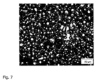
図7は、焼結層セクション58の表面の顕微鏡撮影を示し、図8は第2のワークピース層セクション56の表面の顕微鏡撮影を示している。図7の焼結層セクション58の撮影は、焼結が始まった粉末粒子を示しており、その粉末粒子はその表面の領域内では互いに結合されているが、その形状と大きさは、まだ実質的に、第2の原材料粉末54の粉末粒子の形状と大きさに相当する。それとは異なり、図8の第2のワークピース層セクション56の表面の顕微鏡撮影は、完全に溶融された表面構造を示しており、その中で個々の粉末粒子はもはや認識できない。
FIG. 7 shows a micrograph of the surface of
望まれる場合には、支持体18上に第2の原材料粉末54を塗布することによって第2のワークピース層セクション56を形成し、次に第2の原材料粉末54を電磁放射又は粒子放射によって選択的に照射する、上述したステップを、硬化されていない第2の原材料粉末54を加熱する前に、繰り返し実施することができる。その場合につながり合った多孔の焼結層セクション58は、複数の重なりあって配置された原材料粉末層セクションからなる「ブロック」として形成することができる。
If desired, a second
さらに、硬化されていない第2の原材料粉末54の一部のみを加熱し、それによって多孔の焼結層セクション58にさらに加工することができる。たとえば、硬化されていない第2の原材料粉末54の、構成部品の完成後にそれを包囲する構造内に収容される領域を加熱し、したがって焼結することを、省略することができる。
Additionally, only a portion of the second
図3から明らかなように、硬化されていない第2の原材料粉末54を加熱して焼結層セクション58を形成した後に、硬化された第1のワークピース層セクション52と、硬化された第2のワークピース層セクション56及び、第1と第2のワークピース層セクションを包囲する焼結層セクション58が、支持体18上に存在する。この堅固な「土台」上に、第1の原材料粉末50からなる他の原材料粉末層が塗布され(図4を参照)、かつ、三次元のマルチマテリアルワークピース12が層から層へ構築形成されて、所望の形状を有するまで、上記ステップが繰り返される。
3, after heating the uncured second
マルチマテリアルワークピース12の完成後に、ワークピース12は、ワークピース12を包囲する、重なり合って配置された焼結層セクション58と共に形成チャンバ20から取り出される;図5を参照。その後、分離装置48を用いてワークピース12が焼結層セクション58から分離される。特に、焼結層セクション58は、送風装置として形成された分離装置48によって処理されるので、一方でワークピース12が露出され(図6を参照)、他方では焼結層セクション58を形成する粉末粒が再び分離される。この粉末粒は、その後、たとえばふるいに掛けて処理し、最終的に他の三次元のワークピース12を製造するために再使用することができる。
なお、本発明の実施態様として、以下に示すものがある。
[態様1]
三次元のワークピース(12)を製造する方法であって:
(i)第1の原材料粉末(50)からなる原材料粉末層を形成するために、支持体(18)上に第1の原材料粉末(50)を塗布するステップと、
(ii)第1の原材料粉末(50)からなる硬化された第1のワークピース層セクション(52)を形成するために、第1の原材料粉末(50)からなる原材料粉末層を電磁放射又は粒子放射によって選択的に照射するステップと、
(iii)硬化されていない第1の原材料粉末(50)を支持体(18)から除去するステップと、
(iv)第1のワークピース層セクション(52)に隣接して、第2の原材料粉末(54)からなる原材料粉末層セクションを形成するために、支持体(18)上に第2の原材料粉末(54)を塗布するステップと、
(v)第1のワークピース層セクション(52)に隣接して、第2の原材料粉末(54)からなる硬化された第2のワークピース層セクション(56)を形成するために、原材料粉末層セクションを電磁放射又は粒子放射によって選択的に照射するステップと、
(vi)第1のワークピース層セクション(52)と第2のワークピース層セクション(56)に隣接して、第2の原材料粉末(54)からなるつながり合った多孔の焼結層セクション(58)を形成するために、硬化されていない第2の原材料粉末(54)を加熱するステップと、
を有する、三次元のワークピースを製造する方法。
[態様2]
ステップ(i)から(iii)が、ステップ(iv)の実施の前に複数回実施され、ステップ(i)から(iii)の各繰り返しにおいて、特に異なる第1の原材料粉末(50)が使用され、及び/又は
前記ステップ(iv)から(v)が、前記ステップ(vi)の実施の前に複数回実施されて、ステップ(vi)において、複数の重なりあって配置された原材料粉末層セクションからなるつながり合った多孔の焼結層セクション(58)が形成され、及び/又は
前記ステップ(iv)において、第1のワークピース層セクション(52)と第2のワークピース層セクション(56)に隣接して、第2の原材料粉末(54)からなるつながりあった多孔の焼結層セクション(58)を形成するために、硬化されていない第2の原材料粉末(54)の一部のみが加熱される、
態様1に記載の方法。
[態様3]
第2の原材料粉末(54)の材料が、第1の原材料粉末(50)の材料よりも、低い溶融温度及び/又は高い熱伝導率を有しており、及び/又は
第2の原材料粉末(54)の材料が、第1の原材料粉末(50)の材料よりも、安価である、
態様1又は2に記載の方法。
[態様4]
硬化されていない第2の原材料粉末(54)が、焼結層セクション(58)を形成するために、第2の原材料粉末(54)の溶融温度を下回る温度に加熱され、及び/又は
硬化されていない第2の原材料粉末(54)が、焼結層セクション(58)を形成するための、所望の期間の間加熱され、及び/又は
硬化されていない第2の原材料粉末(54)が、焼結層セクション(58)を形成するために、第2の原材料粉末(54)の材料の、その溶融温度への加熱をもたらす溶融エネルギ投入よりも小さい、エネルギ投入によって加熱される、
態様1から3のいずれか一態様に記載の方法。
[態様5]
-焼結層セクション(58)が、10から20%、の多孔率、特に10から15%の多孔率を有し、及び/又は
-第2のワークピース層セクション(56)が、0から5%の多孔率、特に0から2%の多孔率を有し、及び/又は
-焼結層セクション(58)が、その表面の領域内に互いに結合された粉末粒を含み、前記粉末粒の形状と大きさが、第2の原材料粉末(54)の粉末粒の形状と大きさに、実質的に相当する、
態様1から4のいずれか一態様に記載の方法。
[態様6]
硬化されていない第2の原材料粉末(54)が加熱装置(40)によって加熱され、前記加熱装置が硬化されていない第2の原材料粉末(54)に、硬化されていない第2の原材料粉末(54)の支持体(18)とは逆の表面を介し、及び/又は硬化されていない第2の原材料粉末(54)の支持体(18)側の表面を介して、熱エネルギを供給する、態様1から5のいずれか一態様に記載の方法。
[態様7]
加熱装置(40)が第1の加熱部材(42)を有し、前記第1の加熱部材が支持体(18)を収容するプロセスチャンバ(14)内で支持体(18)の上方に配置されており、及び/又はその場合に加熱装置(40)が第2の加熱部材(44)を有し、前記第2の加熱部材が、支持体(18)内に統合されており、あるいは支持体(18)を収容するプロセスチャンバ(14)の外部で支持体(18)の下方に配置されている、態様6に記載の方法。
[態様8]
ステップ(iii)内で支持体(18)から除去された、硬化されていない第1の原材料粉末(50)が、三次元のワークピース(12)を製造するために再使用される、態様1から7のいずれか一態様に記載の方法。
[態様9]
焼結層セクション(58)が、三次元のワークピース(12)を製造する形成プロセスの終了後に、分離プロセスによって、完成した三次元のワークピース(12)から分離され、その場合に分離プロセスが、好ましくは、個別化プロセス、特に焼結層セクション(58)を個々の粉末粒に個別化するための送風プロセスを有している、態様1から8のいずれか一態様に記載の方法。
[態様10]
個別化プロセス内で発生した、焼結層セクション(58)の個々の粉末粒が、三次元のワークピース(12)を製造するために再使用される、態様9に記載の方法。
[態様11]
三次元のワークピース(12)を製造する装置であって、前記装置が:
-粉末塗布装置(22)を有し、前記粉末塗布装置が、第1と第2の原材料粉末(50、54)を支持体(18)上に塗布するように、構成されており、
-照射装置(16)を有し、前記照射装置が、支持体(18)上に塗布された原材料粉末層を、電磁放射又は粒子砲者によって選択的に照射するように、構成されており、
-除去装置(24)を有し、前記除去装置が、硬化されていない第1の原材料粉末(50)を支持体(18)から除去するように、構成されており、
-加熱装置(40)を有し、前記加熱装置が、支持体(18)上に塗布された原材料粉末層を加熱するように、構成されており、かつ
-制御装置(46)を有し、前記制御装置が、前記装置(10)の駆動を次のように制御するように構成されている:
(i)第1の原材料粉末(50)からなる原材料粉末層を形成するために、粉末塗布装置(22)を用いて第1の原材料粉末(50)が支持体(18)上に塗布され、
(ii)第1の原材料粉末(50)からなる硬化された第1のワークピース層セクション(52)を形成するために、照射装置(16)を用いて第1の原材料粉末(50)からなる原材料粉末層が選択的に電磁放射又は粒子放射によって照射され、
(iii)除去装置(24)を用いて、硬化されていない第1の原材料粉末(50)が支持体(18)から除去され、
(iv)第1のワークピース層セクション(52)に隣接して、第2の原材料粉末(54)からなる原材料粉末層セクションを形成するために、粉末塗布装置(22)を用いて第2の原材料粉末(54)が支持体(18)上に塗布され、
(v)第1のワークピース層セクション(52)に隣接して、第2の原材料粉末(54)からなる硬化された第2のワークピース層セクション(56)を形成するために、照射装置(16)を用いて原材料粉末層セクションが電磁放射又は粒子放射によって照射され、かつ
(vi)第1のワークピース層セクション(52)と第2のワークピース層セクション(56)に隣接して、第2の原材料粉末(54)からなるつながりあった多孔の焼結層セクション(58)を形成するために、加熱装置(40)を用いて硬化されていない第2の原材料粉末(54)が加熱される、
三次元のワークピースを製造する装置。
[態様12]
制御装置(46)が、さらに、装置(10)の駆動を制御して、ステップ(iv)の実施前にステップ(i)から(iii)が多数回実施され、前記ステップ(i)から(iii)の各繰り返しにおいて、特に異なる第1の原材料粉末(50)が使用されるように、構成されており、及び/又は
制御装置(46)が、さらに、前記装置(10)の駆動を制御して、前記ステップ(vi)の実施前に、前記ステップ(iv)から(v)が複数回実施されるように、構成されており、前記ステップ(vi)において複数の互いに重なり合って配置された原材料粉末層セクションからなるつながりあった多孔の焼結層セクション(58)が形成され、及び/又は
制御装置(46)が、さらに、前記装置(10)を制御して、第1のワークピース層セクション(52)及び第2のワークピース層セクション(56)に隣接して、第2の原材料粉末(54)からなるつながりあった多孔の焼結層セクション(58)を形成するために、ステップ(iv)において硬化されていない第2の原材料粉末(54)の一部のみが加熱されるように、構成されている、
態様11に記載の装置。
[態様13]
制御装置(46)が、さらに、加熱装置(40)を制御して、
硬化されていない第2の原材料粉末(54)が、焼結層セクション(58)を形成するために、第2の原材料粉末(54)の材料の溶融温度を下回る温度に加熱され、及び/又は
硬化されていない第2の原材料粉末(54)が、焼結層セクション(58)を形成するために、所望の期間加熱され、及び/又は
硬化されていない第2の原材料粉末(54)が、焼結層セクション(58)を形成するために、第2の原材料粉末(54)の材料の溶融温度への加熱をもたらす溶融エネルギ投入よりも小さいエネルギ投入によって加熱される、
ように、整えられている、態様11又は12に記載の装置。
[態様14]
加熱装置(40)が、硬化されていない第2の原材料粉末(54)に、前記硬化されていない第2の原材料粉末(54)の表面であって支持体(18)とは逆の表面及び/又は前記硬化されていない第2の原材料粉末(54)の表面であって前記支持体(18)側の表面を介して熱エネルギを供給するように、整えられている、態様11から13のいずれか一態様に記載の装置。
[態様15]
加熱装置(40)が第1の加熱部材(42)を有し、前記第1の加熱部材が、支持体(18)を収容するプロセスチャンバ(14)内で支持体(18)の上方に配置されており、及び/又は、加熱装置(40)が第2の加熱部材(44)を有し、前記第2の加熱部材が支持体(18)内に統合されており、あるいは前記支持体(18)を収容する前記プロセスチャンバ(14)の外部で前記支持体(18)の下方に配置されている、態様14に記載の装置。
[態様16]
さらに分離装置(48)を有し、三次元のワークピース(12)を製造するための製造プロセスの終了後に、前記分離装置が、焼結層セクション(58)を完成した三次元のワークピース(12)から分離するように構成されており、前記分離装置(48)は、特に、焼結層セクション(58)を個々の粉末粒に分離するように、構成されている、態様11から15のいずれか一態様に記載の装置。
After completion of the
In addition, there exist some which are shown below as an embodiment of this invention.
[Aspect 1]
A method of manufacturing a three-dimensional workpiece (12), comprising:
(i) applying a first raw material powder (50) onto a support (18) to form a raw material powder layer of the first raw material powder (50);
(ii) subjecting the raw material powder layer of the first raw material powder (50) to electromagnetic radiation or particles to form a hardened first workpiece layer section (52) of the first raw material powder (50); selectively irradiating with radiation;
(iii) removing the uncured first raw material powder (50) from the support (18);
(iv) a second raw material powder on the support (18) to form a raw material powder layer section of the second raw material powder (54) adjacent to the first workpiece layer section (52); applying (54);
(v) a raw material powder layer to form a hardened second workpiece layer section (56) of a second raw material powder (54) adjacent the first workpiece layer section (52); selectively irradiating the section with electromagnetic radiation or particle radiation;
(vi) adjacent the first workpiece layer section (52) and the second workpiece layer section (56), an interconnected porous sintered layer section (58) of the second raw material powder (54); ) heating the uncured second raw material powder (54) to form
A method of manufacturing a three-dimensional workpiece, comprising:
[Aspect 2]
Steps (i) to (iii) are performed multiple times before step (iv) is performed, and in each iteration of steps (i) to (iii), in particular a different first raw material powder (50) is used , and/or
Said steps (iv) to (v) are performed a plurality of times prior to performing said step (vi) such that in step (vi) a plurality of interconnected raw material powder layer sections comprising a plurality of overlappingly arranged raw material powder layer sections a porous sintered layer section (58) is formed and/or
in step (iv), adjacent to the first workpiece layer section (52) and the second workpiece layer section (56), sintering connected porosity of the second raw material powder (54); only a portion of the uncured second raw material powder (54) is heated to form the layer section (58);
A method according to aspect 1.
[Aspect 3]
the material of the second raw material powder (54) has a lower melting temperature and/or a higher thermal conductivity than the material of the first raw material powder (50); and/or
the material of the second raw material powder (54) is cheaper than the material of the first raw material powder (50);
A method according to aspect 1 or 2.
[Aspect 4]
The uncured second raw material powder (54) is heated to a temperature below the melting temperature of the second raw material powder (54) to form the sintered layer section (58); and/or
The uncured second raw material powder (54) is heated for a desired period of time to form the sintered layer section (58), and/or
Melting energy input resulting in heating of the material of the second raw material powder (54) to its melting temperature so that the uncured second raw material powder (54) forms the sintered layer section (58). heated by the energy input, less than
A method according to any one of aspects 1-3.
[Aspect 5]
- the sintered layer section (58) has a porosity of 10 to 20%, in particular a porosity of 10 to 15%, and/or
- the second workpiece layer section (56) has a porosity of 0 to 5%, in particular a porosity of 0 to 2%, and/or
- the sintered layer section (58) comprises powder grains bonded together in a region of its surface, the shape and size of said powder grains being similar to the shape and size of the powder grains of the second raw material powder (54); substantially equivalent to
A method according to any one of aspects 1-4.
[Aspect 6]
The uncured second raw material powder (54) is heated by a heating device (40), said heating device heating the uncured second raw material powder (54) to the uncured second raw material powder ( 54) through the surface opposite the support (18) and/or through the surface of the uncured second raw material powder (54) facing the support (18); 6. The method of any one of aspects 1-5.
[Aspect 7]
A heating device (40) has a first heating member (42), said first heating member being disposed above the support (18) in a process chamber (14) containing the support (18). and/or in which case the heating device (40) comprises a second heating element (44), said second heating element being integrated in the support (18) or 7. A method according to aspect 6, located below the support (18) outside the process chamber (14) containing (18).
[Aspect 8]
Embodiment 1, wherein the uncured first raw material powder (50) removed from the support (18) in step (iii) is reused to manufacture the three-dimensional workpiece (12) 8. The method of any one of aspects 1 to 7.
[Aspect 9]
The sintered layer section (58) is separated from the finished three-dimensional workpiece (12) by a separation process after completion of the forming process that produces the three-dimensional workpiece (12), where the separation process 9. A method according to any one of aspects 1 to 8, preferably comprising a singulation process, in particular a blowing process for singulating the sintered layer section (58) into individual powder grains.
[Aspect 10]
10. The method of aspect 9, wherein the individual powder grains of the sintered layer section (58) generated within the singulation process are reused to manufacture the three-dimensional workpiece (12).
[Aspect 11]
An apparatus for manufacturing a three-dimensional workpiece (12), said apparatus comprising:
- comprising a powder applicator (22), said powder applicator being adapted to apply first and second raw material powders (50, 54) onto a support (18),
- comprising an irradiation device (16), said irradiation device being adapted to selectively irradiate a raw material powder layer applied on a support (18) by means of electromagnetic radiation or a particle gunner,
- having a removal device (24), said removal device being adapted to remove the uncured first raw material powder (50) from the support (18);
- a heating device (40), said heating device being adapted to heat the raw material powder layer applied on the support (18), and
- having a control device (46), said control device being arranged to control the actuation of said device (10) as follows:
(i) applying a first raw material powder (50) onto a support (18) using a powder applicator (22) to form a raw material powder layer of the first raw material powder (50);
(ii) the first raw material powder (50) using the irradiation device (16) to form a cured first workpiece layer section (52) of the first raw material powder (50); the raw material powder layer is selectively irradiated with electromagnetic radiation or particle radiation;
(iii) removing the uncured first raw material powder (50) from the support (18) using a removal device (24);
(iv) using the powder applicator (22) to form a raw material powder layer section of a second raw material powder (54) adjacent to the first workpiece layer section (52); a raw material powder (54) is applied onto the support (18);
(v) an irradiation device ( 16) is used to irradiate the raw material powder layer section with electromagnetic radiation or particle radiation, and
(vi) adjacent the first workpiece layer section (52) and the second workpiece layer section (56), a continuous porous sintered layer section (58) of the second raw material powder (54); ) is heated with the heating device (40) to form the uncured second raw material powder (54),
Equipment for manufacturing three-dimensional workpieces.
[Aspect 12]
A control device (46) further controls the driving of the device (10) such that steps (i) to (iii) are performed a number of times before step (iv) is performed, and steps (i) to (iii) are performed a number of times. ), in particular a different first raw material powder (50) is used in each iteration;
The controller (46) is further configured to control the driving of the device (10) such that steps (iv) to (v) are performed multiple times before step (vi) is performed. wherein in step (vi) a contiguous porous sintered layer section (58) consisting of a plurality of raw material powder layer sections arranged on top of each other is formed; and/or
A controller (46) further controls the apparatus (10) to deposit a second raw material powder adjacent to the first workpiece layer section (52) and the second workpiece layer section (56). so that only a portion of the second raw material powder (54) that is not hardened in step (iv) is heated to form a contiguous porous sintered layer section (58) consisting of (54) ,It is configured,
12. Apparatus according to aspect 11.
[Aspect 13]
The controller (46) further controls the heating device (40) to
The uncured second raw material powder (54) is heated to a temperature below the melting temperature of the material of the second raw material powder (54) to form the sintered layer section (58), and/or
The uncured second raw material powder (54) is heated for a desired period of time to form the sintered layer section (58) and/or
The uncured second raw material powder (54) rather than melting energy input resulting in heating of the material of the second raw material powder (54) to a melting temperature to form the sintered layer section (58). heated by a small energy input,
13. Apparatus according to
[Aspect 14]
A heating device (40) heats the uncured second raw material powder (54) to a surface of said uncured second raw material powder (54) opposite the support (18) and /or according to aspects 11 to 13, wherein the surface of the uncured second raw material powder (54) is arranged to supply thermal energy through the surface facing the support (18). A device according to any one of the aspects.
[Aspect 15]
A heating device (40) has a first heating member (42), said first heating member being positioned above a support (18) within a process chamber (14) containing the support (18). and/or the heating device (40) comprises a second heating element (44), said second heating element being integrated within the support (18) or said support ( 15. Apparatus according to
[Aspect 16]
It further comprises a separating device (48), said separating device separating the sintered layer section (58) from the finished three-dimensional workpiece ( 12), wherein said separating device (48) is in particular configured to separate the sintered layer section (58) into individual powder grains. A device according to any one of the aspects.
Claims (16)
(i)第1の原材料粉末(50)からなる原材料粉末層を形成するために、支持体(18)上に第1の原材料粉末(50)を塗布するステップと、
(ii)第1の原材料粉末(50)からなる硬化された第1のワークピース層セクション(52)を形成するために、第1の原材料粉末(50)からなる原材料粉末層を電磁放射又は粒子放射によって選択的に照射するステップと、
(iii)硬化されていない第1の原材料粉末(50)を支持体(18)から除去するステップと、
(iv)第1のワークピース層セクション(52)に隣接して、第2の原材料粉末(54)からなる原材料粉末層セクションを形成するために、支持体(18)上に第2の原材料粉末(54)を塗布するステップと、
(v)第1のワークピース層セクション(52)に隣接して、第2の原材料粉末(54)からなる硬化された第2のワークピース層セクション(56)を形成するために、原材料粉末層セクションを電磁放射又は粒子放射によって選択的に照射するステップと、
(vi)第1のワークピース層セクション(52)と第2のワークピース層セクション(56)に隣接して、第2の原材料粉末(54)からなるつながり合った多孔の焼結層セクション(58)を形成するために、第2の原材料粉末(54)からなる前記原材料粉末層セクションの部位選択的な照射の後に残る硬化されていない第2の原材料粉末(54)を加熱するステップと、
を有する、三次元のワークピースを製造する方法。 A method of manufacturing a three-dimensional workpiece (12), comprising:
(i) applying a first raw material powder (50) onto a support (18) to form a raw material powder layer of the first raw material powder (50);
(ii) subjecting the raw material powder layer of the first raw material powder (50) to electromagnetic radiation or particles to form a hardened first workpiece layer section (52) of the first raw material powder (50); selectively irradiating with radiation;
(iii) removing the uncured first raw material powder (50) from the support (18);
(iv) a second raw material powder on the support (18) to form a raw material powder layer section of the second raw material powder (54) adjacent to the first workpiece layer section (52); applying (54);
(v) a raw material powder layer to form a hardened second workpiece layer section (56) of a second raw material powder (54) adjacent the first workpiece layer section (52); selectively irradiating the section with electromagnetic radiation or particle radiation;
(vi) adjacent the first workpiece layer section (52) and the second workpiece layer section (56), an interconnected porous sintered layer section (58) of the second raw material powder (54); heating the uncured second raw material powder (54) remaining after site-selective irradiation of said raw material powder layer section of the second raw material powder (54) to form a );
A method of manufacturing a three-dimensional workpiece, comprising:
前記ステップ(iv)から(v)が、前記ステップ(vi)の実施の前に複数回実施されて、ステップ(vi)において、複数の重なりあって配置された原材料粉末層セクションからなるつながり合った多孔の焼結層セクション(58)が形成され、及び/又は
前記ステップ(iv)において、第1のワークピース層セクション(52)と第2のワークピース層セクション(56)に隣接して、第2の原材料粉末(54)からなるつながりあった多孔の焼結層セクション(58)を形成するために、硬化されていない第2の原材料粉末(54)の一部のみが加熱される、
請求項1に記載の方法。 Steps (i) to (iii) are performed multiple times before step (iv) is performed, and in each iteration of steps (i) to (iii), in particular a different first raw material powder (50) is used and/or wherein steps (iv) through (v) are performed a plurality of times prior to performing step (vi) such that in step (vi), from a plurality of overlappingly arranged raw material powder layer sections an interconnected porous sintered layer section (58) is formed and/or adjoins the first workpiece layer section (52) and the second workpiece layer section (56) in step (iv); Thus, only a portion of the uncured second raw material powder (54) is heated to form a connected porous sintered layer section (58) of the second raw material powder (54). Ru
The method of claim 1.
第2の原材料粉末(54)の材料が、第1の原材料粉末(50)の材料よりも、安価である、
請求項1又は2に記載の方法。 The material of the second raw material powder (54) has a lower melting temperature and/or a higher thermal conductivity than the material of the first raw material powder (50), and/or The material of 54) is cheaper than the material of the first raw material powder (50),
3. A method according to claim 1 or 2.
硬化されていない第2の原材料粉末(54)が、焼結層セクション(58)を形成するための、所望の期間の間加熱され、及び/又は
硬化されていない第2の原材料粉末(54)が、焼結層セクション(58)を形成するために、第2の原材料粉末(54)の材料の、その溶融温度への加熱をもたらす溶融エネルギ投入よりも小さい、エネルギ投入によって加熱される、
請求項1から3のいずれか1項に記載の方法。 The uncured second raw material powder (54) is heated to a temperature below the melting temperature of the second raw material powder (54) and/or cured to form the sintered layer section (58). the uncured second raw material powder (54) is heated for a desired period of time to form the sintered layer section (58); and/or the uncured second raw material powder (54) is heating the material of the second raw material powder (54) to form the sintered layer section (58) by an energy input less than the melting energy input that results in heating to its melting temperature;
4. A method according to any one of claims 1-3.
-第2のワークピース層セクション(56)が、0から5%の多孔率、特に0から2%の多孔率を有し、及び/又は
-焼結層セクション(58)が、その表面の領域内に互いに結合された粉末粒を含み、前記粉末粒の形状と大きさが、第2の原材料粉末(54)の粉末粒の形状と大きさに、実質的に相当する、
請求項1から4のいずれか1項に記載の方法。 - the sintered layer section (58) has a porosity of 10 to 20%, in particular a porosity of 10 to 15%; and/or - the second workpiece layer section (56) has a porosity of 0 to 5. % porosity, in particular 0 to 2% porosity, and/or - the sintered layer section (58) comprises powder grains bonded together in the region of its surface, the shape of said powder grains and sizes correspond substantially to the shape and size of the powder grains of the second raw material powder (54),
5. A method according to any one of claims 1-4.
-粉末塗布装置(22)を有し、前記粉末塗布装置が、第1と第2の原材料粉末(50、54)を支持体(18)上に塗布するように、構成されており、
-照射装置(16)を有し、前記照射装置が、支持体(18)上に塗布された原材料粉末層を、電磁放射又は粒子砲者によって選択的に照射するように、構成されており、
-除去装置(24)を有し、前記除去装置が、硬化されていない第1の原材料粉末(50)を支持体(18)から除去するように、構成されており、
-加熱装置(40)を有し、前記加熱装置が、支持体(18)上に塗布された原材料粉末層を加熱するように、構成されており、かつ
-制御装置(46)を有し、前記制御装置が、前記装置(10)の駆動を次のように制御するように構成されている:
(i)第1の原材料粉末(50)からなる原材料粉末層を形成するために、粉末塗布装置(22)を用いて第1の原材料粉末(50)が支持体(18)上に塗布され、
(ii)第1の原材料粉末(50)からなる硬化された第1のワークピース層セクション(52)を形成するために、前記照射装置(16)を用いて第1の原材料粉末(50)からなる原材料粉末層が選択的に電磁放射又は粒子放射によって照射され、
(iii)前記除去装置(24)を用いて、硬化されていない第1の原材料粉末(50)が支持体(18)から除去され、
(iv)第1のワークピース層セクション(52)に隣接して、第2の原材料粉末(54)からなる原材料粉末層セクションを形成するために、粉末塗布装置(22)を用いて第2の原材料粉末(54)が支持体(18)上に塗布され、
(v)第1のワークピース層セクション(52)に隣接して、第2の原材料粉末(54)からなる硬化された第2のワークピース層セクション(56)を形成するために、照射装置(16)を用いて原材料粉末層セクションが電磁放射又は粒子放射によって選択的に照射され、かつ
(vi)第1のワークピース層セクション(52)と第2のワークピース層セクション(56)に隣接して、第2の原材料粉末(54)からなるつながりあった多孔の焼結層セクション(58)を形成するために、前記加熱装置(40)を用いて、第2の原材料粉末(54)からなる前記原材料粉末層セクションの部位選択的な照射の後に残る硬化されていない第2の原材料粉末(54)が加熱される、
三次元のワークピースを製造する装置。 An apparatus (10) for manufacturing a three-dimensional workpiece (12), said apparatus comprising:
- comprising a powder applicator (22), said powder applicator being adapted to apply first and second raw material powders (50, 54) onto a support (18),
- comprising an irradiation device (16), said irradiation device being adapted to selectively irradiate a raw material powder layer applied on a support (18) by means of electromagnetic radiation or a particle gunner,
- having a removal device (24), said removal device being adapted to remove the uncured first raw material powder (50) from the support (18);
- a heating device (40), said heating device being adapted to heat the raw material powder layer applied on the support (18), and - having a control device (46), The control device is arranged to control the driving of the device (10) as follows:
(i) applying a first raw material powder (50) onto a support (18) using a powder applicator (22) to form a raw material powder layer of the first raw material powder (50);
(ii) from the first raw material powder (50) using said irradiation device (16) to form a cured first workpiece layer section (52) of the first raw material powder (50); a raw material powder layer is selectively irradiated with electromagnetic radiation or particle radiation;
(iii) removing the uncured first raw material powder (50) from the support (18) using said removal device (24);
(iv) using the powder applicator (22) to form a raw material powder layer section of a second raw material powder (54) adjacent to the first workpiece layer section (52); a raw material powder (54) is applied onto the support (18);
(v) an irradiation device ( 16) selectively irradiating the raw material powder layer section with electromagnetic radiation or particle radiation, and (vi) adjacent to the first workpiece layer section (52) and the second workpiece layer section (56); of the second raw material powder (54) using the heating device (40) to form a continuous porous sintered layer section (58) of the second raw material powder (54). the uncured second raw material powder (54) remaining after site-selective irradiation of said raw material powder layer section is heated;
Equipment for manufacturing three-dimensional workpieces.
制御装置(46)が、さらに、前記装置(10)の駆動を制御して、前記ステップ(vi)の実施前に、前記ステップ(iv)から(v)が複数回実施されるように、構成されており、前記ステップ(vi)において複数の互いに重なり合って配置された原材料粉末層セクションからなるつながりあった多孔の焼結層セクション(58)が形成され、及び/又は
制御装置(46)が、さらに、前記装置(10)を制御して、第1のワークピース層セクション(52)及び第2のワークピース層セクション(56)に隣接して、第2の原材料粉末(54)からなるつながりあった多孔の焼結層セクション(58)を形成するために、ステップ(iv)において硬化されていない第2の原材料粉末(54)の一部のみが加熱されるように、構成されている、
請求項11に記載の装置。 A control device (46) further controls the driving of the device (10) such that steps (i) to (iii) are performed a number of times before step (iv) is performed, and steps (i) to (iii) are performed a number of times. ), in particular a different first raw material powder (50) is used, and/or the control device (46) further controls the driving of said device (10) and the step (iv) to (v) are performed a plurality of times before the step (vi) is performed, and the plurality of raw materials placed on top of each other in the step (vi) a contiguous porous sintered layer section (58) consisting of a powder layer section is formed; and/or the controller (46) further controls the apparatus (10) to form a first workpiece layer section (52) and adjacent to the second workpiece layer section (56) to form an interconnected porous sintered layer section (58) of the second raw material powder (54), step (iv) ) is configured such that only a portion of the second raw material powder (54) that is not cured in the
12. Apparatus according to claim 11.
硬化されていない第2の原材料粉末(54)が、焼結層セクション(58)を形成するために、第2の原材料粉末(54)の材料の溶融温度を下回る温度に加熱され、及び/又は
硬化されていない第2の原材料粉末(54)が、焼結層セクション(58)を形成するために、所望の期間加熱され、及び/又は
硬化されていない第2の原材料粉末(54)が、焼結層セクション(58)を形成するために、第2の原材料粉末(54)の材料の溶融温度への加熱をもたらす溶融エネルギ投入よりも小さいエネルギ投入によって加熱される、
ように、整えられている、請求項11又は12に記載の装置。 The controller (46) further controls the heating device (40) to
The uncured second raw material powder (54) is heated to a temperature below the melting temperature of the material of the second raw material powder (54) to form the sintered layer section (58), and/or the uncured second raw material powder (54) is heated for a desired period of time to form the sintered layer section (58); and/or the uncured second raw material powder (54) is heated to form the sintered layer section (58) with an energy input that is less than the melting energy input that results in heating the material of the second raw material powder (54) to a melting temperature;
13. Apparatus according to claim 11 or 12, arranged to.
Applications Claiming Priority (3)
| Application Number | Priority Date | Filing Date | Title |
|---|---|---|---|
| DE102019116503.2A DE102019116503A1 (en) | 2019-06-18 | 2019-06-18 | Method and device for manufacturing a multi-material workpiece |
| DE102019116503.2 | 2019-06-18 | ||
| PCT/EP2020/066553 WO2020254284A1 (en) | 2019-06-18 | 2020-06-16 | Method and device for producing a multi-material workpiece |
Publications (2)
| Publication Number | Publication Date |
|---|---|
| JP2022537561A JP2022537561A (en) | 2022-08-26 |
| JP7320084B2 true JP7320084B2 (en) | 2023-08-02 |
Family
ID=71103382
Family Applications (1)
| Application Number | Title | Priority Date | Filing Date |
|---|---|---|---|
| JP2021575432A Active JP7320084B2 (en) | 2019-06-18 | 2020-06-16 | Manufacturing method and manufacturing equipment for multi-material workpiece |
Country Status (6)
| Country | Link |
|---|---|
| US (1) | US20220193771A1 (en) |
| EP (1) | EP3986645B8 (en) |
| JP (1) | JP7320084B2 (en) |
| CN (1) | CN114126787A (en) |
| DE (1) | DE102019116503A1 (en) |
| WO (1) | WO2020254284A1 (en) |
Families Citing this family (1)
| Publication number | Priority date | Publication date | Assignee | Title |
|---|---|---|---|---|
| FR3130660A1 (en) * | 2021-12-16 | 2023-06-23 | Safran Additive Manufacturing Campus | Powder bed additive manufacturing process |
Citations (5)
| Publication number | Priority date | Publication date | Assignee | Title |
|---|---|---|---|---|
| JP2007070655A (en) | 2005-09-05 | 2007-03-22 | Matsushita Electric Ind Co Ltd | Three-dimensional structure and production method therefor |
| JP2009001900A (en) | 2007-05-23 | 2009-01-08 | Panasonic Electric Works Co Ltd | Process for three-dimensional configuration modeling |
| JP2014516387A (en) | 2011-04-19 | 2014-07-10 | フェニックス システム | Method for producing an object by solidifying powder using a laser |
| JP2018020441A (en) | 2016-08-01 | 2018-02-08 | 株式会社オメガ | Production method of three-dimensionally shaped molded article |
| JP2019081937A (en) | 2017-10-31 | 2019-05-30 | 株式会社Ihi | Powder saving device and powder saving method |
Family Cites Families (14)
| Publication number | Priority date | Publication date | Assignee | Title |
|---|---|---|---|---|
| JP3446733B2 (en) * | 2000-10-05 | 2003-09-16 | 松下電工株式会社 | Method and apparatus for manufacturing three-dimensional shaped object |
| US20020090410A1 (en) * | 2001-01-11 | 2002-07-11 | Shigeaki Tochimoto | Powder material removing apparatus and three dimensional modeling system |
| JP5588925B2 (en) * | 2011-05-23 | 2014-09-10 | パナソニック株式会社 | Manufacturing method of three-dimensional shaped object |
| CN105026076B (en) * | 2013-02-27 | 2017-06-09 | Slm方案集团股份公司 | Apparatus and method for producing the workpiece with customization microstructure |
| EP2878402A1 (en) * | 2013-12-02 | 2015-06-03 | SLM Solutions Group AG | Apparatus and method for producing three-dimensional work pieces with a radiation detection device |
| DE102015204630A1 (en) * | 2015-03-13 | 2016-09-15 | Eos Gmbh Electro Optical Systems | Method and device for producing a three-dimensional object with improved surface quality |
| EP3156153B1 (en) * | 2015-10-16 | 2019-05-22 | SLM Solutions Group AG | Apparatus for producing a three-dimensional work piece which includes a heating system |
| JP6687887B2 (en) * | 2016-02-18 | 2020-04-28 | セイコーエプソン株式会社 | Ceramic parts and three-dimensional manufacturing method of ceramic parts |
| DE102016208196B4 (en) * | 2016-05-12 | 2019-08-29 | Fraunhofer-Gesellschaft zur Förderung der angewandten Forschung e.V. | Method for the generative production of three-dimensional composite components |
| EP3278908B1 (en) * | 2016-08-02 | 2020-01-08 | Siemens Aktiengesellschaft | Support structure, method of providing the same and method of additively manufacturing |
| EP3281727B8 (en) * | 2016-08-10 | 2023-11-22 | Nikon SLM Solutions AG | Apparatus for producing three-dimensional workpiece comprising a plurality of powder application devices |
| DE102016124401A1 (en) * | 2016-12-14 | 2018-06-14 | Cl Schutzrechtsverwaltungs Gmbh | Method for the additive production of a three-dimensional object |
| JP6760860B2 (en) * | 2017-01-25 | 2020-09-23 | 三菱重工業株式会社 | Laminated molding equipment and laminated molding method |
| DE102017208862A1 (en) * | 2017-05-24 | 2018-11-29 | Siemens Aktiengesellschaft | Method and device for producing a workpiece by means of selective laser melting |
-
2019
- 2019-06-18 DE DE102019116503.2A patent/DE102019116503A1/en active Pending
-
2020
- 2020-06-16 JP JP2021575432A patent/JP7320084B2/en active Active
- 2020-06-16 CN CN202080052027.9A patent/CN114126787A/en active Pending
- 2020-06-16 US US17/619,320 patent/US20220193771A1/en active Pending
- 2020-06-16 EP EP20733405.3A patent/EP3986645B8/en active Active
- 2020-06-16 WO PCT/EP2020/066553 patent/WO2020254284A1/en unknown
Patent Citations (5)
| Publication number | Priority date | Publication date | Assignee | Title |
|---|---|---|---|---|
| JP2007070655A (en) | 2005-09-05 | 2007-03-22 | Matsushita Electric Ind Co Ltd | Three-dimensional structure and production method therefor |
| JP2009001900A (en) | 2007-05-23 | 2009-01-08 | Panasonic Electric Works Co Ltd | Process for three-dimensional configuration modeling |
| JP2014516387A (en) | 2011-04-19 | 2014-07-10 | フェニックス システム | Method for producing an object by solidifying powder using a laser |
| JP2018020441A (en) | 2016-08-01 | 2018-02-08 | 株式会社オメガ | Production method of three-dimensionally shaped molded article |
| JP2019081937A (en) | 2017-10-31 | 2019-05-30 | 株式会社Ihi | Powder saving device and powder saving method |
Also Published As
| Publication number | Publication date |
|---|---|
| US20220193771A1 (en) | 2022-06-23 |
| EP3986645B8 (en) | 2023-12-06 |
| EP3986645B1 (en) | 2023-10-04 |
| JP2022537561A (en) | 2022-08-26 |
| WO2020254284A1 (en) | 2020-12-24 |
| EP3986645A1 (en) | 2022-04-27 |
| EP3986645C0 (en) | 2023-10-04 |
| DE102019116503A1 (en) | 2020-12-24 |
| CN114126787A (en) | 2022-03-01 |
Similar Documents
| Publication | Publication Date | Title |
|---|---|---|
| TWI774785B (en) | Additive manufacturing with mulitple mirror scanners | |
| JP6053745B2 (en) | Method and control apparatus for controlling irradiation system | |
| US11801633B2 (en) | Apparatuses for continuously refreshing a recoater blade for additive manufacturing including a blade feed unit and arm portion | |
| US9901983B2 (en) | Method of applying multiple materials with selective laser melting on a 3D article | |
| US11117194B2 (en) | Additive manufacturing having energy beam and lamp array | |
| US20170189965A1 (en) | Materials and formulations for three-dimensional printing | |
| JP6186332B2 (en) | Powder processing apparatus and powder processing method for use in a three-dimensional workpiece manufacturing machine | |
| KR102495072B1 (en) | Additive manufacturing using multi-sided and galvo mirror scanners | |
| KR20180021916A (en) | Lamination Manufacturing Using Preheating | |
| US10967575B2 (en) | Method and device for the generative manufacturing of a three-dimensional object | |
| JP2019077935A (en) | Three-dimensional molding device and method for manufacturing three-dimensional molded object | |
| US11104068B2 (en) | Method for enhancing the finish of additively-manufactured components | |
| JP7320084B2 (en) | Manufacturing method and manufacturing equipment for multi-material workpiece | |
| US11123798B2 (en) | Method for manufacturing a semi-finished product and a workpiece | |
| WO2022248069A1 (en) | Heat transfer device for additive manufacturing |
Legal Events
| Date | Code | Title | Description |
|---|---|---|---|
| A521 | Request for written amendment filed |
Free format text: JAPANESE INTERMEDIATE CODE: A523 Effective date: 20220201 |
|
| A621 | Written request for application examination |
Free format text: JAPANESE INTERMEDIATE CODE: A621 Effective date: 20220201 |
|
| A977 | Report on retrieval |
Free format text: JAPANESE INTERMEDIATE CODE: A971007 Effective date: 20230111 |
|
| A131 | Notification of reasons for refusal |
Free format text: JAPANESE INTERMEDIATE CODE: A131 Effective date: 20230221 |
|
| A521 | Request for written amendment filed |
Free format text: JAPANESE INTERMEDIATE CODE: A523 Effective date: 20230519 |
|
| TRDD | Decision of grant or rejection written | ||
| A01 | Written decision to grant a patent or to grant a registration (utility model) |
Free format text: JAPANESE INTERMEDIATE CODE: A01 Effective date: 20230704 |
|
| A61 | First payment of annual fees (during grant procedure) |
Free format text: JAPANESE INTERMEDIATE CODE: A61 Effective date: 20230721 |
|
| R150 | Certificate of patent or registration of utility model |
Ref document number: 7320084 Country of ref document: JP Free format text: JAPANESE INTERMEDIATE CODE: R150 |