CN113787346A - Aluminum profile milling and sawing combined machining center - Google Patents
Aluminum profile milling and sawing combined machining center Download PDFInfo
- Publication number
- CN113787346A CN113787346A CN202111191051.3A CN202111191051A CN113787346A CN 113787346 A CN113787346 A CN 113787346A CN 202111191051 A CN202111191051 A CN 202111191051A CN 113787346 A CN113787346 A CN 113787346A
- Authority
- CN
- China
- Prior art keywords
- sawing
- unit
- milling
- workpiece
- clamping
- Prior art date
- Legal status (The legal status is an assumption and is not a legal conclusion. Google has not performed a legal analysis and makes no representation as to the accuracy of the status listed.)
- Pending
Links
Images


Classifications
-
- B—PERFORMING OPERATIONS; TRANSPORTING
- B23—MACHINE TOOLS; METAL-WORKING NOT OTHERWISE PROVIDED FOR
- B23P—METAL-WORKING NOT OTHERWISE PROVIDED FOR; COMBINED OPERATIONS; UNIVERSAL MACHINE TOOLS
- B23P23/00—Machines or arrangements of machines for performing specified combinations of different metal-working operations not covered by a single other subclass
- B23P23/02—Machine tools for performing different machining operations
-
- B—PERFORMING OPERATIONS; TRANSPORTING
- B23—MACHINE TOOLS; METAL-WORKING NOT OTHERWISE PROVIDED FOR
- B23Q—DETAILS, COMPONENTS, OR ACCESSORIES FOR MACHINE TOOLS, e.g. ARRANGEMENTS FOR COPYING OR CONTROLLING; MACHINE TOOLS IN GENERAL CHARACTERISED BY THE CONSTRUCTION OF PARTICULAR DETAILS OR COMPONENTS; COMBINATIONS OR ASSOCIATIONS OF METAL-WORKING MACHINES, NOT DIRECTED TO A PARTICULAR RESULT
- B23Q7/00—Arrangements for handling work specially combined with or arranged in, or specially adapted for use in connection with, machine tools, e.g. for conveying, loading, positioning, discharging, sorting
Abstract
The invention discloses an aluminum profile milling and sawing combined machining center which comprises a feeding unit, a milling and sawing host unit and an unloading unit, wherein the milling and sawing host unit comprises a front positioning and clamping device, a milling unit, a sawing unit and a clamping jaw discharging device, the front positioning and clamping device is used for clamping a workpiece, the milling unit, the sawing unit and the clamping jaw discharging device are sequentially arranged, the front positioning and clamping device is arranged behind the feeding unit and is matched with the feeding unit for use, and the clamping jaw discharging device is arranged in front of the unloading unit and is matched with the unloading unit for use. The device is special equipment for drilling, milling grooves and saw cutting of aluminum door and window profiles, and can complete drilling, milling grooves and saw cutting of 45 degrees/135 degrees and 90 degrees in a profile horizontal plane on the basis of one-time feeding. The device has the remarkable characteristics of automation, digitalization, intellectualization and the like, has the advantages of reliable performance, simple operation, convenient maintenance and the like, and is ideal equipment for processing aluminum door and window profiles.
Description
Technical Field
The invention particularly relates to an aluminum profile milling and sawing combined machining center.
Background
The prior art situation is as follows: at present, the processing procedures of a lock hole, a handle hole, a water leakage hole, an installation hole and the like of an aluminum door and window profile are processed by using equipment such as a single-sleeve processing center, a multi-station pneumatic punching machine, a multi-head drill and the like in a manner of manual feeding and discharging and tool positioning, and the defects of high labor intensity of workers, poor product quality consistency, low production efficiency and the like exist; or the material is processed by adopting a single-set processing center, a numerical control punch, a numerical control drilling machine and other equipment and adopting a logistics line sorting mode, a robot mode or a manual feeding and discharging mode, and a plurality of adverse factors such as large investment, large occupied area and the like exist. The former has low equipment numerical control rate and poor information intercommunication capability, and the latter has high investment, wide occupied area and high requirement capability on key post personnel, and the excessive equipment cost investment is an insurmountable gap for door and window production enterprises with small scale. In order to improve the situation, the invention provides an aluminum profile milling and sawing combined machining center.
Disclosure of Invention
In order to solve the technical problems, the invention aims to provide an aluminum profile milling and sawing combined machining center which comprises a feeding unit, a milling and sawing host unit and an unloading unit, wherein the milling and sawing host unit comprises a front positioning and clamping device, a milling unit, a sawing unit and a clamping jaw discharging device, the front positioning and clamping device is used for clamping a workpiece and is arranged in sequence, the front positioning and clamping device is arranged behind the feeding unit and is matched with the feeding unit, and the clamping jaw discharging device is arranged in front of the unloading unit and is matched with the unloading unit.
As preferred, mill the unit and saw cut one side of unit and still be provided with the chip cleaner, and preceding positioning and clamping device, mill the unit, saw cut unit, clamping jaw discharging device and all fix the top at the host computer base, just be provided with the opening that is used for the ejection of compact on the host computer base, the initiating terminal setting of chip cleaner is in host computer base open-ended below.
Preferably, the feeding unit comprises a feeding base, a feeding manipulator is arranged on the feeding base, the feeding manipulator is arranged on a movable base, the movable base is arranged on a guide rail and can move in the workpiece running direction, the feeding manipulator can move in the horizontal direction and the vertical direction which are perpendicular to the moving direction of the movable base, axial movement of the feeding manipulator on three-axis coordinate axes is realized, a synchronous belt mechanism which is perpendicular to the workpiece running direction is further arranged above the feeding base and is driven by a speed reduction motor in a connecting mode, the synchronous belt mechanisms are arranged side by side, an industrial camera detection device is further arranged on one side, close to the main unit of the milling and sawing machine, of the feeding unit, a lifting positioning roller device, a workpiece feeding device and a workpiece pre-positioning device are further arranged at the position of the synchronous belt mechanism, and the width, the width and the width of the workpiece are positioned and detected, Height and length.
Preferably, the front positioning and clamping device comprises a support arranged above the base of the main machine, a horizontal supporting roller, a rear vertical roller, an upper nip roller and a side nip roller are arranged on the support and used for clamping the upper surface, the lower surface, the front surface and the rear surface and ensuring continuous feeding, the upper nip roller is driven by an upper nip cylinder, and the side nip roller is driven by a side nip cylinder.
Preferably, the milling unit comprises milling columns, horizontal sliding plates and vertical sliding plates which are arranged in a layered mode, openings are formed in the center of the milling units and can be penetrated through by workpieces, the milling columns can move in the moving direction of the workpieces, the horizontal sliding plates are arranged on the milling columns and can move in the horizontal direction, the vertical sliding plates are arranged on the horizontal sliding plates and can move in the vertical direction and are driven by servo motors and ball screws, a plurality of small sliding plates are arranged at one ends, close to the front positioning and clamping devices, of the vertical sliding plates, and electric spindles are arranged on the small sliding plates and can move through cylinders.
Preferably, the number of the small sliding plates is 6, the number of the small sliding plates is 2, the number of the small sliding plates is 4, the small sliding plates are symmetrically arranged in the horizontal direction, each small sliding plate is provided with an electric spindle driven to move by a cylinder, and the direction of an output shaft of each electric spindle faces towards an opening in the center.
Preferably, the sawing unit comprises a 90 ° sawing electric spindle, a 45 ° sawing electric spindle and a 135 ° sawing electric spindle, and each is mounted with a saw blade for cutting.
As preferred, 90 saw cut the electricity main shaft setting on the motor slide of directly cutting, directly cut the motor slide setting on little slip table, can remove through the pneumatic drive device drive, 90 saw cut electricity main shaft below still is provided with little base, 90 saw cut one side of electricity main shaft sets up the saw stand, be provided with the slide that can reciprocate on the saw stand, be provided with the horizontal sliding plate that saw that can horizontal migration on the slide, saw cut both sides respectively about the horizontal sliding plate and be provided with 45 saw cut electricity main shaft and 135 saw cut electricity main shaft, saw cut the ascending moving range of horizontal sliding plate in the fore-and-aft direction of slide and be 5mm ~10mm, 45 saw cut electricity main shaft and 135 saw cut electricity main shaft department still set gradually saw preceding clamping device and saw cut clamping device from the moving direction of work piece for fixed work piece.
Preferably, the clamping jaw discharging device comprises a discharging rack and a small base, a movable discharging sliding plate is arranged on the discharging rack, a servo device used for driving the discharging sliding plate to move is arranged on the discharging sliding plate, and a saw cut rear clamping device used for clamping a workpiece is further arranged on the discharging sliding plate.
Preferably, the unit of unloading includes the base and sets up the multirow hold-in range mechanism of unloading on the base, hold-in range mechanism of unloading is driven by gear motor, hold-in range mechanism's initiating terminal of unloading is provided with lift support material roller device for receive the work piece that clamping jaw discharging device transported out, hold-in range mechanism middle part of unloading is provided with beats mark positioner, it is provided with the automatic mark device of beating that the cooperation was used to beat mark positioner one side.
Compared with the prior art, the invention has the following beneficial effects: the production line comprises a feeding unit, a milling and sawing host unit, a discharging unit and the like, is special equipment for drilling, milling grooves and sawing aluminum door and window profiles, and can complete the drilling, milling grooves and the sawing of 45 degrees/135 degrees and 90 degrees in the horizontal plane of the profiles on the basis of one-time feeding. The device has the remarkable characteristics of automation, digitalization, intellectualization and the like, has the advantages of reliable performance, simple operation, convenient maintenance and the like, and is ideal equipment for processing aluminum door and window profiles. Through servo control, each unit is in coordination, realized the lockhole of work piece, handle hole, leak the online automatic processing of hole, mounting hole, the section bar is automatic cuts off according to required angle, only need during this period the manual work put the blank, the manual work is received the article material can. The method has the remarkable advantages of low labor intensity, high processing precision, moderate production efficiency, flexible production and the like. The system can be assembled into a digitalized, visualized and networked intelligent workshop together with marking equipment, a multi-head numerical control corner assembling production line and end milling equipment in the subsequent process.
Drawings
FIG. 1 is a schematic view of the overall structure of the present invention;
FIG. 2 is a schematic view of a loading unit structure according to the present invention;
FIG. 3 is a schematic structural diagram of a milling and sawing main unit according to the present invention;
FIG. 4 is a schematic view of a front positioning and clamping device according to the present invention;
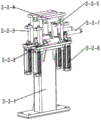
FIG. 5 is a schematic view of a milling unit according to the present invention;
FIG. 6 is a schematic view of a sawing unit according to the present invention;
FIG. 7 is a schematic view of a jaw discharge apparatus of the present invention;
FIG. 8 is a schematic structural view of a discharging unit of the present invention;
FIG. 9 is a schematic view of the overall structure of the present invention with a protective cover;
FIG. 10 is a schematic view of a part of the structure of the feeding unit of the present invention.
Detailed Description
In the following, the technical solutions in the embodiments of the present invention will be clearly and completely described with reference to the drawings provided in the embodiments of the present invention, and it is obvious that the described embodiments are only preferred embodiments of the present invention, and not all embodiments. All other embodiments, which can be derived by a person skilled in the art from the preferred embodiments of the invention without making any creative effort, shall fall within the protection scope of the invention. The present invention is described in further detail below.
In the description of the present invention, it is to be understood that the terms "upper", "lower", "top", "bottom", "inner", "outer", and the like, indicate orientations or positional relationships based on the orientations or positional relationships shown in the drawings. The foregoing definitions are provided merely to facilitate description and to simplify description and are not intended to indicate or imply that the structures referred to must have a particular orientation, be constructed and operated in a particular orientation and are not to be construed as limiting the invention.
As shown in fig. 1-10, the invention provides an aluminum profile milling and sawing combined machining center, which comprises a feeding unit 1, a milling and sawing main unit 2 and a discharging unit 3, wherein the milling and sawing main unit 2 comprises a front positioning and clamping device 2-2 for clamping a workpiece, a milling unit 2-3, a sawing unit 2-4 and a clamping jaw discharging device 2-5 for discharging, the front positioning and clamping device 2-2 is arranged behind the feeding unit 1 and is matched with the feeding unit 1 for use, and the clamping jaw discharging device 2-5 is arranged in front of the discharging unit 3 and is matched with the discharging unit 3 for use.
The automatic cutting machine is characterized in that chip removers 2-6 are further arranged on one side of the milling unit 2-3 and the saw cutting unit 2-4, the front positioning clamping device 2-2, the milling unit 2-3, the saw cutting unit 2-4 and the clamping jaw discharging device 2-5 are fixed above the host machine base 2-1, an opening for discharging is formed in the host machine base 2-1, and the starting end of the chip removers 2-6 is arranged below the opening of the host machine base 2-1.
And a workpiece front positioning device 1-7 for positioning and detecting the width, height and length of the workpiece.
The front positioning and clamping device 2-2 comprises a support 2-2-1 arranged above a main machine base 2-1, a horizontal supporting roller 2-2-2, a rear vertical roller 2-2-3, an upper pressure roller 2-2-4 and a side pressure roller 2-2-5 are arranged on the support 2-2-1 and used for clamping the upper surface, the lower surface, the front surface and the rear surface and ensuring continuous feeding, the upper pressure roller 2-2-4 is driven by an upper pressure cylinder 2-2-6, and the side pressure roller 2-2-5 is driven by a side pressure cylinder 2-2-7.
The milling unit 2-3 comprises milling columns 2-3-1, horizontal sliding plates 2-3-2 and vertical sliding plates 2-3-3 which are arranged in a layered mode, openings are formed in the center parts of the milling columns 2-3-1, a workpiece can penetrate through the openings, the milling columns 2-3-1 can move in the moving direction of the workpiece, the horizontal sliding plates 2-3-2 are arranged on the milling columns 2-3-1 and can move in the horizontal direction, the vertical sliding plates 2-3-3 are arranged on the horizontal sliding plates 2-3-2 and can move in the vertical direction, and the milling columns 2-3-1, the horizontal sliding plates 2-3-2, the milling columns 2-3-3, the horizontal sliding plates 2-3 and the vertical sliding plates 2-3 are driven by three sets of servo motors and the ball screws respectively, A vertical sliding plate 2-3-3), one end of the vertical sliding plate 2-3-3, which is close to the front positioning and clamping device 2-2, is provided with a plurality of small sliding plates 2-3-6, and the electric spindle 2-3-5 is arranged on the small sliding plates 2-3-6 and can be driven to move by an air cylinder.
6 small sliding plates 2-3-6 are arranged, 2 small sliding plates are symmetrically arranged in the vertical direction and 4 small sliding plates are symmetrically arranged in the horizontal direction, each small sliding plate 2-3-6 is provided with an electric spindle 2-3-5 driven by a cylinder to move, and the direction of an output shaft of each electric spindle 2-3-5 is towards the opening of the central part.
The sawing unit 2-4 comprises a 90-degree sawing electric spindle 2-4-8, a 45-degree sawing electric spindle 2-4-11 and a 135-degree sawing electric spindle 2-4-12, and saw blades for cutting are mounted on the sawing unit.
The 90-degree saw cutting electric spindle 2-4-8 is arranged on a straight cutting motor sliding plate 2-4-6, the straight cutting motor sliding plate 2-4-6 is arranged on a small sliding table 2-4-5 and can be driven to move through a pneumatic driving device 2-4-7, a small base 2-4-4 is further arranged below the 90-degree saw cutting electric spindle 2-4-8, a saw upright 2-4-1 is arranged on one side of the 90-degree saw cutting electric spindle 2-4-8, a sliding seat 2-4-2 capable of moving up and down is arranged on the saw upright 2-4-1, a saw cutting horizontal sliding plate 2-4-3 capable of moving horizontally is arranged on the sliding seat 2-4-2, and 45-degree saw cutting electric spindles 2-4-11 and a sliding seat 2-4-3 are arranged on the upper side and the lower side of the saw cutting horizontal sliding plate 2-4-3 respectively The automatic sawing machine is characterized in that a 135-degree sawing electric spindle 2-4-12 is arranged, the moving range of a sawing horizontal sliding plate 2-4-3 in the front-back direction of a sliding seat 2-4-2 (namely the direction perpendicular to the horizontal direction of workpiece transportation and close to a workpiece is the front, and the direction far away from the workpiece is the back) is 5 mm-10 mm (used for avoiding the processed workpiece), and a pre-sawing clamping device 2-4-9 and a kerf clamping device 2-4-10 are further sequentially arranged at the 45-degree sawing electric spindle 2-4-11 and the 135-degree sawing electric spindle 2-4-12 in the moving direction of the workpiece and used for fixing the workpiece.
The clamping jaw discharging device 2-5 comprises a discharging rack 2-5-1, the discharging rack 2-5-1 is connected with a small base 2-4-4, a movable discharging sliding plate 2-5-2 is arranged on the discharging rack 2-5-1, a servo device 2-5-4 for driving the discharging sliding plate 2-5-2 to move is arranged on the discharging sliding plate 2-5-2, and a clamping device 2-5-3 for clamping a saw cut of a workpiece is further arranged on the discharging sliding plate 2-5-2.
The discharging unit 3 comprises a base 3-1 and a plurality of rows of discharging synchronous belt mechanisms 3-4 arranged on the base 3-1, the discharging synchronous belt mechanisms 3-4 are driven by a speed reducing motor 3-3, a lifting material supporting roller device 2 is arranged at the starting end of each discharging synchronous belt mechanism 3-4 and used for receiving workpieces conveyed out by a clamping jaw discharging device 2-5, a marking positioning device 3-6 is arranged in the middle of each discharging synchronous belt mechanism 3-4, and an automatic marking and labeling device 3-5 matched with the marking positioning device 3-6 is arranged on one side of the marking positioning device 3-6.
The device use process is:
manually scanning and comparing the blank workpieces, confirming processing information and avoiding feeding errors; the method comprises the following steps that a workpiece is sequentially placed on a synchronous belt mechanism 1-4 with an end positioning device, a speed reduction motor 1-3 drives the synchronous belt mechanism 1-4 to rotate to a working position of an industrial camera detection device 1-8, image acquisition and visual comparison of section sections and section colors are carried out, feeding errors are avoided, then the workpiece continues to move forwards to a feeding position of an innermost feeding manipulator 1-2, a workpiece detection switch detects that the workpiece is in place, side material pressing parts of a workpiece upper material pressing device 1-6 and a lifting positioning roller device 1-5 complete detection of height and width of a blank, the feeding manipulator 1-2 moves forwards to push the blank workpiece to a workpiece front positioning device 1-7, detection of the length of the blank workpiece is completed, third-time feeding detection is completed, and feeding conditions are met; the control system instructs the feeding manipulator 1-2 to convey the blank workpiece to the processing start position, and the complete one-time feeding preparation action is completed. Then the workpiece is milled and sawn by the milling unit 2-3 and the sawing unit 2-4 in sequence, the processing process of the milling unit 2-3 is that after the workpiece reaches a proper processing position, the workpiece is respectively clamped or jointly clamped and fixed by the front positioning and clamping device 2-2 and the rear positioning and clamping device 2-3-7 (when the workpiece does not reach the position of the rear positioning and clamping device 2-3-7, the workpiece is separately clamped and fixed by the front positioning and clamping device 2-2, when the workpiece reaches the position of the rear positioning and clamping device 2-3-7, the workpiece is jointly fixed by the two devices, when the workpiece is far away from the front positioning and clamping device 2-2, the workpiece is separately fixed by the rear positioning and clamping device 2-3-7), then a plurality of output shafts of electric spindles 2-3-5 arranged on the milling unit 2-3 move, the hole milling drill bit arranged on the electric spindle is driven to mill holes, the electric spindle 2-3-5 can move in the axial direction of a three-axis coordinate system in the process, the position needing to be milled can be machined in a moving mode through the milling upright columns 2-3-1, the horizontal sliding plates 2-3-2 and the vertical sliding plates 2-3-3 which are arranged in multiple layers, the saw cutting machining process includes the steps that saw cutting machining of three angles is achieved through the 90-degree saw cutting electric spindle 2-4-8, the 45-degree saw cutting electric spindle 2-4-11 and the 135-degree saw cutting electric spindle 2-4-12, the 90-degree saw cutting electric spindle 2-4-8 moves transversely and conventional vertical cutting is conducted in consideration of the influence of the machining direction, and the 45-degree saw cutting electric spindle 2-4-11 and the 135-degree saw cutting electric spindle 2-4-12 are vertically lifted up and down The cutting is carried out in a descending moving mode, the saw cutting horizontal sliding plate 2-4-3 can move on the sliding seat 2-4-2 within the moving range of 5 mm-10 mm, further, a machined workpiece is avoided (the milling machining and the saw cutting machining processes are determined by the control device according to the actual position of the workpiece), after the process is finished, a finished workpiece is conveyed to the discharging unit 3 after the material clamping is carried out through the subsequent clamping jaw discharging device 2-5, then the marking and discharging processes are finished, and the whole machining process is finished to obtain a finished product.
Finally, the above embodiments are only for illustrating the technical solutions of the present invention and not for limiting, although the present invention has been described in detail with reference to the preferred embodiments, it should be understood by those skilled in the art that modifications or equivalent substitutions may be made to the technical solutions of the present invention without departing from the spirit and scope of the technical solutions of the present invention, and all of them should be covered in the claims of the present invention.
Claims (10)
1. The utility model provides an aluminium alloy mills saw combined machining center which characterized in that, includes the material loading unit, mills saw host computer unit and the unit of unloading, mill saw host computer unit including the preceding positioning and clamping device who is used for pressing from both sides tight work piece that sets gradually, mill the unit, saw cut the unit and be used for the clamping jaw discharging device of unloading, preceding positioning and clamping device sets up behind the material loading unit, uses with the material loading unit cooperation, clamping jaw discharging device sets up before the unit of unloading, uses with the unit cooperation of unloading.
2. The aluminum profile milling and sawing combined machining center according to claim 1, wherein a chip cleaner is further arranged on one side of the milling unit and the sawing unit, the front positioning and clamping device, the milling unit, the sawing unit and the clamping jaw discharging device are fixed above the main machine base, an opening for discharging is formed in the main machine base, and the starting end of the chip cleaner is arranged below the opening of the main machine base.
3. The aluminum profile milling and sawing combined machining center according to claim 1, wherein the feeding unit comprises a feeding base, a feeding manipulator is arranged on the feeding base, the feeding manipulator is arranged on a movable base, the movable base is arranged on a guide rail and can move in the workpiece moving direction, the feeding manipulator can move in the horizontal direction and the vertical direction perpendicular to the moving direction of the movable base to realize the axial movement of the feeding manipulator on three-axis coordinate axes, a synchronous belt mechanism perpendicular to the workpiece moving direction is further arranged above the feeding base and is driven by a speed reduction motor, the synchronous belt mechanisms are arranged side by side, an industrial camera detection device is further arranged on one side of the feeding unit close to the milling and sawing main unit, and a lifting positioning roller device is further arranged at the position of the synchronous belt mechanism, The workpiece pressing device and the workpiece front positioning device are used for positioning and detecting the width, height and length of the workpiece.
4. The aluminum profile milling and sawing combined machining center as claimed in claim 2, wherein the front positioning and clamping device comprises a support arranged above a base of the main machine, a horizontal supporting roller, a rear vertical roller, an upper nip roller and a side nip roller are arranged on the support and used for clamping the upper surface, the lower surface, the front surface and the rear surface and ensuring continuous feeding, the upper nip roller is driven by an upper nip cylinder, and the side nip roller is driven by a side nip cylinder.
5. The aluminum profile milling and sawing combined machining center according to claim 2, wherein the milling unit comprises milling columns, horizontal sliding plates and vertical sliding plates which are arranged in a layered mode, openings are formed in the center portions of the milling columns, a workpiece can penetrate through the openings, the milling columns can move in the moving direction of the workpiece, the horizontal sliding plates are arranged on the milling columns and can move in the horizontal direction, the vertical sliding plates are arranged on the horizontal sliding plates and can move in the vertical direction and are driven by servo motors and ball screws, a plurality of small sliding plates are arranged at one ends, close to the front positioning and clamping devices, of the vertical sliding plates, and electric spindles are arranged on the small sliding plates and can move through air cylinders.
6. The aluminum profile milling and sawing combined machining center according to claim 5, wherein the number of the small sliding plates is 6, namely 2 symmetrically arranged in the vertical direction and 4 symmetrically arranged in the horizontal direction, each small sliding plate is provided with an electric spindle driven by an air cylinder to move, and the output shafts of the electric spindles are all arranged towards the opening of the central portion.
7. The aluminum profile milling and sawing combined machining center as claimed in claim 2, wherein the sawing units comprise 90 ° sawing electric spindles, 45 ° sawing electric spindles and 135 ° sawing electric spindles, and are all provided with saw blades for cutting.
8. The aluminum profile milling and sawing combined machining center is characterized in that the 90-degree sawing electric spindle is arranged on a straight-cutting motor sliding plate, the straight-cutting motor sliding plate is arranged on a small sliding table and can move through the driving of a pneumatic driving device, a small base is further arranged below the 90-degree sawing electric spindle, a sawing upright post is arranged on one side of the 90-degree sawing electric spindle, a sliding seat capable of moving up and down is arranged on the sawing upright post, a sawing horizontal sliding plate capable of moving horizontally is arranged on the sliding seat, the 45-degree sawing electric spindle and the 135-degree sawing electric spindle are respectively arranged on the upper side and the lower side of the sawing horizontal sliding plate, the front and back movement range of the sawing horizontal sliding plate on the sliding seat is 5 mm-10 mm, the 45-degree sawing electric spindle and the 135-degree sawing electric spindle are sequentially provided with a pre-sawing clamping device and a sawing port clamping device from the movement direction of a workpiece, for fixing the workpiece.
9. The aluminum profile milling and sawing combined machining center according to claim 2, wherein the clamping jaw discharging device comprises a discharging rack and a small base, a movable discharging sliding plate is arranged on the discharging rack, a servo device for driving the discharging sliding plate to move is arranged on the discharging sliding plate, and a saw cut rear clamping device for clamping a workpiece is further arranged on the discharging sliding plate.
10. The aluminum profile milling and sawing combined machining center according to claim 1 is characterized in that the unloading unit comprises a base and a plurality of rows of unloading synchronous belt mechanisms arranged on the base, the unloading synchronous belt mechanisms are driven by speed reduction motors, a lifting material supporting roller device is arranged at the starting end of each unloading synchronous belt mechanism and used for receiving workpieces conveyed out by a clamping jaw discharging device, a marking positioning device is arranged in the middle of each unloading synchronous belt mechanism, and an automatic marking and labeling device matched with the marking positioning device is arranged on one side of each marking positioning device.
Priority Applications (1)
| Application Number | Priority Date | Filing Date | Title |
|---|---|---|---|
| CN202111191051.3A CN113787346A (en) | 2021-10-13 | 2021-10-13 | Aluminum profile milling and sawing combined machining center |
Applications Claiming Priority (1)
| Application Number | Priority Date | Filing Date | Title |
|---|---|---|---|
| CN202111191051.3A CN113787346A (en) | 2021-10-13 | 2021-10-13 | Aluminum profile milling and sawing combined machining center |
Publications (1)
| Publication Number | Publication Date |
|---|---|
| CN113787346A true CN113787346A (en) | 2021-12-14 |
Family
ID=79184835
Family Applications (1)
| Application Number | Title | Priority Date | Filing Date |
|---|---|---|---|
| CN202111191051.3A Pending CN113787346A (en) | 2021-10-13 | 2021-10-13 | Aluminum profile milling and sawing combined machining center |
Country Status (1)
| Country | Link |
|---|---|
| CN (1) | CN113787346A (en) |
Cited By (1)
| Publication number | Priority date | Publication date | Assignee | Title |
|---|---|---|---|---|
| CN115464331A (en) * | 2022-10-21 | 2022-12-13 | 广东博高智能装备系统有限公司 | Section cutting processing method |
-
2021
- 2021-10-13 CN CN202111191051.3A patent/CN113787346A/en active Pending
Cited By (1)
| Publication number | Priority date | Publication date | Assignee | Title |
|---|---|---|---|---|
| CN115464331A (en) * | 2022-10-21 | 2022-12-13 | 广东博高智能装备系统有限公司 | Section cutting processing method |
Similar Documents
| Publication | Publication Date | Title |
|---|---|---|
| CN202045389U (en) | Improved edge milling machine for automobile steel plate springs | |
| CN113478235A (en) | Efficient processing production line and processing method for door and window profiles | |
| US20110126681A1 (en) | Method for severing a protruding portion of a layer of a laminate | |
| CN108188756B (en) | Glass window section bar preprocessing system | |
| CN113814744A (en) | Drilling, milling and scribing combined machining center for door and window aluminum profiles | |
| CN212793912U (en) | Aluminum profile processing production line | |
| CN113787346A (en) | Aluminum profile milling and sawing combined machining center | |
| CN201079849Y (en) | Multi-station rotary automatic drilling machine | |
| CN113305577A (en) | Numerical control section end face milling center | |
| CN216730548U (en) | Aluminum profile milling and sawing combined machining center | |
| CN204621186U (en) | Horizontal-vertical double-purpose high-speed machine tool | |
| CN218426860U (en) | Full-function composite production line for aluminum doors and windows | |
| CN206747982U (en) | A kind of rolled thread is to the side's of punching automatic production line | |
| CN210453075U (en) | Novel high-efficient numerical control cutting machine | |
| CN209849954U (en) | Automatic tool setting automatic processing plane finish milling machine tool | |
| CN210615745U (en) | Grooving device and aluminum plate cutting grooving machine with same | |
| CN211161561U (en) | High-efficient group angle machine of aluminium door and window hydraulic pressure | |
| CN110977493A (en) | Manufacturing process of multi-robot cooperation lock panel | |
| CN216178348U (en) | Drilling, milling and scribing combined machining center for door and window aluminum profiles | |
| CN219402037U (en) | Automatic pipe fitting turning equipment | |
| CN206296503U (en) | A kind of multifunctional milling machine | |
| CN219188884U (en) | Oil removal detection equipment for pipe fitting | |
| CN217167416U (en) | Efficient processing production line for door and window profiles | |
| CN219093757U (en) | Drilling and milling machine tool capable of automatically and simultaneously machining multiple stations | |
| CN216463141U (en) | A insert mould processing frock for sufficient roller frame |
Legal Events
| Date | Code | Title | Description |
|---|---|---|---|
| PB01 | Publication | ||
| PB01 | Publication | ||
| SE01 | Entry into force of request for substantive examination | ||
| SE01 | Entry into force of request for substantive examination |