CN113756496B - Structure and construction method of small-space floor bearing plate under roof reverse-procedure construction - Google Patents
Structure and construction method of small-space floor bearing plate under roof reverse-procedure construction Download PDFInfo
- Publication number
- CN113756496B CN113756496B CN202111091705.5A CN202111091705A CN113756496B CN 113756496 B CN113756496 B CN 113756496B CN 202111091705 A CN202111091705 A CN 202111091705A CN 113756496 B CN113756496 B CN 113756496B
- Authority
- CN
- China
- Prior art keywords
- floor
- support plate
- steel bar
- bar truss
- bearing plate
- Prior art date
- Legal status (The legal status is an assumption and is not a legal conclusion. Google has not performed a legal analysis and makes no representation as to the accuracy of the status listed.)
- Active
Links
Images


Classifications
-
- E—FIXED CONSTRUCTIONS
- E04—BUILDING
- E04B—GENERAL BUILDING CONSTRUCTIONS; WALLS, e.g. PARTITIONS; ROOFS; FLOORS; CEILINGS; INSULATION OR OTHER PROTECTION OF BUILDINGS
- E04B5/00—Floors; Floor construction with regard to insulation; Connections specially adapted therefor
- E04B5/16—Load-carrying floor structures wholly or partly cast or similarly formed in situ
- E04B5/17—Floor structures partly formed in situ
-
- E—FIXED CONSTRUCTIONS
- E04—BUILDING
- E04G—SCAFFOLDING; FORMS; SHUTTERING; BUILDING IMPLEMENTS OR AIDS, OR THEIR USE; HANDLING BUILDING MATERIALS ON THE SITE; REPAIRING, BREAKING-UP OR OTHER WORK ON EXISTING BUILDINGS
- E04G21/00—Preparing, conveying, or working-up building materials or building elements in situ; Other devices or measures for constructional work
- E04G21/02—Conveying or working-up concrete or similar masses able to be heaped or cast
-
- E—FIXED CONSTRUCTIONS
- E04—BUILDING
- E04G—SCAFFOLDING; FORMS; SHUTTERING; BUILDING IMPLEMENTS OR AIDS, OR THEIR USE; HANDLING BUILDING MATERIALS ON THE SITE; REPAIRING, BREAKING-UP OR OTHER WORK ON EXISTING BUILDINGS
- E04G21/00—Preparing, conveying, or working-up building materials or building elements in situ; Other devices or measures for constructional work
- E04G21/14—Conveying or assembling building elements
-
- E—FIXED CONSTRUCTIONS
- E04—BUILDING
- E04B—GENERAL BUILDING CONSTRUCTIONS; WALLS, e.g. PARTITIONS; ROOFS; FLOORS; CEILINGS; INSULATION OR OTHER PROTECTION OF BUILDINGS
- E04B5/00—Floors; Floor construction with regard to insulation; Connections specially adapted therefor
- E04B5/16—Load-carrying floor structures wholly or partly cast or similarly formed in situ
- E04B5/17—Floor structures partly formed in situ
- E04B2005/176—Floor structures partly formed in situ with peripheral anchors or supports
Abstract
The invention provides a structure and a construction method of a small-space floor bearing plate under roof reverse process construction, which comprises the following steps: the shear wall, the support wall and the steel bar truss floor support plate are characterized in that floor support plate side sealing pieces are arranged on the side faces of the steel bar truss floor support plate, a plurality of locking rods are arranged on the side faces of the floor support plate side sealing pieces, floor support plate sealing mechanisms are arranged on the outer side faces of the two oppositely arranged floor support plate side sealing pieces, and the locking rods are used for fixing the floor support plate sealing mechanisms; floor carrier plate seals pressure mechanism includes: the construction method and the structure of the invention well overcome the inconvenience brought by a formwork supporting system, and have the advantages of strong field construction operability, easy implementation and complete integral forming structure. The method is suitable for floors with the clear height of small-space floors which is too low to meet the requirement of installing a formwork system, overcomes the problems of difficult formwork installation, insufficient operation space, long construction period, incapability of formwork removal and the like, and can reduce the construction difficulty so as to shorten the construction period.
Description
Technical Field
The invention belongs to the field of construction, and particularly relates to a structure and a construction method of a small-space floor support plate under roof reverse-procedure construction.
Background
The mechanical property of the steel bar truss floor bearing plate is basically the same as that of the traditional cast-in-place floor slab, and the steel bar truss floor bearing plate is widely applied to the construction of various buildings.
Based on the above description, the present inventors found that the structure and the construction method of the existing small-space floor support plate under roof reverse process construction mainly have the following disadvantages, for example:
to the structure that the clear height of floor was crossed lowly and can not satisfy the formwork requirement in the little space, because the clear height of floor is only 1.4m in the little space, has been less than adult's normal construction operation height, causes the site operation difficult, and the unable form removal in later stage for the construction increases the degree of difficulty, and construction cycle extension, and very easily influences structure shaping quality.
Disclosure of Invention
In order to solve the technical problems, the invention provides a structure and a construction method of a small-space floor support plate under roof reverse-procedure construction, and aims to solve the existing problems.
Aiming at the defects of the prior art, the invention discloses a structure of a small-space floor bearing plate under roof reverse process construction and a construction method thereof, and aims and effects of the structure and the construction method are achieved by the following specific technical means: the utility model provides a structure of little space building carrier plate under roofing reverse process construction, includes: the shear wall, the support wall and the steel bar truss floor support plate are characterized in that floor support plate side sealing pieces are arranged on the side faces of the steel bar truss floor support plate, a plurality of locking rods are arranged on the side faces of the floor support plate side sealing pieces, floor support plate sealing mechanisms are arranged on the outer side faces of the two oppositely arranged floor support plate side sealing pieces, and the locking rods are used for fixing the floor support plate sealing mechanisms; floor carrier plate seals pressure mechanism includes: the laminating is in the last stay in the rotatory setting in the side of the building carrier plate side cover piece, the inside traction area that sets up of end stay, two the traction area tail end can be the nestification and connect together, inside the side embedding of traction area is pasted the piece, and transversely runs through in the end stay, the laminating of end stay sets up in steel bar truss building carrier plate below.
Compared with the prior art, the invention has the following advantagesAdvantageous effects:
The construction method adopts the construction of the steel bar truss floor bearing plate, the floor bearing plate side sealing piece on the side surface of the steel bar truss floor bearing plate is sealed and pressed through the floor bearing plate sealing and pressing mechanism, so that a stable mold cavity is formed inside, when the bottom stay bar is adjusted to be slightly larger than the length of the steel bar truss floor bearing plate, when the pressing piece is attached to the floor bearing plate side sealing piece, the traction belt is used for drawing outwards and pressing, so that the bottom stay bar can be shortened, the pressing piece is in a pressing state towards the floor bearing plate side sealing piece, after the two groups of different traction belts are buckled, the traction belts are matched with the locking rods on the side surface of the floor bearing plate side sealing piece for final fixing, and when the mold is removed, only the traction belts need to be released, so that other mold supporting parts can be easily removed.
The construction method and the structure of the invention well overcome the inconvenience brought by a formwork system, and the construction method and the structure have strong operability, easy implementation and complete integral forming structure. The method is suitable for floors with the clear height of small-space floors which is too low and cannot meet the installation requirements of the formwork supporting system, overcomes the problems of difficult formwork installation, insufficient operation space, long construction period, incapability of formwork removal and the like, and can reduce the construction difficulty, thereby shortening the construction period.
Drawings
Fig. 1 is a schematic structural diagram of a small-space floor support plate under roof reverse construction.
Fig. 2 is a schematic side view and a half-section structure of a small-space floor support plate under roof reverse construction.
Fig. 3 is a side view of a half-section structure of the floor covering plate pressing mechanism.
Fig. 4 is a side view of the floor covering plate pressing mechanism.
FIG. 5 is a schematic side view of a wafer.
Fig. 6 is a front view of the teeth.
In the figure: the steel bar truss floor support plate comprises a shear wall-1, a support wall-2, floor support plate side sealing pieces-3, a floor support plate sealing and pressing mechanism-4, L-shaped equilateral angle steel-5 and a steel bar truss floor support plate-6;
a sticking sheet-41, a bottom bracing strip-42 and a traction belt-43;
a tooth-411, a side groove-412, a guide vane-413 and a connecting sleeve-414;
a first sleeve connecting rod-421, a folding sleeve-422 and a second sleeve connecting rod-423;
collar-431, lock-432;
a locking bar-31.
Detailed Description
Embodiments of the present invention will be described in further detail with reference to the drawings and examples. The following examples are intended to illustrate the invention but are not intended to limit the scope of the invention.
In the description of the present invention, "a plurality" means two or more unless otherwise specified; the terms "upper", "lower", "left", "right", "inner", "outer", "front", "rear", "head", "tail", and the like, indicate orientations or positional relationships based on the orientations or positional relationships shown in the drawings, are merely for convenience in describing the present invention and to simplify the description, and do not indicate or imply that the device or element referred to must have a particular orientation, be constructed in a particular orientation, and be operated, and thus, should not be construed as limiting the present invention. Furthermore, the terms "first," "second," "third," and the like are used for descriptive purposes only and are not to be construed as indicating or implying relative importance.
In the description of the present invention, it should be noted that, unless explicitly stated or limited otherwise, the terms "connected" and "connected" are to be interpreted broadly, e.g., as being fixed or detachable or integrally connected; can be mechanically or electrically connected; may be directly connected or indirectly connected through an intermediate. The specific meanings of the above terms in the present invention can be understood in specific cases to those skilled in the art.
Examples
As shown in figures 1-3:
the invention provides a structure of a small-space floor bearing plate under roof reverse process construction, which comprises the following components: the shear wall 1, the support wall 2 and the steel bar truss floor support plate 6 are characterized in that a floor support plate side sealing piece 3 is arranged on the side surface of the steel bar truss floor support plate 6, a plurality of locking rods 31 are arranged on the side surface of the floor support plate side sealing piece 3, floor support plate sealing mechanisms 4 are arranged on the outer side surfaces of the two oppositely-arranged floor support plate side sealing pieces 3, and the locking rods 31 are used for fixing the floor support plate sealing mechanisms 4; the floor support plate pressure sealing mechanism 4 includes: the laminating is in the laminating of the laminating piece 41 in the building carrier plate side envelope 3 outside, the rotatory end stay 42 that sets up in laminating piece 41 side, the inside traction area 43 that sets up of end stay 42, two the traction area 43 tail end can be the nestification and connect together, inside the embedding laminating piece 41 of traction area 43 side, and transversely run through in end stay 42, end stay 42 laminating sets up in steel bar truss building carrier plate 6 below.
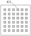
As shown in fig. 5: the side surface of the pressing sheet 41 is provided with a curved side groove 412, the groove of the side groove is deep to the middle section of the pressing sheet 41, a traction belt 43 is embedded in the side groove, a biting tooth 411 is arranged above the inner side surface of the pressing sheet 41, the biting tooth 411 is embedded and pressed on the outer side surface of the floor panel side sealing sheet 3, a guide piece 413 is fixedly arranged below the inner side surface of the pressing sheet 41, a connecting sleeve 414 is rotatably arranged below the inner side surface of the pressing sheet 41, the guide piece 413 is rotatably embedded in the connecting sleeve 414, and the traction belt 43 is embedded in the pressing sheet 41 through the side groove 412 during assembly. Wherein, the inside side groove 412 of laminating piece 41 is through the concatenation of two arc wall structures, and the degree of depth in groove is for laminating the half of 41 lateral length, and top arc radius is great, and degree of curvature is comparatively mild, and below arc radius is less, and degree of curvature is great, through this setting, can make outside pulling take 43 time more light, and make the condition of putting back fast to be difficult to appear in the traction area 43.
Furthermore, the teeth 411 on the side surface of the pressing sheet 41 are arranged in a matrix, when fixing is needed, the pressing sheet 41 is adhered to the side sealing sheet 3 of the floor support plate, and the matrix teeth 411 can be embedded and pressed on the side sealing sheet 3 of the floor support plate to be fixed through the constraint of the traction belt 43; when the connecting sleeve 414 is detached, the whole pressing piece 41 is unfolded by rotating the pressing piece 41 around a pin below the connecting sleeve 414, and the unfolded pressing piece 41 is used as a handle to detach the whole. Wherein, the tooth 411 when contacting with building carrier plate side sealing 3, when receiving side pulling force, can provide stronger resisting force for pasting the pressure sheet 41 through the part that tooth 411 imbeds in building carrier plate side sealing 3, and then can keep original state when the side receives external force.
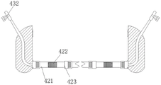
As shown in fig. 4: the bottom stay 42 comprises a first extension rod 421, a folding sleeve 422 and a second extension rod 423, wherein a thread groove is formed in one side of the first extension rod 421, a thread rod is arranged on one side of the second extension rod 423, the folding sleeve 423 is arranged between the first extension rod 421 and the second extension rod 423, a telescopic rod 424 is arranged inside the folding sleeve 423, the telescopic rod 424 is arranged in the middle of the first extension rod 421 and the second extension rod 422, and the thread groove in the first extension rod 421 is in threaded connection with the thread rod in the second extension rod 423. The folding sleeve 423 mainly blocks concrete falling down in the construction process, and in the folding process, the rubber material is adopted, so that the attached concrete can be removed, and the inner telescopic rod 424 is protected.
Further, the bottom stay 42 is composed of a plurality of groups of first extension rods 421, folding sleeves 422 and second extension rods 423, in other embodiments, the actual groups of the first extension rods 421, the folding sleeves 422 and the second extension rods 423 are correspondingly arranged according to the actual length of the steel bar truss floor slab 6, and can be adjusted according to actual requirements.
As shown in fig. 3: the tail end of the traction belt 43 is provided with a lantern ring 431, the tail end of the traction belt 43 is provided with a locking part 432, and the locking part 432 is movably embedded in the lantern ring 431.
Further, a conical groove is formed in the lantern ring 431, the locking piece 432 is provided with a stepped rod, a through groove is formed in the rod, the attaching pressing piece 41 is attached to the floor bearing plate side sealing piece 3, after the traction belt 43 completes traction operation, the locking piece 432 can be embedded into the lantern ring 431 to be fixed, and the locking piece 432 is inserted into the locking rod 31 on the side face of the floor bearing plate side sealing piece 3 to be fixed.
As shown in fig. 2: a steel bar truss floor bearing plate 6 is arranged above the supporting wall 2, the side face of the steel bar truss floor bearing plate 6 is vertically attached to the shear wall 1, double-layer bidirectional steel bars are arranged inside the steel bar truss floor bearing plate 6, preset steel bars in the shear wall 1 comprise first steel bars and second steel bars, the first steel bars are L-shaped, the preset length in the shear wall 1 is more than or equal to 5d, and at least the preset length reaches the central line of the shear wall 1; the tail part of the second steel bar is provided with a hook, the preset length in the shear wall 1 is not less than 5d, and the length is less than that of the first steel bar. Wherein, the floor on 1 limit of shear force wall can select for use two kinds of construction methods: firstly, when reinforcing steel bars can be reserved, a method of reserving the reinforcing steel bars at the connecting part of a floor slab and the shear wall 1 is adopted; secondly, when reinforcing steel bars cannot be reserved, during secondary construction of the floor slab, a method of planting reinforcing steel bars at the joint of the floor slab and the shear wall 1 is adopted, the reinforcing steel bars of the floor slab are planted in the shear wall 1, and the planting depth is 180 mm; in this embodiment, a first type of pre-cut reinforcement is selected, and in other embodiments, a second type of non-pre-cut reinforcement is selected.
In this embodiment, since the small space floor area is divided into the pool area and the non-pool area, the small space floor area in this embodiment belongs to the pool area, and the support walls 2 belonging to the pool area and the support walls 2 are concrete support walls 2; in other embodiments, non-pool areas are constructed using mortar-brick concrete in combination with the support walls 2, the brick-concrete structure support walls 2 spanning no more than 4 m. Wherein the thickness of the swimming pool area of the floor bearing plate is 220mm, the model of the floor bearing plate adopts TD7-190-600, the thickness of the non-swimming pool area is 120m, and the model of the floor bearing plate adopts TD 3-90-576; double-layer bidirectional phi 12@200 and phi 8@200 steel bars are respectively arranged in a steel bar mesh frame of the steel bar truss floor bearing plate 6 and are pulled through and laid, and gluten extends to at least 1m of an adjacent plate; the number of the floor bearing plate is TD7-190-600, the height of the truss is 190mm, the maximum applicable span of the plate simply supported in the construction stage is 3.6m, and the maximum applicable span of the plate continuously is 3.0 m; the model TD3-90-576, the truss height 90mm, the simply supported maximum applicable span of the plate at the construction stage 3.0m, and the continuous maximum applicable span of the plate 3.4 m.
As further improvement, draw through in the steel bar truss building carrier plate 6 and lay and be equipped with double-deck two-way reinforcing bar, and the gluten stretches out adjacent board 1m at least, steel bar truss building carrier plate adopts die block steel sheet back-off and 2 fixed connection of knee wall, steel bar truss building carrier plate and 1 junction of shear force wall are provided with a plurality of L type equilateral angle steel 5. And angle steel is additionally arranged at the included angle position where the steel bar truss floor bearing plate 6 is contacted with the periphery of the support wall 2, and the angle steel is used for adjusting the levelness of the plate surface and preventing slurry leakage.
Furthermore, the L-shaped equilateral angle steel 5 has the size of 50mm multiplied by 5mm, is reinforced by anchors, and is arranged at every 200mm, wherein the L-shaped equilateral angle steel 5 is arranged; wherein, 6600mm is no less than 3L-shaped equilateral angle steels 5 for each steel bar truss floor bearing plate.
The steel bar truss floor support plate 6 is adopted for construction, and can be quickly built on site through preprocessing, so that the binding amount of the steel bars on site is reduced by 60-70%, the construction period can be further shortened, the construction operation is convenient, temporary support for construction can be greatly reduced or not needed, and the bottom surface of the floor slab does not need to be polished and repaired after the construction is finished; the steel bar truss floor bearing plate 6 is adopted for construction, the truss stress mode is reasonable, the material selection is economical, the comprehensive cost advantage is obvious, and the truss height and the steel bar diameter can be adjusted according to the actual span on site; the steel bar truss floor support plate 6 is adopted for construction, the mechanical property of the floor is basically the same as that of a traditional cast-in-place floor, the floor has good crack resistance, the fire resistance is equivalent to that of the traditional cast-in-place floor, and the floor is safe and reliable; adopt steel bar truss building carrier plate 6 construction, the reinforcing bar is arranged evenly, and upper and lower floor's reinforcing bar interval and concrete protective layer thickness have reliable assurance, and the two-way rigidity of floor is close, is favorable to the building antidetonation, and the quality guarantees more easily that the quality is guaranteed
A construction method of a small-space floor bearing plate under roof reverse process construction comprises the following steps:
s1, pre-arranging steel bars on the side surface of the shear wall 1;
s2, constructing the support wall 2 adjacent to the shear wall 1 to a preset height, and presetting reinforcing steel bars at the top of the support wall 2;
s3, vertically attaching one end of a prefabricated steel bar truss floor support plate 6 to a shear wall 1, transversely paving the prefabricated steel bar truss floor support plate above a support wall 2, and inserting reserved steel bars in the support wall 2 and the shear wall 1 into the prefabricated steel bar truss floor support plate 6;
s4, attaching the floor bearing plate side sealing piece 3 to the side surface of the steel bar truss floor bearing plate 6, and locking and fixing the steel bar truss floor bearing plate 6 through the floor bearing plate sealing and pressing mechanism 4;
s5, connecting the prefabricated steel bar truss floor bearing plate and the support wall 2 into a whole by pouring concrete to form a plate surface;
and S6, after the concrete is solidified, removing the side sealing sheet 3 of the floor bearing plate by releasing the floor bearing plate sealing and pressing mechanism 4.
In step S1, the roof deck structure is constructed first, and after the reinforcing bars are preset on the side face of the shear wall 1, the steel bars are returned to the floor slab on the lower layer of the roof for construction.
In step S2, the preset height of the supporting wall 2 is equal to the height of the roof slab — the height of the steel bar truss floor slab 6; and the length of the reserved steel bars above the support wall 2 is not more than the height of the steel bar truss floor bearing plate 6.
In step S4, the floor support plate sealing mechanism 4 attaches the two attaching pressing pieces 41 to the outer side of the floor support plate side sealing piece 3, attaches the bottom stay 42 to the bottom surface of the steel bar truss floor support plate 6, attaches the floor support plate side sealing piece 3 and the steel bar truss floor support plate 6 more tightly by pulling the traction belt 43 and the attaching pressing pieces 41 and the bottom stay 42, and locks the floor support plate side sealing piece 3 by fastening the collar 431 and the lock 432 together and then sleeving the locking rod 31 on the side of the floor support plate side sealing piece 3.
The embodiments of the present invention have been presented for purposes of illustration and description, and are not intended to be exhaustive or limited to the invention in the form disclosed. Many modifications and variations will be apparent to those of ordinary skill in the art. The embodiment was chosen and described in order to best explain the principles of the invention and the practical application, and to enable others of ordinary skill in the art to understand the invention for various embodiments with various modifications as are suited to the particular use contemplated.
Claims (9)
1. The utility model provides a structure of little space floor carrier plate under reverse process construction of roofing, includes: the shear wall, the support wall and the steel bar truss floor support plate are characterized in that floor support plate side sealing pieces are arranged on the side faces of the steel bar truss floor support plate, a plurality of locking rods are arranged on the side faces of the floor support plate side sealing pieces, floor support plate sealing mechanisms are arranged on the outer side faces of the two oppositely arranged floor support plate side sealing pieces, and the locking rods are used for fixing the floor support plate sealing mechanisms;
floor carrier plate seals pressure mechanism includes: the laminating is in the last stay of the building carrier plate side seal piece outside, the rotatory end stay that sets up of end stay side, the inside traction area that sets up of end stay, two the traction area tail end can the nested connection together, inside traction area side embedding paster, and transversely run through in the end stay, the laminating of end stay sets up in steel bar truss building carrier plate below.
2. The structure of the small-space floor bearing plate under the roof reverse process construction according to claim 1, characterized in that: the side of the attaching pressing piece is provided with a bent side groove, the groove of the side groove is deep to the middle section of the attaching pressing piece, a traction belt is embedded inside the attaching pressing piece, an engaging tooth is arranged above the inner side of the attaching pressing piece, the engaging tooth is embedded and pressed on the outer side surface of the side sealing piece of the floor bearing plate, a guide piece is fixedly arranged below the inner side of the attaching pressing piece, a connecting sleeve is rotatably arranged below the inner side of the attaching pressing piece, and the guide piece is rotatably embedded into the connecting sleeve.
3. The structure of the small-space floor bearing plate under the roof reverse process construction according to claim 1, characterized in that: the bottom stay comprises a first extension rod, a folding sleeve and a second extension rod, wherein a threaded groove is formed in one side of the first extension rod, a threaded rod is arranged on one side of the second extension rod, the folding sleeve is arranged between the first extension rod and the second extension rod, a telescopic rod is arranged in the folding sleeve, the telescopic rod is arranged in the middle of the first extension rod and the second extension rod, and the threaded groove in the first extension rod is in threaded connection with the threaded rod on the second extension rod.
4. The structure of the floor bearing plate in the small space under the roof reverse process construction according to claim 1, characterized in that: the traction belt tail end is provided with a lantern ring, the traction belt tail end is provided with a locking piece, and the locking piece is movably embedded in the lantern ring.
5. The structure of the small-space floor bearing plate under the roof reverse process construction according to claim 1, characterized in that: a steel bar truss floor bearing plate is arranged above the support wall, the side face of the steel bar truss floor bearing plate is vertically attached to the shear wall, double layers of bidirectional steel bars are arranged inside the steel bar truss floor bearing plate, preset steel bars in the shear wall comprise first steel bars and second steel bars, the first steel bars are L-shaped, the preset length in the shear wall is more than or equal to 5d, and at least the preset length reaches the center line of the shear wall; the tail part of the second steel bar is provided with a hook, the preset length in the shear wall is not less than 5d, and the length is less than that of the first steel bar.
6. The structure of the floor bearing plate in the small space under the roof reverse process construction according to claim 1, characterized in that: two-way reinforcing bar of double-deck is laid in pulling through in the steel bar truss building carrier plate, and the gluten stretches out adjacent board 1m at least.
7. The structure of the floor bearing plate in the small space under the roof reverse process construction according to claim 1, characterized in that: the steel bar truss floor support plate is fixedly connected with the supporting wall through bottom die steel plate reverse buckles.
8. The structure of the floor bearing plate in the small space under the roof reverse process construction according to claim 1, characterized in that: and a plurality of L-shaped equal-angle steels are arranged at the joint of the steel bar truss floor bearing plate and the shear wall.
9. The construction method of the small-space floor deck plate under the roof reverse process construction according to any one of claims 1 to 8, comprising the following steps:
s1, pre-arranging steel bars on the side surface of the shear wall;
s2, constructing the support wall adjacent to the shear wall to a preset height, and presetting reinforcing steel bars on the top of the support wall;
s3, vertically attaching one end of the prefabricated steel bar truss floor support plate to a shear wall, transversely paving the prefabricated steel bar truss floor support plate above a support wall, and inserting the reserved steel bars in the support wall and the shear wall into the prefabricated steel bar truss floor support plate;
s4, attaching a floor support plate side sealing piece to the side face of the steel bar truss floor support plate, and locking and fixing the steel bar truss floor support plate through a floor support plate sealing and pressing mechanism;
s5, connecting the prefabricated steel bar truss floor bearing plate and the support wall into a whole by pouring concrete to form a plate surface;
and S6, after the concrete is solidified, removing the floor bearing plate side sealing sheet by releasing the floor bearing plate sealing and pressing mechanism.
Priority Applications (1)
| Application Number | Priority Date | Filing Date | Title |
|---|---|---|---|
| CN202111091705.5A CN113756496B (en) | 2021-09-17 | 2021-09-17 | Structure and construction method of small-space floor bearing plate under roof reverse-procedure construction |
Applications Claiming Priority (1)
| Application Number | Priority Date | Filing Date | Title |
|---|---|---|---|
| CN202111091705.5A CN113756496B (en) | 2021-09-17 | 2021-09-17 | Structure and construction method of small-space floor bearing plate under roof reverse-procedure construction |
Publications (2)
| Publication Number | Publication Date |
|---|---|
| CN113756496A CN113756496A (en) | 2021-12-07 |
| CN113756496B true CN113756496B (en) | 2022-08-19 |
Family
ID=78796185
Family Applications (1)
| Application Number | Title | Priority Date | Filing Date |
|---|---|---|---|
| CN202111091705.5A Active CN113756496B (en) | 2021-09-17 | 2021-09-17 | Structure and construction method of small-space floor bearing plate under roof reverse-procedure construction |
Country Status (1)
| Country | Link |
|---|---|
| CN (1) | CN113756496B (en) |
Citations (10)
| Publication number | Priority date | Publication date | Assignee | Title |
|---|---|---|---|---|
| CA2515662A1 (en) * | 2004-11-05 | 2006-05-05 | Swa Holding Company, Inc. | Pre-cast concrete wall with truss ledge |
| CN107053440A (en) * | 2017-05-10 | 2017-08-18 | 中国十七冶集团有限公司 | A kind of precast plate girder pedestal preparation method |
| CN108385904A (en) * | 2018-04-25 | 2018-08-10 | 中铁第四勘察设计院集团有限公司 | A kind of parapet of roofing and its construction method |
| CN209413281U (en) * | 2018-08-31 | 2019-09-20 | 天津洪晟基业建材有限公司 | A kind of formwork being readily disassembled |
| CN110509411A (en) * | 2019-08-21 | 2019-11-29 | 南京唐壹信息科技有限公司 | A kind of detachable concreting mold of assembled architecture |
| CN110616838A (en) * | 2019-09-30 | 2019-12-27 | 甘肃建投科技研发有限公司 | Assembled composite floor slab with height limiting device and production process thereof |
| CN210013473U (en) * | 2019-04-26 | 2020-02-04 | 郑州一建集团有限公司 | Inverted L-shaped side form reinforcing structure |
| CN212248841U (en) * | 2020-02-27 | 2020-12-29 | 贵州建工集团第三建筑工程有限责任公司 | Connecting structure of reinforced truss concrete combined floor slab and concrete wall or beam |
| CN112502335A (en) * | 2020-12-09 | 2021-03-16 | 五冶集团上海有限公司 | Construction method of assembled building laminated slab |
| CN212866536U (en) * | 2020-04-08 | 2021-04-02 | 菏泽城建工程发展集团有限公司 | Concrete wall department steel bar truss floor carrier plate side supporting device |
-
2021
- 2021-09-17 CN CN202111091705.5A patent/CN113756496B/en active Active
Patent Citations (10)
| Publication number | Priority date | Publication date | Assignee | Title |
|---|---|---|---|---|
| CA2515662A1 (en) * | 2004-11-05 | 2006-05-05 | Swa Holding Company, Inc. | Pre-cast concrete wall with truss ledge |
| CN107053440A (en) * | 2017-05-10 | 2017-08-18 | 中国十七冶集团有限公司 | A kind of precast plate girder pedestal preparation method |
| CN108385904A (en) * | 2018-04-25 | 2018-08-10 | 中铁第四勘察设计院集团有限公司 | A kind of parapet of roofing and its construction method |
| CN209413281U (en) * | 2018-08-31 | 2019-09-20 | 天津洪晟基业建材有限公司 | A kind of formwork being readily disassembled |
| CN210013473U (en) * | 2019-04-26 | 2020-02-04 | 郑州一建集团有限公司 | Inverted L-shaped side form reinforcing structure |
| CN110509411A (en) * | 2019-08-21 | 2019-11-29 | 南京唐壹信息科技有限公司 | A kind of detachable concreting mold of assembled architecture |
| CN110616838A (en) * | 2019-09-30 | 2019-12-27 | 甘肃建投科技研发有限公司 | Assembled composite floor slab with height limiting device and production process thereof |
| CN212248841U (en) * | 2020-02-27 | 2020-12-29 | 贵州建工集团第三建筑工程有限责任公司 | Connecting structure of reinforced truss concrete combined floor slab and concrete wall or beam |
| CN212866536U (en) * | 2020-04-08 | 2021-04-02 | 菏泽城建工程发展集团有限公司 | Concrete wall department steel bar truss floor carrier plate side supporting device |
| CN112502335A (en) * | 2020-12-09 | 2021-03-16 | 五冶集团上海有限公司 | Construction method of assembled building laminated slab |
Also Published As
| Publication number | Publication date |
|---|---|
| CN113756496A (en) | 2021-12-07 |
Similar Documents
| Publication | Publication Date | Title |
|---|---|---|
| CN204531338U (en) | The builder's jack assembly of ground construction can be shifted to an earlier date | |
| CN113756496B (en) | Structure and construction method of small-space floor bearing plate under roof reverse-procedure construction | |
| CN110656713A (en) | Construction method for connecting wall boards by adopting single-end cold-rolled head grouting sleeve inverted insertion method | |
| CN211201169U (en) | Prefabricated assembled window that wafts | |
| CN112030987A (en) | Node structure of concrete-filled steel tube support and crown beam, construction method and support system | |
| CN209533777U (en) | A kind of lateral reserved steel bar positioning plugging device of precast shear wall | |
| CN217204673U (en) | Connection node of prefabricated reinforced concrete column and beam | |
| CN106401172B (en) | Exempt from plastering typified form component, exempt from plaster typified form component application method and construction method | |
| CN213359384U (en) | Corner structure post template reinforcing apparatus | |
| CN212801565U (en) | Connecting joint and supporting system of concrete-filled steel tube support and crown beam | |
| CN213062030U (en) | Combined concrete filled steel tube waist beam structure, prefabricated member and connecting node | |
| CN106088354A (en) | A kind of interlayer connection node | |
| CN213868455U (en) | Basement formwork structure outer wall and connecting structure of basement formwork structure outer wall and foundation | |
| CN217353270U (en) | Composite structure type overhanging awning | |
| CN217681785U (en) | A repair structure for tunnel construction and disease renovation | |
| CN216380560U (en) | Superimposed sheet cast-in-place area mistake proofing platform leaks thick liquid construction structures | |
| CN212176093U (en) | Vertical seam connection structure of assembled shear force wall | |
| CN220848662U (en) | Wall connecting piece and connecting device of fixing piece thereof | |
| CN217630558U (en) | Novel water stop belt assembly | |
| CN215406826U (en) | Novel support-free rib key combination laminated slab structure easy to connect | |
| CN219690740U (en) | Non-fixed end mechanical connecting device, building structure and connecting structure | |
| CN213952664U (en) | Reinforced concrete prefabricated slab with bent anchor ends and additional steel bar connection | |
| CN100549317C (en) | A kind of cavity form component for concrete filling | |
| CN1991013B (en) | Cavity form component for concrete filling | |
| CN100537925C (en) | A kind of cavity form component for concrete filling |
Legal Events
| Date | Code | Title | Description |
|---|---|---|---|
| PB01 | Publication | ||
| PB01 | Publication | ||
| SE01 | Entry into force of request for substantive examination | ||
| SE01 | Entry into force of request for substantive examination | ||
| GR01 | Patent grant | ||
| GR01 | Patent grant |