Disclosure of Invention
The invention aims to provide sodium ion concentration analysis and measurement equipment which can effectively reduce the interference of hydrogen ions in a water body and improve the accuracy of sodium ion measurement.
The technical scheme adopted by the invention is as follows:
the utility model provides a sodium ion concentration analysis measuring equipment, includes the box, the inside of box is close to front end position department and is provided with the panel, still includes:
a sampling bottle for sampling sample water into a laboratory;
the micro peristaltic pump is arranged at the front end of the panel, and an inlet of the micro peristaltic pump is connected to the sampling bottle through a pipeline and used for pumping sampling water from the sampling bottle;
the alkalization unit is arranged in the box body and positioned on the back of the panel, and an inlet of the alkalization unit is connected to the micro peristaltic pump and used for receiving the sample water pumped by the micro peristaltic pump and alkalizing the sample water;
the measuring unit is arranged at the front end of the panel, and an inlet of the measuring unit is connected to the alkalization unit and used for receiving the sample water alkalized by the alkalization unit and detecting the sample water;
the device comprises an alkalization unit, a micro peristaltic pump and a measurement unit, wherein the alkalization unit comprises a reagent bottle, a permeation tube and a pipeline, a volatile alkalization agent is filled in the reagent bottle, the permeation tube is placed in the reagent bottle and is positioned above the liquid level of the volatile alkalization agent, and two ends of the permeation tube are respectively connected to the micro peristaltic pump and the measurement unit through the pipeline.
Optionally, a buffer tube is arranged between the alkalization unit and the measurement unit, and the buffer tube is formed by coiling a corrosion-resistant hose.
Optionally, the surface of infiltration pipe sets up a plurality of gas pockets, and the inner wall and the surface of infiltration pipe all cover and have the osmotic membrane, the osmotic membrane is the waterproof ventilated membrane of expanded polytetrafluoroethylene micropore.
Optionally, the permeate tube is in the shape of a spiral tube, and the axial center line of the permeate tube is in the shape of a spiral line.
Optionally, the permeation tube is a coiled tube, and the shape of the axial lead of the permeation tube is an involute.
Optionally, the measuring unit comprises a measuring cell, a temperature measuring electrode, a sodium reference electrode and a desk type sodium meter, wherein the temperature measuring electrode, the sodium measuring electrode and the sodium reference electrode are all connected to the desk type sodium meter through leads, a circulation groove is arranged inside the measuring cell, the temperature measuring electrode, the sodium measuring electrode and the sodium reference electrode are sequentially inserted into the circulation groove along the flowing direction of sample water, and a water outlet communicated with the circulation groove is further formed below the measuring cell.
Optionally, a sealing cover is disposed at an opening of the reagent bottle to prevent the gas volatilized by the volatile alkalizer from overflowing.
Optionally, the upper end of sampling bottle is closed, and the upper end of sampling bottle is provided with and supplies pipeline male sample connection, the sample connection inner wall is provided with block structure, block structure is formed by a plurality of fan-shaped rubber pieces concatenation each other.
The invention has the technical effects that:
the alkalization unit can reduce H in the sample water+During the detection process, when the sample water passes through the permeation tube, the volatile gas of the volatile alkalizer in the reagent bottle can permeate into the permeation tube and dissolve in the sample water in the permeation tube, wherein OH in the sample water—Will neutralize H in the sample water+Thereby shielding off H+For Na+The influence of measurement improves the accuracy of sodium ion measurement;
the measuring unit can reduce K in the sodium reference electrode+For a sodium measurement electrode, K+Has a large influence of+Mainly from the inner filling liquid of the sodium reference electrode, and the sodium reference electrode is arranged at the downstream of the sodium measuring electrode, so that K leaked from the sodium reference electrode+The sodium ions are directly taken away by sample water without passing through a sodium measuring electrode, so that the interference of measurement is reduced, and the accuracy of sodium ion measurement is further improved;
the micro peristaltic pump is adopted to ensure the stability of the flow rate and the pressure of the sampling, and a stable environment is provided for the subsequent instrument measurement; the micro peristaltic pump can reduce electromagnetic interference to a certain degree and reduce the fluctuation influence on the product measured by an instrument during working;
the sampling bottle adopts a closed design, so that sample water is prevented from being polluted in the process from field sampling to a laboratory by technicians, and the accuracy of the measuring process is improved.
Detailed Description
In order that the objects and advantages of the invention will be more clearly understood, the following description is given in conjunction with the accompanying examples. It is to be understood that the following text is merely illustrative of one or more specific embodiments of the invention and does not strictly limit the scope of the invention as specifically claimed.
Example 1
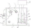
Referring to fig. 1, a sodium ion concentration analyzing and measuring apparatus includes a box 1, a panel 2 is disposed inside the box 1 near a front end, and the apparatus further includes:
a sample vial 5, the sample vial 5 being used to sample the sample water into the laboratory. The upper end of sampling bottle 5 is closed, and the upper end of sampling bottle 5 is provided with and supplies pipeline male sample connection, and the sample connection inner wall is provided with block structure, and block structure is formed by a plurality of fan-shaped rubber pieces concatenation each other.
Specifically, because the sampling bottle 5 adopts a closed structure, the pollution of the external environment to the sample water can be reduced as much as possible in the process of sampling from the site to a laboratory by technicians, and the plugging structure formed by splicing a plurality of fan-shaped rubber sheets is adopted, so that the plugging structure can effectively isolate air and reduce the possibility of sample water pollution in the process of carrying; secondly, when inserting sampling bottle 5 into the device, exert pressure along the sample connection with the pipeline, make fan-shaped sheet rubber deformation demonstrate the opening to make the pipeline can normally put into, and put into the back, fan-shaped sheet rubber pastes the pipeline surface all the time, has certain sealed effect.
It can be understood that, in the sampling process, the sampling bottle 5 needs to be unblocked, so the sampling bottle 5 can be provided with a sealing cover, and the sampling port is arranged on the sealing cover, thereby improving the applicability of the sampling bottle 5.
And the micro peristaltic pump 6 is arranged at the front end of the panel 2, and an inlet of the micro peristaltic pump 6 is connected to the sampling bottle 5 through a pipeline and used for pumping sampling water from the sampling bottle 5.
Specifically, the micro peristaltic pump 6 is adopted to ensure the stability of the flow rate and pressure of the sampling, and provide a stable environment for the subsequent instrument measurement; and the micro peristaltic pump 6 can reduce electromagnetic interference to a certain extent and reduce the fluctuation influence on the product measured by the instrument during working.
In addition, a power switch for controlling the micro peristaltic pump 6 to be turned on and off is further arranged on the panel 2.
Referring to fig. 2 and 3, the alkalization unit 3 is disposed inside the box 1 and located on the back side of the panel 2, and an inlet of the alkalization unit 3 is connected to the micro peristaltic pump 6 for receiving the sample water pumped by the micro peristaltic pump 6 and alkalizing the sample water;
the alkalization unit 3 comprises a reagent bottle 301, a permeation tube 302 and a pipeline, wherein the volatile alkalization agent is filled in the reagent bottle 301, the permeation tube 302 is placed in the reagent bottle 301 and is located above the liquid level of the volatile alkalization agent, and two ends of the permeation tube 302 are respectively connected to the micro peristaltic pump 6 and the measurement unit 4 through the pipeline.
Specifically, the permeation tube 302 is placed in the reagent bottle 301 so as not to contact with the volatile alkalizing agent, while the volatile alkalizing agent can pass through the permeation tube 302 and dissolve in the sample water, wherein OH is contained in the sample water—Will neutralize H in the sample water+Therefore, the accuracy of sodium ion measurement can be improved, and meanwhile, as the permeation tube 302 is not in contact with the volatile alkalization agent, other ions in the volatile alkalization agent are not dissolved in sample water, so that the influence of partial ions on sodium ion measurement can be avoided.
Further, referring to fig. 4, a plurality of pores are disposed on the surface of the permeation tube 302, the inner wall and the outer surface of the permeation tube 302 are covered with a permeation film 303, the permeation film 303 is an expanded polytetrafluoroethylene microporous waterproof permeation film, and the gas can pass through the permeation film 303 but the liquid cannot pass through the permeation film 303 due to the characteristics of the permeation film 303, so that when sample water passes through the permeation tube 302, the gas volatilized by the volatile alkalizer can pass through the permeation film 303 and enter the permeation tube 302, thereby achieving the purpose that the gas automatically enters the permeation tube 302.
It should be noted that the volatile alkalizer has strong volatility, and the specific selection can be selected according to the actual experimental process, which is not described herein again, and the volatilized gas is dissolved in the sample water, wherein OH is in the sample water—Then H can be neutralized+Thereby achieving removal of H+The purpose of the influence.
The measuring unit 4 is arranged at the front end of the panel 2 of the box body 1, and an inlet of the measuring unit 4 is connected to the alkalization unit 3 and used for receiving the sample water alkalized by the alkalization unit 3 and detecting the sample water;
the measuring unit 4 comprises a measuring cell 401, a temperature measuring electrode 402, a sodium measuring electrode 403, a sodium reference electrode 404 and a desk type sodium meter 405, wherein the temperature measuring electrode 402, the sodium measuring electrode 403 and the sodium reference electrode 404 are all connected to the desk type sodium meter 405 through leads, a circulation groove is arranged inside the measuring cell 401, the temperature measuring electrode 402, the sodium measuring electrode 403 and the sodium reference electrode 404 are sequentially inserted into the circulation groove along the flowing direction of sample water, and a water outlet communicated with the circulation groove is further arranged below the measuring cell 401.
Specifically, a temperature measuring electrode 402, a sodium measuring electrode 403 and a sodium reference electrode 404 are sequentially arranged according to the flowing direction of the sample water, so that the sodium reference electrode 404 is placed at the downstream of the sodium measuring electrode 403, and K leaking from the sodium reference electrode 404 is enabled+The sodium ions are directly taken away by the sample water without passing through the sodium measuring electrode 403, so that the interference of measurement is reduced, and the accuracy of sodium ion measurement is further improved.
Referring to fig. 1 and 2, a buffer tube 7 is disposed between the alkalization unit 3 and the measurement unit 4, the buffer tube 7 is formed by winding a corrosion-resistant hose, and the buffer tube 7 is disposed to increase the mixing time of the gas and the sample water permeating into the permeation tube 302 so as to sufficiently neutralize H+Increased H+And (5) removing the effect.
Referring to fig. 2, the permeation tube 302 is in a spiral tube shape, and the axial line thereof is in a spiral line shape, which increases the contact area between the permeation tube 302 and the volatile gas, thereby increasing the gas permeation efficiency.
Specifically, a sealing cover is disposed at an opening of the reagent bottle 301 to prevent the volatile alkalizer from volatilizing.
The working principle of the invention is as follows: during the measurement process, a worker samples the sample water from the field into a laboratory through the sampling bottle 5, then inserts the inlet pipeline on the alkalization unit 3 into the sampling bottle 5, and then starts the micro peristaltic pump 6 to make the sample water sequentially pass through the alkalization unit 3, the buffer tube 7 and the measurement unit 4, when the sample water passes through the permeation tube 302, the volatile alkalization agent volatile gas in the reagent bottle 301 can permeate into the permeation tube 302 and dissolve in the sample water in the permeation tube 302, wherein OH in the sample water—Will neutralize H in the sample water+Thereby shielding off H+For Na+The influence of measurement improves the accuracy of sodium ion measurement.
Example 2
This embodiment differs from embodiment 1 only in the permeation tube 302.
The permeation tube 302 is a coiled tube, the shape of the axial lead of the permeation tube 302 is an involute, and the coiled permeation tube 302 can increase the contact area with the volatile gas, so that the purpose of improving the permeation efficiency is achieved.
Example 3
The embodiment is further improved on the basis of embodiment 1, and in the embodiment:
referring to fig. 5, the reagent bottle 301 includes a bottle body 3011, the bottom of the inner wall of the bottle body 3011 is open, a sealing plate 3012 is disposed at the opening below the bottle body 3011, a lifting mechanism 3013 is disposed at the top of the sealing plate 3012, a piston holder 3014 is disposed at the top of the lifting mechanism 3013, the edge of the piston holder 3014 is tightly attached to the inner wall of the bottle body 3011, an air pressure sensor 3015 is further disposed on the reagent bottle 301, and a probe of the air pressure sensor 3015 extends into the bottle body 3011 for detecting the air pressure inside the bottle body 3011. And the air pressure sensor 3015 and the jacking mechanism 3013 are connected to an external controller.
Further, the jacking mechanism 3013 may be a micro electric push rod or other telescopic rod capable of adjusting height, and will not be described herein again.
In this embodiment, in the measurement process, when the amount of the volatilized gas is reduced, the air pressure sensor 3015 detects that the air pressure is reduced, and the external controller is configured to drive the jacking mechanism 3013 according to the air pressure value fed back by the air pressure sensor 3015, so that the jacking mechanism drives the piston holder 3014 to ascend, and is configured to adjust the air pressure inside the bottle 3011, so that the pressure inside the bottle 3011 maintains a better threshold, and thus the volatilized gas can normally enter the permeation tube 302.
The foregoing is only a preferred embodiment of the present invention, and it should be noted that those skilled in the art can make various improvements and modifications without departing from the principle of the present invention, and these improvements and modifications should also be construed as the protection scope of the present invention. Structures, devices, and methods of operation not specifically described or illustrated herein are generally practiced in the art without specific recitation or limitation.