CN113684787B - Double-row cylindrical open breakwater and using method thereof - Google Patents
Double-row cylindrical open breakwater and using method thereof Download PDFInfo
- Publication number
- CN113684787B CN113684787B CN202111038930.2A CN202111038930A CN113684787B CN 113684787 B CN113684787 B CN 113684787B CN 202111038930 A CN202111038930 A CN 202111038930A CN 113684787 B CN113684787 B CN 113684787B
- Authority
- CN
- China
- Prior art keywords
- rod
- shaped
- hinged
- arc
- fixing plate
- Prior art date
- Legal status (The legal status is an assumption and is not a legal conclusion. Google has not performed a legal analysis and makes no representation as to the accuracy of the status listed.)
- Expired - Fee Related
Links
Images




Classifications
-
- E—FIXED CONSTRUCTIONS
- E02—HYDRAULIC ENGINEERING; FOUNDATIONS; SOIL SHIFTING
- E02B—HYDRAULIC ENGINEERING
- E02B3/00—Engineering works in connection with control or use of streams, rivers, coasts, or other marine sites; Sealings or joints for engineering works in general
- E02B3/04—Structures or apparatus for, or methods of, protecting banks, coasts, or harbours
- E02B3/06—Moles; Piers; Quays; Quay walls; Groynes; Breakwaters ; Wave dissipating walls; Quay equipment
- E02B3/066—Quays
-
- E—FIXED CONSTRUCTIONS
- E02—HYDRAULIC ENGINEERING; FOUNDATIONS; SOIL SHIFTING
- E02B—HYDRAULIC ENGINEERING
- E02B3/00—Engineering works in connection with control or use of streams, rivers, coasts, or other marine sites; Sealings or joints for engineering works in general
- E02B3/04—Structures or apparatus for, or methods of, protecting banks, coasts, or harbours
- E02B3/041—Structures or apparatus for, or methods of, protecting banks, coasts, or harbours using active mechanical means, e.g. fluidizing or pumping
-
- Y—GENERAL TAGGING OF NEW TECHNOLOGICAL DEVELOPMENTS; GENERAL TAGGING OF CROSS-SECTIONAL TECHNOLOGIES SPANNING OVER SEVERAL SECTIONS OF THE IPC; TECHNICAL SUBJECTS COVERED BY FORMER USPC CROSS-REFERENCE ART COLLECTIONS [XRACs] AND DIGESTS
- Y02—TECHNOLOGIES OR APPLICATIONS FOR MITIGATION OR ADAPTATION AGAINST CLIMATE CHANGE
- Y02A—TECHNOLOGIES FOR ADAPTATION TO CLIMATE CHANGE
- Y02A10/00—TECHNOLOGIES FOR ADAPTATION TO CLIMATE CHANGE at coastal zones; at river basins
- Y02A10/11—Hard structures, e.g. dams, dykes or breakwaters
-
- Y—GENERAL TAGGING OF NEW TECHNOLOGICAL DEVELOPMENTS; GENERAL TAGGING OF CROSS-SECTIONAL TECHNOLOGIES SPANNING OVER SEVERAL SECTIONS OF THE IPC; TECHNICAL SUBJECTS COVERED BY FORMER USPC CROSS-REFERENCE ART COLLECTIONS [XRACs] AND DIGESTS
- Y02—TECHNOLOGIES OR APPLICATIONS FOR MITIGATION OR ADAPTATION AGAINST CLIMATE CHANGE
- Y02E—REDUCTION OF GREENHOUSE GAS [GHG] EMISSIONS, RELATED TO ENERGY GENERATION, TRANSMISSION OR DISTRIBUTION
- Y02E10/00—Energy generation through renewable energy sources
- Y02E10/30—Energy from the sea, e.g. using wave energy or salinity gradient
Landscapes
- Engineering & Computer Science (AREA)
- General Engineering & Computer Science (AREA)
- Environmental & Geological Engineering (AREA)
- Ocean & Marine Engineering (AREA)
- Mechanical Engineering (AREA)
- Civil Engineering (AREA)
- Structural Engineering (AREA)
- Revetment (AREA)
Abstract
本发明公开了一种双排圆筒透空式防波堤及其使用方法,属于防波提技术领域,包括V型固定板,所述V型固定板内壁的顶部安装有侧固定板,所述侧固定板的内侧与所述侧固定板外侧之间设有发电滚筒组件,所述V型固定板的顶部靠近所述V型固定板锥型部处安装有侧支撑柱,通过第一发条进行缓冲海浪的功能,通过挡浪弹性布的反作用力可以将海浪在反推回去,同时在挡浪弹性布的松或紧的过程可以带动第一铰接杆运动,通过第一铰接杆进一步带动钢丝绳进行松或紧来带动发电机进行发电。
The invention discloses a double-row cylindrical permeable breakwater and a method for using the same, belonging to the technical field of breakwater, comprising a V-shaped fixing plate, a side fixing plate is installed on the top of the inner wall of the V-shaped fixing plate, and the side fixing plate is installed on the top of the inner wall of the V-shaped fixing plate. A generator drum assembly is arranged between the inner side of the fixing plate and the outer side of the side fixing plate, and a side support column is installed on the top of the V-shaped fixing plate near the conical part of the V-shaped fixing plate, which is carried out by the first spring. The function of buffering the waves, the waves can be pushed back through the reaction force of the wave-blocking elastic cloth, and at the same time, the first hinge rod can be driven to move during the loosening or tightening process of the wave-blocking elastic cloth, and the wire rope can be further driven by the first hinge rod. Loose or tight to drive the generator to generate electricity.
Description
技术领域technical field
本发明涉及一种防波堤,特别是涉及一种双排圆筒透空式防波堤,本发明还涉及一种防波堤使用方法,特别涉及一种双排圆筒透空式防波堤使用方法,属于防波堤技术领域。The present invention relates to a breakwater, in particular to a double-row cylindrical air-permeable breakwater. The invention also relates to a method for using a breakwater, in particular to a method for using a double-row cylindrical air-permeable breakwater, which belongs to the technical field of breakwaters .
背景技术Background technique
防波堤为阻断波浪的冲击力、围护港池、维持水面平稳以保护港口免受坏天气影响、以便船舶安全停泊和作业而修建的水中建筑物。Breakwaters are water structures built to block the impact of waves, protect the harbor basin, maintain a stable water surface to protect the port from bad weather, and allow ships to berth and operate safely.
防波堤还可起到防止港池淤积和波浪冲蚀岸线的作用,它是人工掩护的沿海港口的重要组成部分,一般规定港内的容许波高在0.5~1.0米之间,具体按水域的不同部位、船舶的不同类型与吨位的需要确定,防波堤常由一、二道与岸连接的突堤或不连接的岛堤组成,或由突堤和岛堤共同组成,防波堤掩护的水域常有一个或几个口门供船只进出。The breakwater can also prevent the siltation of the harbor basin and the erosion of the shoreline by waves. It is an important part of the artificially sheltered coastal port. Generally, the allowable wave height in the port is between 0.5 and 1.0 meters, depending on the different parts of the water area. 1. The different types of ships and the tonnage needs to be determined. Breakwaters are often composed of one or two jetties connected to the shore or unconnected island dikes, or composed of jetties and island dikes. The waters covered by breakwaters often have one or several A door for ships to enter and exit.
现有技术中的防波堤在进行防波的时候其采用的方式往往是铺设阻挡结构来实现,或者采用铺设倾斜的岩石的方式进行阻挡,另外现有的也有一些采用阻挡板的方式,但是仅仅只是简单的挡板来进行阻挡,其功能简单而且效果也并不佳,另外针对拍击的波浪产生的力以及波浪波动的浮力产生的能量也无法进行充分的利用,为此设计一种双排圆筒透空式防波堤及其使用方法来优化上述问题。The breakwaters in the prior art are often implemented by laying blocking structures when performing wave protection, or by laying inclined rocks for blocking. In addition, there are also some existing methods of using blocking plates, but only A simple baffle is used to block, its function is simple and the effect is not good. In addition, the force generated by the slapping waves and the energy generated by the buoyancy of the wave fluctuations cannot be fully utilized. For this purpose, a double-row circle is designed. To optimize the above-mentioned problems, the barrel-permeable breakwater and its application method are proposed.
发明内容Contents of the invention
本发明的主要目的是为了提供一种双排圆筒透空式防波堤及其使用方法,通过将固定锥插入至倾斜结构的挡波提的外侧上,然后将V型固定板固定在挡波提的外侧上,通过在挡波提的底部开设有与通口连通的进水口,然后将其浮块插入至通口内,使其水升降可带动浮块升降,通过浮块带动顶连接块升降,通过顶连接块带动底铰接杆运动,通过底铰接杆带动第二铰接杆运动,通过第二铰接杆的运动带动弧形内筒运动,通过弧形内筒压缩弧形限位弹簧进而带动第一铰接杆转动,通过第一铰接杆带动钢丝绳的松或紧,进而使其带动第二发条的松或紧,通过第二发条带动工型捆绳盘转动,进而通过工型捆绳盘带动发电滚筒转动,通过工型捆绳盘的转动进而使其发电机进行发电,当水位较高的时候水浪会拍击防浪堤的低处与外弧形挡浪板撞击接触,通过撞击外弧形挡浪板带动压缩铰接支撑杆,通过铰接支撑杆压缩滑筒运动,通过滑筒带动缓冲弹簧压缩,通过缓冲弹簧的反作用力起到缓冲的功能,通过压缩缓冲弹簧也进一步推动内弧形挡浪板运动,通过内弧形挡浪板推动推动滑条,进而通过推动滑条带动底铰接杆运动,从而也可以带动钢丝绳进行松或紧来进行发电,较高的海浪会撞击到挡浪弹性布上,再配合第一滚筒和第二滚筒滚动使其带动第一发条运动,通过第一发条进行缓冲海浪的功能,通过挡浪弹性布的反作用力可以将海浪在反推回去,同时在挡浪弹性布的松或紧的过程可以带动第一铰接杆运动,通过第一铰接杆进一步带动钢丝绳进行松或紧来带动发电机进行发电。The main purpose of the present invention is to provide a double-row cylindrical air-permeable breakwater and its use method, by inserting the fixing cone into the outer side of the wave-stop lift of the inclined structure, and then fixing the V-shaped fixing plate on the wave-stop lift On the outer side of the baffle, a water inlet connected to the port is opened at the bottom of the baffle, and then the floating block is inserted into the port to make the water rise and fall to drive the floating block up and down, and the floating block drives the top connecting block to rise and fall. The bottom hinge rod is driven to move through the top connecting block, the second hinge rod is driven to move through the bottom hinge rod, the arc-shaped inner cylinder is driven by the movement of the second hinge rod, and the arc-shaped limit spring is compressed by the arc-shaped inner cylinder to drive the first hinge rod. The articulated rod rotates, and the first articulated rod drives the loosening or tightening of the steel wire rope, which in turn drives the second mainspring to loosen or tighten. The power generation drum rotates, and the generator generates power through the rotation of the I-shaped rope tying disc. When the water level is high, the water waves will hit the lower part of the breakwater and collide with the outer arc wave baffle. The shaped wave breaker drives the compressed hinged support rod, compresses the slide cylinder through the hinged support rod, drives the buffer spring to compress through the slide cylinder, plays a buffering function through the reaction force of the buffer spring, and further pushes the inner arc wave breaker through the compressed buffer spring Movement, pushes the slider through the inner arc wave breaker, and then drives the bottom hinge rod to move by pushing the slider, which can also drive the wire rope to loosen or tighten to generate power. Higher waves will hit the wave-stopping elastic cloth, Cooperate with the first roller and the second roller to make it drive the movement of the first clockwork, the function of buffering the waves through the first clockwork, and the reaction force of the wave-blocking elastic cloth can push the waves back, and at the same time block the waves The process of loosening or tightening the elastic cloth can drive the first hinged rod to move, and the first hinged rod further drives the wire rope to loosen or tighten to drive the generator to generate electricity.
本发明的目的可以通过采用如下技术方案达到:The purpose of the present invention can be achieved by adopting the following technical solutions:
一种双排圆筒透空式防波堤,包括V型固定板,所述V型固定板内壁的顶部安装有侧固定板,所述侧固定板的内侧与所述侧固定板外侧之间设有发电滚筒组件,所述V型固定板的顶部靠近所述V型固定板锥型部处安装有侧支撑柱,所述侧支撑柱的顶部通过轴承安装有支撑转杆,所述支撑转杆的外侧靠近所述侧支撑柱处安装有侧固定盘,所述侧固定盘的内侧设有V型铰接杆组件,所述V型铰接杆组件之间设有弧形缓冲架组件,所述V型铰接杆组件的外侧与所述发电滚筒组件之间设有弹性连接组件,所述V型固定板的底部靠近所述侧支撑柱处开设有通口,且所述通口内设有方型浮筒组件,所述方型浮筒组件与所述V型铰接杆组件之间设有铰接推杆组件,所述铰接推杆组件的端部安装有内弧形挡浪板,且所述内弧形挡浪板远离所述侧固定板的一端铰接有缓冲铰接架组件,所述缓冲铰接架组件远离所述内弧形挡浪板的一端铰接有外弧形挡浪板,所述V型铰接杆组件的内侧铰接有挡水滚筒组件。A double-row cylindrical air-permeable breakwater, comprising a V-shaped fixed plate, a side fixed plate is installed on the top of the inner wall of the V-shaped fixed plate, and a The power generation drum assembly, the top of the V-shaped fixed plate is installed with a side support column near the tapered part of the V-shaped fixed plate, and the top of the side support column is installed with a supporting rotating rod through a bearing. A side fixed plate is installed on the outside close to the side support column, and a V-shaped hinged rod assembly is arranged on the inside of the side fixed plate, and an arc-shaped buffer frame assembly is arranged between the V-shaped hinged rod assemblies, and the V-shaped hinged rod assembly is arranged. An elastic connection assembly is provided between the outside of the hinged rod assembly and the power generating drum assembly, and a port is opened at the bottom of the V-shaped fixed plate near the side support column, and a square buoy is arranged in the port Assemblies, a hinged push rod assembly is provided between the square buoy assembly and the V-shaped articulated rod assembly, and an inner arc wave baffle is installed at the end of the hinged push rod assembly, and the inner arc wave baffle One end away from the side fixing plate is hinged with a buffer hinged frame assembly, the end of the buffered hinged frame assembly away from the inner arc wave breaker is hinged with an outer arc wave breaker, and the inner side of the V-shaped hinged rod assembly is hinged with Water retaining roller assembly.
优选的,所述发电滚筒组件包括发电滚筒、工型捆绳盘和发电机,所述侧固定板的一侧中部安装有发电机,所述发电机的输出端贯穿所述侧固定板安装有发电滚筒,所述发电滚筒外侧的两端安装有工型捆绳盘,且所述工型捆绳盘的外侧与所述V型铰接杆组件之间设有弹性连接组件。Preferably, the power generating drum assembly includes a power generating drum, an I-shaped rope reel and a generator, a generator is installed in the middle of one side of the side fixing plate, and a generator is installed at the output end of the generator through the side fixing plate. The power generation drum, the two ends of the outer side of the power generation drum are equipped with I-shaped rope binding discs, and an elastic connection assembly is provided between the outer side of the I-shaped rope binding disc and the V-shaped hinged rod assembly.
优选的,所述V型铰接杆组件包括第一铰接杆和第二铰接杆,所述侧固定盘的内侧靠近边部处分别铰接有第一铰接杆和第二铰接杆,且所述第一铰接杆和第二铰接杆之间安装有弧形缓冲架组件。Preferably, the V-shaped articulated rod assembly includes a first articulated rod and a second articulated rod, the first articulated rod and the second articulated rod are respectively articulated on the inner side of the side fixed plate close to the edge, and the first articulated rod An arc buffer frame assembly is installed between the hinged rod and the second hinged rod.
优选的,所述弧形缓冲架组件包括弧形外筒、弧形内筒和弧形限位弹簧,所述弧形外筒的一端安装在所述第一铰接杆一侧的中部处,且所述第二铰接杆的一侧中部安装有弧形内筒,且所述弧形内筒插入至所述弧形外筒的内侧,所述弧形外筒的内端部与所述弧形内筒之间安装有弧形限位弹簧。Preferably, the arc-shaped buffer frame assembly includes an arc-shaped outer cylinder, an arc-shaped inner cylinder and an arc-shaped limit spring, one end of the arc-shaped outer cylinder is installed at the middle of one side of the first hinged rod, and An arc-shaped inner cylinder is installed in the middle of one side of the second hinged rod, and the arc-shaped inner cylinder is inserted into the inner side of the arc-shaped outer cylinder, and the inner end of the arc-shaped outer cylinder is connected to the arc-shaped outer cylinder. Arc-shaped limit springs are installed between the inner cylinders.
优选的,所述弹性连接组件包括第二侧转杆、第二发条和钢丝绳,所述第二侧转杆安装在所述第一铰接杆外侧的端部处,且所述第二侧转杆的外侧中部安装有轴承,所述轴承上安装有钢丝绳,所述第二发条套设在所述工型捆绳盘的外侧,且所述钢丝绳远离所述第二侧转杆的一端与所述第二发条的外端连接。Preferably, the elastic connection assembly includes a second side turning rod, a second clockwork spring and a steel wire rope, the second side turning rod is installed at an outer end of the first hinged rod, and the second side turning rod The outer middle part of the rod is equipped with a bearing, and a steel wire rope is installed on the bearing, and the second mainspring is sleeved on the outside of the I-shaped rope binding disc, and the end of the steel wire rope away from the second side turning rod is connected to the The outer end of the second spring is connected.
优选的,所述方型浮筒组件包括浮块、顶连接块和内凹槽,所述浮块安装在所述顶连接块的底部,且所述内凹槽开设在所述顶连接块的顶部处,所述浮块插入至所述V型固定板顶部的通口处,所述内凹槽与所述第二铰接杆之间设有铰接推杆组件。Preferably, the square buoy assembly includes a floating block, a top connecting block and an inner groove, the floating block is installed on the bottom of the top connecting block, and the inner groove is opened on the top of the top connecting block , the floating block is inserted into the opening at the top of the V-shaped fixing plate, and a hinged push rod assembly is provided between the inner groove and the second hinged rod.
优选的,所述铰接推杆组件包括第三侧转杆、底铰接杆和推动滑条,所述内凹槽的内侧设有可在所述内凹槽内侧滑动的推动滑条,所述推动滑条的顶部铰接有底铰接杆,所述第二铰接杆外侧的中部安装有第三侧转杆,所述第三侧转杆的外侧套设有轴承,且该轴承与所述底铰接杆远离所述推动滑条的一端铰接。Preferably, the hinged push rod assembly includes a third side turning lever, a bottom hinged lever and a push slide bar, the inside of the inner groove is provided with a push slide bar that can slide inside the inner groove, and the push The top of the slide bar is hinged with a bottom hinged rod, and the middle part of the outside of the second hinged rod is equipped with a third side turning rod. One end away from the push slider is hinged.
优选的,所述缓冲铰接架组件包括侧铰接座、缓冲弹簧、旋转杆、铰接支撑杆和滑筒,所述内弧形挡浪板外侧的端中部安装有侧铰接座,所述侧铰接座的内侧铰接有旋转杆,所述旋转杆的外端部与所述侧铰接座之间安装有缓冲弹簧,所述缓冲弹簧的另一端安装有滑筒,且所述滑筒套设在所述旋转杆的外侧,所述滑筒的外侧铰接有铰接支撑杆,所述铰接支撑杆远离所述内弧形挡浪板的一端与所述外弧形挡浪板的内中部铰接。Preferably, the buffer hinge frame assembly includes a side hinge seat, a buffer spring, a rotating rod, a hinge support rod and a sliding cylinder, and a side hinge seat is installed at the middle end of the outer side of the inner arc-shaped wave breaker, and the side hinge seat A rotating rod is hinged on the inner side, and a buffer spring is installed between the outer end of the rotating rod and the side hinge seat, and a sliding sleeve is installed on the other end of the buffer spring, and the sliding sleeve is sleeved on the rotating The outer side of the rod, the outer side of the sliding cylinder is hinged with a hinged support rod, and the end of the hinged support rod away from the inner arc wave breaker is hinged with the inner middle of the outer arc wave breaker.
优选的,所述挡水滚筒组件包括挡浪弹性布、第一滚筒、第二滚筒、第一侧转杆、第一发条和外轴承,所述第一铰接杆的内侧端部通过外轴承安装有第一侧转杆,所述第一侧转杆的内端部安装有第一滚筒,所述第二铰接杆内侧的端部通过外轴承安装有另一组第一侧转杆,且所述第一侧转杆的内侧安装有第二滚筒,所述第一滚筒和第二滚筒的外侧连接有挡浪弹性布,所述外轴承的内侧与所述第一侧转杆之间设有第一发条。Preferably, the water-retaining roller assembly includes a wave-retaining elastic cloth, a first roller, a second roller, a first side-rotating rod, a first mainspring and an outer bearing, and the inner end of the first hinged rod passes through the outer bearing A first side turning rod is installed, the inner end of the first side turning rod is equipped with a first roller, and the inner end of the second hinged rod is installed with another set of first side turning rods through an outer bearing, and The inner side of the first side turning rod is installed with a second roller, the outer sides of the first roller and the second roller are connected with wave-resistant elastic cloth, and the inner side of the outer bearing and the first side turning rod are provided. There is a first spring.
优选的,所述V型固定板的外侧等间距设有固定锥,且所述固定锥采用金属材质制备而成,所述V型固定板为网体结构。Preferably, the outside of the V-shaped fixing plate is equidistantly provided with fixing cones, and the fixing cones are made of metal, and the V-shaped fixing plate is a mesh structure.
优选的,所述侧支撑柱焊接在所述V型固定板的顶部处,所述浮块采用橡胶材质制成而成,且所述浮块的内部为中空结构。Preferably, the side support column is welded on the top of the V-shaped fixing plate, the floating block is made of rubber material, and the inside of the floating block is a hollow structure.
一种双排圆筒透空式防波堤使用方法,包括如下步骤:A method for using a double-row cylindrical air-permeable breakwater, comprising the following steps:
步骤1:通过将固定锥插入至倾斜结构的挡波提的外侧上,然后将V型固定板固定在挡波提的外侧上;Step 1: By inserting the fixing cone onto the outside of the wave-stop of the inclined structure, and then fixing the V-shaped fixing plate on the outside of the wave-stop;
步骤2:通过在挡波提的底部开设有与通口连通的进水口,然后将其浮块插入至通口内,使其水升降可带动浮块升降;Step 2: Open a water inlet connected to the port at the bottom of the baffle, and then insert the floating block into the port to make the water rise and fall to drive the floating block up and down;
步骤3:通过浮块带动顶连接块升降,通过顶连接块带动底铰接杆运动,通过底铰接杆带动第二铰接杆运动;Step 3: Drive the top connecting block up and down through the floating block, drive the bottom hinged rod to move through the top connecting block, and drive the second hinged rod to move through the bottom hinged rod;
步骤4:通过第二铰接杆的运动带动弧形内筒运动,通过弧形内筒压缩弧形限位弹簧进而带动第一铰接杆转动;Step 4: Drive the arc-shaped inner cylinder to move through the movement of the second hinge rod, and compress the arc-shaped limit spring through the arc-shaped inner cylinder to drive the first hinge rod to rotate;
步骤5:通过第一铰接杆带动钢丝绳的松或紧,进而使其带动第二发条的松或紧,通过第二发条带动工型捆绳盘转动,进而通过工型捆绳盘带动发电滚筒转动;Step 5: Use the first articulated rod to drive the wire rope to loosen or tighten, and then make it drive the second spring to loosen or tighten, drive the I-shaped rope reel to rotate through the second spring, and then drive the I-shaped rope reel to generate electricity drum rotation;
步骤6:通过工型捆绳盘的转动进而使其发电机进行发电;Step 6: Make the generator generate electricity through the rotation of the I-shaped tying rope reel;
步骤7:当水位较高的时候水浪会拍击防浪堤的低处与外弧形挡浪板撞击接触,通过撞击外弧形挡浪板带动压缩铰接支撑杆,通过铰接支撑杆压缩滑筒运动,通过滑筒带动缓冲弹簧压缩,通过缓冲弹簧的反作用力起到缓冲的功能;Step 7: When the water level is high, the water waves will hit the lower part of the breakwater and collide with the outer arc wave baffle, and the hinged support rod will be compressed by hitting the outer arc wave baffle, and the sliding cylinder will be compressed by the hinged support rod. , the buffer spring is driven by the slider to compress, and the reaction force of the buffer spring plays a buffering function;
步骤8:通过压缩缓冲弹簧也进一步推动内弧形挡浪板运动,通过内弧形挡浪板推动推动滑条,进而通过推动滑条带动底铰接杆运动,从而也可以带动钢丝绳进行松或紧来进行发电;Step 8: Compress the buffer spring to further push the movement of the inner arc wave breaker, push the slider through the inner arc wave breaker, and then drive the bottom hinge rod to move by pushing the slide bar, which can also drive the wire rope to loosen or tighten. power generation;
步骤9:较高的海浪会撞击到挡浪弹性布上,再配合第一滚筒和第二滚筒滚动使其带动第一发条运动,通过第一发条进行缓冲海浪的功能;Step 9: Higher waves will hit the wave-blocking elastic cloth, and then cooperate with the first roller and the second roller to roll to drive the movement of the first mainspring, and the function of buffering the waves through the first mainspring;
步骤10:通过挡浪弹性布的反作用力可以将海浪在反推回去,同时在挡浪弹性布的松或紧的过程可以带动第一铰接杆运动,通过第一铰接杆进一步带动钢丝绳进行松或紧来带动发电机进行发电。Step 10: The wave can be pushed back by the reaction force of the wave-blocking elastic cloth. At the same time, the first hinged rod can be driven to move during the loosening or tightening process of the wave-blocking elastic cloth, and the steel wire rope can be further driven by the first hinged rod to loosen or tighten. Tightly drive the generator to generate electricity.
本发明的有益技术效果:Beneficial technical effect of the present invention:
本发明提供的一种双排圆筒透空式防波堤及其使用方法,通过将固定锥插入至倾斜结构的挡波提的外侧上,然后将V型固定板固定在挡波提的外侧上,通过在挡波提的底部开设有与通口连通的进水口,然后将其浮块插入至通口内,使其水升降可带动浮块升降,通过浮块带动顶连接块升降,通过顶连接块带动底铰接杆运动,通过底铰接杆带动第二铰接杆运动,通过第二铰接杆的运动带动弧形内筒运动,通过弧形内筒压缩弧形限位弹簧进而带动第一铰接杆转动,通过第一铰接杆带动钢丝绳的松或紧,进而使其带动第二发条的松或紧,通过第二发条带动工型捆绳盘转动,进而通过工型捆绳盘带动发电滚筒转动,通过工型捆绳盘的转动进而使其发电机进行发电,当水位较高的时候水浪会拍击防浪堤的低处与外弧形挡浪板撞击接触,通过撞击外弧形挡浪板带动压缩铰接支撑杆,通过铰接支撑杆压缩滑筒运动,通过滑筒带动缓冲弹簧压缩,通过缓冲弹簧的反作用力起到缓冲的功能,通过压缩缓冲弹簧也进一步推动内弧形挡浪板运动,通过内弧形挡浪板推动推动滑条,进而通过推动滑条带动底铰接杆运动,从而也可以带动钢丝绳进行松或紧来进行发电,较高的海浪会撞击到挡浪弹性布上,再配合第一滚筒和第二滚筒滚动使其带动第一发条运动,通过第一发条进行缓冲海浪的功能,通过挡浪弹性布的反作用力可以将海浪在反推回去,同时在挡浪弹性布的松或紧的过程可以带动第一铰接杆运动,通过第一铰接杆进一步带动钢丝绳进行松或紧来带动发电机进行发电。The invention provides a double-row cylindrical air-permeable breakwater and its use method. By inserting the fixing cone into the outer side of the inclined structure of the wave-stopping lift, and then fixing the V-shaped fixing plate on the outside of the wave-stopping lift, By opening a water inlet connected to the port at the bottom of the baffle, and then inserting its floating block into the port, the water can rise and fall to drive the floating block up and down. Drive the bottom hinge rod to move, drive the second hinge rod to move through the bottom hinge rod, drive the arc-shaped inner cylinder to move through the movement of the second hinge rod, compress the arc-shaped limit spring through the arc-shaped inner cylinder to drive the first hinge rod to rotate, The first articulated rod drives the loosening or tightening of the steel wire rope, and then makes it drive the second mainspring to loosen or tighten, and the second mainspring drives the I-shaped rope tying disc to rotate, and then the I-shaped tying rope disc drives the generator drum to rotate, Through the rotation of the I-shaped rope reel, the generator can generate electricity. When the water level is high, the water waves will hit the lower part of the breakwater and collide with the outer arc wave baffle, which is driven by hitting the outer arc wave baffle. Compress the hinged support rod, compress the sliding cylinder through the hinged support rod, drive the buffer spring to compress through the sliding cylinder, and play a buffering function through the reaction force of the buffer spring. The arc-shaped wave breaker pushes the slide bar, and then drives the bottom hinge rod to move by pushing the slide bar, which can also drive the wire rope to loosen or tighten to generate electricity. Higher waves will hit the wave-stop elastic cloth, and then cooperate with the first The roller and the second roller roll to drive the movement of the first mainspring, and the function of buffering the waves is performed by the first mainspring, and the waves can be pushed back by the reaction force of the wave-blocking elastic cloth. The process of tightening or tightening can drive the first articulated rod to move, and the first articulated rod further drives the wire rope to loosen or tighten to drive the generator to generate electricity.
附图说明Description of drawings
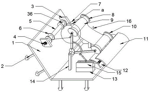
图1为按照本发明的一种双排圆筒透空式防波堤及其使用方法的一优选实施例的装置整体立体结构图;Fig. 1 is an overall three-dimensional structure diagram of the device according to a preferred embodiment of a double-row cylindrical air-permeable breakwater and its use method of the present invention;
图2为按照本发明的一种双排圆筒透空式防波堤及其使用方法的一优选实施例的装置整体立体结构分解图;Fig. 2 is an exploded view of the overall three-dimensional structure of the device according to a preferred embodiment of a double-row cylindrical air-permeable breakwater and its use method of the present invention;
图3为按照本发明的一种双排圆筒透空式防波堤及其使用方法的一优选实施例的内下层阻隔板组件立体结构示意图;Fig. 3 is a three-dimensional structural schematic diagram of the inner and lower barrier plate assembly of a preferred embodiment of a double-row cylindrical air-permeable breakwater and its use method according to the present invention;
图4为按照本发明的一种双排圆筒透空式防波堤及其使用方法的一优选实施例的外滚筒组件以及挡浪弹性布组件组合立体结构示意图;Fig. 4 is a schematic diagram of the combined three-dimensional structure of the outer drum assembly and the wave-blocking elastic cloth assembly of a preferred embodiment of a double-row cylindrical air-permeable breakwater and its use method according to the present invention;
图5为按照本发明的一种双排圆筒透空式防波堤及其使用方法的一优选实施例的支撑架以及V型连接架和弧形缓冲架组件组合立体结构示意图;Fig. 5 is a schematic diagram of a combined three-dimensional structure of a support frame, a V-shaped connecting frame and a curved buffer frame assembly of a preferred embodiment of a double-row cylindrical air-permeable breakwater and its use method according to the present invention;
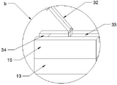
图6为按照本发明的一种双排圆筒透空式防波堤及其使用方法的一优选实施例的b处结构放大图;Figure 6 is an enlarged view of the structure at b of a preferred embodiment of a double-row cylindrical air-permeable breakwater and its use method according to the present invention;
图7为按照本发明的一种双排圆筒透空式防波堤及其使用方法的一优选实施例的支撑架以及V型连接架和弧形缓冲架组件组合侧剖视图;Fig. 7 is a side sectional view of a combination of a support frame, a V-shaped connecting frame and an arc buffer frame assembly according to a preferred embodiment of a double-row cylindrical air-permeable breakwater and its use method of the present invention;
图8为按照本发明的一种双排圆筒透空式防波堤及其使用方法的一优选实施例的内外缓冲挡板组件结构侧剖视图;Fig. 8 is a side cross-sectional view of a structure of inner and outer buffer baffles of a preferred embodiment of a double-row cylindrical air-permeable breakwater and its use method according to the present invention;
图9为按照本发明的一种双排圆筒透空式防波堤及其使用方法的一优选实施例的a处结构放大图。Fig. 9 is an enlarged view of the structure at a of a preferred embodiment of a double-row cylindrical air-permeable breakwater and its use method according to the present invention.
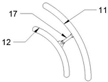
图中:1-V型固定板,2-固定锥,3-侧固定板,4-发电机,5-发电滚筒,6-工型捆绳盘,7-钢丝绳,8-第一滚筒,9-挡浪弹性布,10-第二滚筒,11-外弧形挡浪板,12-内弧形挡浪板,13-浮块,14-侧支撑柱,15-顶连接块,16-支撑转杆,17-铰接支撑杆,18-旋转杆,19-滑筒,20-缓冲弹簧,21-侧铰接座,22-第一侧转杆,23-外轴承,24-第一发条,25-侧固定盘,26-第一铰接杆,27-第二铰接杆,28-弧形外筒,29-弧形内筒,30-第二侧转杆,31-第三侧转杆,32-底铰接杆,33-推动滑条,34-内凹槽,35-弧形限位弹簧,36-第二发条。In the figure: 1-V-shaped fixed plate, 2-fixed cone, 3-side fixed plate, 4-generator, 5-generating drum, 6-I-shaped rope reel, 7-wire rope, 8-first drum, 9 -Blast wave elastic cloth, 10-second roller, 11-outer arc wave breaker, 12-inner arc wave breaker, 13-floating block, 14-side support column, 15-top connecting block, 16-support rotating rod , 17-hinged support rod, 18-rotating rod, 19-slider, 20-buffer spring, 21-side hinged seat, 22-first side rotating rod, 23-outer bearing, 24-first mainspring, 25- Side fixed plate, 26-the first articulated rod, 27-the second articulated rod, 28-curved outer cylinder, 29-curved inner cylinder, 30-the second side rotation rod, 31-the third side rotation rod, 32- Bottom hinge rod, 33-promoting slide bar, 34-inner groove, 35-arc limit spring, 36-second clockwork.
具体实施方式Detailed ways
为使本领域技术人员更加清楚和明确本发明的技术方案,下面结合实施例及附图对本发明作进一步详细的描述,但本发明的实施方式不限于此。In order to make the technical solutions of the present invention clearer and clearer to those skilled in the art, the present invention will be further described in detail below in conjunction with the examples and accompanying drawings, but the embodiments of the present invention are not limited thereto.
如图1-图9所示,本实施例提供的一种双排圆筒透空式防波堤,包括V型固定板1,V型固定板1内壁的顶部安装有侧固定板3,侧固定板3的内侧与侧固定板3外侧之间设有发电滚筒组件,V型固定板1的顶部靠近V型固定板1锥型部处安装有侧支撑柱14,侧支撑柱14的顶部通过轴承安装有支撑转杆16,支撑转杆16的外侧靠近侧支撑柱14处安装有侧固定盘25,侧固定盘25的内侧设有V型铰接杆组件,V型铰接杆组件之间设有弧形缓冲架组件,V型铰接杆组件的外侧与发电滚筒组件之间设有弹性连接组件,V型固定板1的底部靠近侧支撑柱14处开设有通口,且通口内设有方型浮筒组件,方型浮筒组件与V型铰接杆组件之间设有铰接推杆组件,铰接推杆组件的端部安装有内弧形挡浪板12,且内弧形挡浪板12远离侧固定板3的一端铰接有缓冲铰接架组件,缓冲铰接架组件远离内弧形挡浪板12的一端铰接有外弧形挡浪板11,V型铰接杆组件的内侧铰接有挡水滚筒组件。As shown in Figures 1-9, a double-row cylindrical air-permeable breakwater provided in this embodiment includes a V-shaped fixed
总工作原理:通过将固定锥2插入至倾斜结构的挡波提的外侧上,然后将V型固定板1固定在挡波提的外侧上,通过在挡波提的底部开设有与通口连通的进水口,然后将其浮块13插入至通口内,使其水升降可带动浮块13升降,通过浮块13带动顶连接块15升降,通过顶连接块15带动底铰接杆32运动,通过底铰接杆32带动第二铰接杆27运动,通过第二铰接杆27的运动带动弧形内筒29运动,通过弧形内筒29压缩弧形限位弹簧35进而带动第一铰接杆26转动,通过第一铰接杆26带动钢丝绳7的松或紧,进而使其带动第二发条36的松或紧,通过第二发条36带动工型捆绳盘6转动,进而通过工型捆绳盘6带动发电滚筒5转动,通过工型捆绳盘6的转动进而使其发电机4进行发电,当水位较高的时候水浪会拍击防浪堤的低处与外弧形挡浪板11撞击接触,通过撞击外弧形挡浪板11带动压缩铰接支撑杆17,通过铰接支撑杆17压缩滑筒19运动,通过滑筒19带动缓冲弹簧20压缩,通过缓冲弹簧20的反作用力起到缓冲的功能,通过压缩缓冲弹簧20也进一步推动内弧形挡浪板12运动,通过内弧形挡浪板12推动推动滑条33,进而通过推动滑条33带动底铰接杆32运动,从而也可以带动钢丝绳7进行松或紧来进行发电,较高的海浪会撞击到挡浪弹性布9上,再配合第一滚筒8和第二滚筒10滚动使其带动第一发条24运动,通过第一发条24进行缓冲海浪的功能,通过挡浪弹性布9的反作用力可以将海浪在反推回去,同时在挡浪弹性布9的松或紧的过程可以带动第一铰接杆26运动,通过第一铰接杆26进一步带动钢丝绳7进行松或紧来带动发电机4进行发电。General working principle: by inserting the fixing
在本实施例中,发电滚筒组件包括发电滚筒5、工型捆绳盘6和发电机4,侧固定板3的一侧中部安装有发电机4,发电机4的输出端贯穿侧固定板3安装有发电滚筒5,发电滚筒5外侧的两端安装有工型捆绳盘6,且工型捆绳盘6的外侧与V型铰接杆组件之间设有弹性连接组件,弹性连接组件包括第二侧转杆30、第二发条36和钢丝绳7,第二侧转杆30安装在第一铰接杆26外侧的端部处,且第二侧转杆30的外侧中部安装有轴承,轴承上安装有钢丝绳7,第二发条36套设在工型捆绳盘6的外侧,且钢丝绳7远离第二侧转杆30的一端与第二发条36的外端连接。In this embodiment, the generator drum assembly includes a
局部工作原理:通过钢丝绳7的松或紧,进而使其带动第二发条36的松或紧,通过第二发条36带动工型捆绳盘6转动,进而通过工型捆绳盘6带动发电滚筒5转动,通过工型捆绳盘6的转动进而使其发电机4进行发电。Partial working principle: through the loosening or tightening of the
在本实施例中,V型铰接杆组件包括第一铰接杆26和第二铰接杆27,侧固定盘25的内侧靠近边部处分别铰接有第一铰接杆26和第二铰接杆27,且第一铰接杆26和第二铰接杆27之间安装有弧形缓冲架组件,弧形缓冲架组件包括弧形外筒28、弧形内筒29和弧形限位弹簧35,弧形外筒28的一端安装在第一铰接杆26一侧的中部处,且第二铰接杆27的一侧中部安装有弧形内筒29,且弧形内筒29插入至弧形外筒28的内侧,弧形外筒28的内端部与弧形内筒29之间安装有弧形限位弹簧35。In this embodiment, the V-shaped articulated rod assembly includes a first articulated
局部工作原理:通过第一铰接杆26和第二铰接杆27角度的改变并配合弧形外筒28、弧形内筒29和弧形限位弹簧35实现限位调节角度的功能。Partial working principle: through the change of the angle of the first articulated
在本实施例中,方型浮筒组件包括浮块13、顶连接块15和内凹槽34,浮块13安装在顶连接块15的底部,且内凹槽34开设在顶连接块15的顶部处,浮块13插入至V型固定板1顶部的通口处,内凹槽34与第二铰接杆27之间设有铰接推杆组件,铰接推杆组件包括第三侧转杆31、底铰接杆32和推动滑条33,内凹槽34的内侧设有可在内凹槽34内侧滑动的推动滑条33,推动滑条33的顶部铰接有底铰接杆32,第二铰接杆27外侧的中部安装有第三侧转杆31,第三侧转杆31的外侧套设有轴承,且该轴承与底铰接杆32远离推动滑条33的一端铰接。In this embodiment, the square buoy assembly includes a floating
局部工作原理:通过在挡波提的底部开设有与通口连通的进水口,然后将其浮块13插入至通口内,使其水升降可带动浮块13升降,通过浮块13带动顶连接块15升降,通过顶连接块15带动底铰接杆32运动,通过底铰接杆32带动第二铰接杆27运动。Partial working principle: by opening a water inlet connected to the port at the bottom of the baffle, and then inserting the floating
在本实施例中,缓冲铰接架组件包括侧铰接座21、缓冲弹簧20、旋转杆18、铰接支撑杆17和滑筒19,内弧形挡浪板12外侧的端中部安装有侧铰接座21,侧铰接座21的内侧铰接有旋转杆18,旋转杆18的外端部与侧铰接座21之间安装有缓冲弹簧20,缓冲弹簧20的另一端安装有滑筒19,且滑筒19套设在旋转杆18的外侧,滑筒19的外侧铰接有铰接支撑杆17,铰接支撑杆17远离内弧形挡浪板12的一端与外弧形挡浪板11的内中部铰接。In this embodiment, the buffer hinged frame assembly includes a side hinged
局部工作原理:通过撞击外弧形挡浪板11带动压缩铰接支撑杆17,通过铰接支撑杆17压缩滑筒19运动,通过滑筒19带动缓冲弹簧20压缩,通过缓冲弹簧20的反作用力起到缓冲的功能,通过压缩缓冲弹簧20也进一步推动内弧形挡浪板12运动。Partial working principle: the compression of the hinged
在本实施例中,挡水滚筒组件包括挡浪弹性布9、第一滚筒8、第二滚筒10、第一侧转杆22、第一发条24和外轴承23,第一铰接杆26的内侧端部通过外轴承23安装有第一侧转杆22,第一侧转杆22的内端部安装有第一滚筒8,第二铰接杆27内侧的端部通过外轴承23安装有另一组第一侧转杆22,且第一侧转杆22的内侧安装有第二滚筒10,第一滚筒8和第二滚筒10的外侧连接有挡浪弹性布9,外轴承23的内侧与第一侧转杆22之间设有第一发条24。In this embodiment, the water-retaining roller assembly includes the wave-retaining
局部工作原理:较高的海浪会撞击到挡浪弹性布9上,再配合第一滚筒8和第二滚筒10滚动使其带动第一发条24运动,通过第一发条24进行缓冲海浪的功能,通过挡浪弹性布9的反作用力可以将海浪在反推回去。Partial working principle: Higher waves will hit the wave-blocking
在本实施例中,V型固定板1的外侧等间距设有固定锥2,且固定锥2采用金属材质制备而成,V型固定板1为网体结构。In this embodiment, the outside of the V-shaped
在本实施例中,侧支撑柱14焊接在V型固定板1的顶部处,浮块13采用橡胶材质制成而成,且浮块13的内部为中空结构。In this embodiment, the
一种双排圆筒透空式防波堤使用方法,包括如下步骤:A method for using a double-row cylindrical air-permeable breakwater, comprising the following steps:
步骤1:通过将固定锥2插入至倾斜结构的挡波提的外侧上,然后将V型固定板1固定在挡波提的外侧上;Step 1: By inserting the fixing
步骤2:通过在挡波提的底部开设有与通口连通的进水口,然后将其浮块13插入至通口内,使其水升降可带动浮块13升降;Step 2: Open a water inlet connected to the port at the bottom of the baffle, and then insert the floating
步骤3:通过浮块13带动顶连接块15升降,通过顶连接块15带动底铰接杆32运动,通过底铰接杆32带动第二铰接杆27运动;Step 3: drive the
步骤4:通过第二铰接杆27的运动带动弧形内筒29运动,通过弧形内筒29压缩弧形限位弹簧35进而带动第一铰接杆26转动;Step 4: The movement of the second articulated
步骤5:通过第一铰接杆26带动钢丝绳7的松或紧,进而使其带动第二发条36的松或紧,通过第二发条36带动工型捆绳盘6转动,进而通过工型捆绳盘6带动发电滚筒5转动;Step 5: Drive the
步骤6:通过工型捆绳盘6的转动进而使其发电机4进行发电;Step 6: Make the
步骤7:当水位较高的时候水浪会拍击防浪堤的低处与外弧形挡浪板11撞击接触,通过撞击外弧形挡浪板11带动压缩铰接支撑杆17,通过铰接支撑杆17压缩滑筒19运动,通过滑筒19带动缓冲弹簧20压缩,通过缓冲弹簧20的反作用力起到缓冲的功能;Step 7: When the water level is high, the water waves will hit the lower part of the breakwater and come into contact with the outer
步骤8:通过压缩缓冲弹簧20也进一步推动内弧形挡浪板12运动,通过内弧形挡浪板12推动推动滑条33,进而通过推动滑条33带动底铰接杆32运动,从而也可以带动钢丝绳7进行松或紧来进行发电;Step 8: Compress the
步骤9:较高的海浪会撞击到挡浪弹性布9上,再配合第一滚筒8和第二滚筒10滚动使其带动第一发条24运动,通过第一发条24进行缓冲海浪的功能;Step 9: Higher waves will hit the wave-blocking
步骤10:通过挡浪弹性布9的反作用力可以将海浪在反推回去,同时在挡浪弹性布9的松或紧的过程可以带动第一铰接杆26运动,通过第一铰接杆26进一步带动钢丝绳7进行松或紧来带动发电机4进行发电。Step 10: The waves can be pushed back by the reaction force of the wave-blocking
以上,仅为本发明进一步的实施例,但本发明的保护范围并不局限于此,任何熟悉本技术领域的技术人员在本发明所公开的范围内,根据本发明的技术方案及其构思加以等同替换或改变,都属于本发明的保护范围。The above are only further embodiments of the present invention, but the scope of protection of the present invention is not limited thereto. Any person familiar with the technical field shall, within the scope disclosed by the present invention, make further improvements according to the technical scheme of the present invention and its design. Equivalent replacements or changes all belong to the protection scope of the present invention.
Claims (10)
Priority Applications (1)
| Application Number | Priority Date | Filing Date | Title |
|---|---|---|---|
| CN202111038930.2A CN113684787B (en) | 2021-09-06 | 2021-09-06 | Double-row cylindrical open breakwater and using method thereof |
Applications Claiming Priority (1)
| Application Number | Priority Date | Filing Date | Title |
|---|---|---|---|
| CN202111038930.2A CN113684787B (en) | 2021-09-06 | 2021-09-06 | Double-row cylindrical open breakwater and using method thereof |
Publications (2)
| Publication Number | Publication Date |
|---|---|
| CN113684787A CN113684787A (en) | 2021-11-23 |
| CN113684787B true CN113684787B (en) | 2022-11-08 |
Family
ID=78585346
Family Applications (1)
| Application Number | Title | Priority Date | Filing Date |
|---|---|---|---|
| CN202111038930.2A Expired - Fee Related CN113684787B (en) | 2021-09-06 | 2021-09-06 | Double-row cylindrical open breakwater and using method thereof |
Country Status (1)
| Country | Link |
|---|---|
| CN (1) | CN113684787B (en) |
Families Citing this family (2)
| Publication number | Priority date | Publication date | Assignee | Title |
|---|---|---|---|---|
| CN116279991B (en) * | 2023-03-16 | 2025-09-09 | 青岛智能导航与控制研究所 | Cable release device |
| CN119221422B (en) * | 2024-12-05 | 2025-03-21 | 福州市规划设计研究院集团有限公司 | An ecological hole-retaining natural revetment |
Family Cites Families (4)
| Publication number | Priority date | Publication date | Assignee | Title |
|---|---|---|---|---|
| CN103835274A (en) * | 2014-03-24 | 2014-06-04 | 长沙理工大学 | Wave power generation device combined with floating seawall and port trestle |
| IL267357B2 (en) * | 2019-06-11 | 2024-05-01 | Elta Systems Ltd | Floating breakwater structure |
| CN111648909B (en) * | 2020-04-24 | 2021-11-30 | 河海大学 | Double-cylinder floating breakwater auxiliary power generation device |
| CN112095543B (en) * | 2020-08-08 | 2021-11-09 | 浙江水利水电学院 | Edge bank wave retaining structure and construction method thereof |
-
2021
- 2021-09-06 CN CN202111038930.2A patent/CN113684787B/en not_active Expired - Fee Related
Also Published As
| Publication number | Publication date |
|---|---|
| CN113684787A (en) | 2021-11-23 |
Similar Documents
| Publication | Publication Date | Title |
|---|---|---|
| US10094356B2 (en) | Multi mode wave energy converter with elongated wave front parallel float having integral lower shoaling extension | |
| US20130113211A1 (en) | Submergable sloped absorption barrier wave energy converter | |
| CN117465621B (en) | Floating platform structure suitable for offshore floating type photovoltaic system | |
| CN113684787A (en) | Double-row cylinder open type wave-proof mention and use method thereof | |
| CN212138778U (en) | Chain type anti-wave ocean ecological floating restoration device | |
| CN106049351B (en) | Vertical breakwater with saturating stream berthing function | |
| CN113718708A (en) | Offshore photovoltaic porous multi-stage attenuation wave energy floating breakwater and installation method thereof | |
| CN107792298B (en) | An automatic retractable chain device for floating water photovoltaic mooring | |
| CN107858997A (en) | A kind of floating breakwater for having wave-energy power generation and sea drift garbage reclamation function concurrently | |
| CN118148193A (en) | Self-maintenance anti-scouring device for offshore wind power pile foundation and application method thereof | |
| CA2847346A1 (en) | Submergible sloped absorption barrier wave energy converter | |
| CN113445469B (en) | A floating box-type breakwater structure with a double-tube floating power generation device | |
| CN119021144B (en) | Floating multi-stage wave reduction device | |
| CN205822127U (en) | There is the vertical breakwater of stream alongside function | |
| CN114541319B (en) | A kind of HDPE water semi-submersible breakwater and its operation method | |
| CN110107454A (en) | Floating type Oversea wind power generation and Wave power generation equipment and control method | |
| CN116575404B (en) | Pile foundation scour protection device for offshore wind power installation | |
| CN215052650U (en) | Green reinforced (rfd) beach protective structure of planting | |
| JPH0419362A (en) | Wave power energy converter | |
| CN216445899U (en) | Dykes and dams for hydraulic engineering | |
| CN213867618U (en) | Protecting against shock water conservancy dykes and dams | |
| CN111576351B (en) | Self-signal adjusting and protecting cofferdam wall in flood disaster flood season | |
| CN116654178A (en) | Marine ecology automatic monitoring buoy device and method | |
| CN223322755U (en) | Wind wave resistant device for deep-open sea cultivation fence | |
| CN219280643U (en) | Quantitative drainage structure for farmland waterlogging prevention |
Legal Events
| Date | Code | Title | Description |
|---|---|---|---|
| PB01 | Publication | ||
| PB01 | Publication | ||
| SE01 | Entry into force of request for substantive examination | ||
| SE01 | Entry into force of request for substantive examination | ||
| GR01 | Patent grant | ||
| GR01 | Patent grant | ||
| CF01 | Termination of patent right due to non-payment of annual fee |
Granted publication date: 20221108 |
|
| CF01 | Termination of patent right due to non-payment of annual fee |