Disclosure of Invention
Aiming at the existing problems, the invention aims to provide a special-shaped box girder erection construction process based on a bow-string type center line positioning method, the process is used for erecting a special-shaped girder by the bow-string type center line positioning method, the problem that the traditional line positioning method is limited by a lot in the erection of the special-shaped girder is effectively solved, and the special-shaped box girder erection construction process has the characteristics of less investment, high precision, safe operation, strong dynamic property and no great influence of local wind and sand.
In order to achieve the purpose, the technical scheme adopted by the invention is as follows:
a construction process for erecting a special-shaped box girder based on an arch chord type center line positioning method comprises the following steps
S1, constructing a rail extension pile foundation and establishing a stable slide rail foundation;
s2, after the construction of the slide rail foundation is finished, prefabricating a special-shaped track beam and installing a rail bearing beam embedded part;
s3, erecting the special-shaped box girder by adopting a method based on bow-string type center line positioning, and assembling the special-shaped box girder and the slide rail foundation
S301, manufacturing an arch string type center line positioning tool;
s302, positioning is carried out by using a bow-string type center line positioning tool, and a special-shaped box girder is erected.
Preferably, the slide rail foundation in step S1 includes a reference pile, a control pile, a construction pile and a pile cap, and the slide rail foundation is established by the following steps:
s101, pile foundation point positions are arranged according to design requirements, and after pile position positioning and pile test construction are finished, pile foundation construction is carried out by adopting a long spiral drilling pile-pouring post-dowel construction process;
wherein: in the pile foundation construction process, adopting a long spiral drilling machine to carry out dry hole forming construction, and simultaneously adopting a pile jumping method to carry out construction;
s102, pile foundation construction is completed, pile body integrity and bearing capacity detection is carried out after design strength is achieved, and pile foundation construction can be carried out if the detection is qualified;
s103, after the construction of the main body structure of the upper portion of the pile foundation is completed, the construction of the pile and the beam of the top elevation upper portion of the standard pile cap is carried out, secondary pile splicing is needed, reinforcing steel bars are bound, iron pieces are embedded in advance, a circular pile template and a rectangular beam template are supported, concrete is poured, and the template is detached after the strength meets the requirements.
Preferably, the specific construction process of the post-dowel construction process for the long auger bored concrete pile in the step S101 includes:
(1) Measuring and paying off, positioning and rechecking;
(2) A drilling machine is in place, after a drill bit drills to a designed depth at a drilling speed of 1-1.50 m/min, concrete is pressed to the bottom of the drill bit at a pressure of 30Kpa through a pump pipe, a drill rod is lifted at a speed of 2.5m/min, a rod-soil column rises along with the drilling, the concrete in the hole is fully pressed, high pressure is accumulated in the hole and has the suction effect of the drill rod, the concrete can be greatly filled to form an expanded pile, and the concrete is poured onto the top of the designed pile by 500mm;
(3) Then hoisting the reinforcement cage and the vibration hammer, inserting the reinforcement cage at the speed of 1.2-1.5 m/min, starting the vibration hammer, inserting the reinforcement cage to the designed elevation, and transferring the drilling machine to circulate to the next pile position.
Preferably, the prefabricating process of the special-shaped track beam in the step S2 comprises the following steps of accurately embedding the rail bearing beam embedded part:
s201, controlling the position of an embedded part of a special-shaped track beam by adopting a fastener positioning and clamping device on channel steel of an external mold of a beam body, simultaneously adding channel steel on the top of the external mold of a track bearing beam template, wherein one channel steel is arranged at each meter, the position of each channel steel is consistent with the position of the embedded part, and a through hole of an embedded bolt of the embedded part is reserved on the channel steel;
s202, after the embedded parts are pre-installed on positioning channel steel, hoisting the embedded parts to installation positions by using a gantry crane, fixing the embedded parts on an outer template through the positioning channel steel, respectively pulling 1mm steel wires at two ends of the template to perform horizontal direction positioning, ensuring that a steel wire rope is 470mm away from the inner side of an outer mold, ensuring that the distance between the two steel wires is 1260mm, tensioning the steel wires and cannot be loosened, avoiding measurement errors, aligning central holes of each group of bolts with the steel wires, and then fixing the central holes of each group of bolts tightly close to the steel wires, and ensuring the horizontal direction positions of the embedded parts;
s203, after the horizontal position of the embedded part is well positioned, performing high-range positioning, and measuring the top surface elevation of each group of embedded bolts to ensure that the difference error of the position elevation of the embedded part on each beam is less than 1mm;
s204, after the elevation positioning of the embedded part is finished, in order to prevent the groove die from floating upwards in the concrete pouring process, a steel rail is additionally arranged as a pressing bar to load the groove die;
s205, after the concrete pouring is finished, timely finishing and collecting the concrete surface, and completing checking work of the position of the embedded part before the initial setting of the concrete, wherein the checking mode is that if the embedded part is installed in a plane position and elevation adjusting method, if the embedded part is displaced, dislocated or inclined, the embedded part needs to be corrected in time.
Preferably, the specific step of positioning the elevation of the embedded part in step S203 includes:
(1) Preparing a steel plate strip with the thickness of 1mm to 5mm in advance, measuring the elevation of the end heads of all the embedded bolts A, and adjusting the positions of the rest bolts after taking the arithmetic mean value;
(2) If the bolt needs to be raised, a steel base plate with corresponding thickness is added at the joint of the positioning channel steel and the outer template, if the bolt needs to be lowered, the steel base plate with corresponding thickness is added between the positioning channel steel and the embedded part steel plate, and the installed embedded part is checked for verticality and levelness by an instrument.
Preferably, in the concrete pouring process for the profiled rail beam in step S203, the following steps should be followed:
(1) Pouring concrete from one end of the special-shaped track beam to the other end, pushing the two sides of the special-shaped track beam forwards at the same time, and vibrating while pouring, wherein the layering thickness of the poured concrete is about 30cm, and the distance between the front layer and the rear layer is more than 1.5 m;
(2) The moving distance of the concrete during vibration is not more than 1.5 times of the acting radius of the vibrator, the distance between the vibrator and the side mold is kept to be 5-10 cm, the vibrator is inserted into the lower layer concrete for 5-10 cm, and the vibrator is slowly lifted out after being vibrated and compacted, so that the phenomenon that the vibrating rod collides a template, a reinforcing steel bar and other embedded parts to cause the deformation of the template and the displacement of the embedded parts is avoided.
Preferably, the manufacturing process of the bow-string type centerline positioning tool in step S301 includes fixed end bolt machining and positioning bow manufacturing;
the processing process of the fixed end bolt comprises the following steps:
(1) Two vertical diameter lines are found on a nut matched with the bolt, a 0.5mm wide wire groove is formed on the edge of the nut along the line, the depth is 1mm, the intersection point of the two lines is the middle point of the nut, and the intersection point position after the two lines are sleeved on the bolt is also the middle point of the bolt; (2) Anchoring a 0.5mm steel wire along a wire slot on one line for fixing, wherein the two outer slots of the unfixed steel wire are connected by the steel wire at the moment, and the steel wire naturally penetrates through the two inner slots to ensure that the fixed steel wire is parallel to the reference line;
the manufacturing process of the positioning bow comprises the following steps:
(1) The deformed steel bar with the diameter of 12mm is bent to be used as a bow; (2) Intercepting one section of the tape as a target object, punching holes on two sides, wherein the aperture is not more than 0.5mm, the length of the tape is preferably 10cm, and the middle data is multiples of 5; (3) Taking a steel wire with the thickness of 0.5mm to penetrate into the cut and processed tape measure, and penetrating steel wire clamps at two sides of the tape measure; (4) The steel wire is fixed on the bow handle as a bow string, the tool bow is processed, and the length of the bow cannot exceed the distance between the bolts on the outer side.
Preferably, the bow-string type center line positioning tool comprises a positioning nut, a bow handle, a center line positioning ruler and a steel wire bow string;
the positioning nut is matched with the embedded bolt for use, two mutually perpendicular wire grooves passing through the circle center are formed in the positioning nut, the width of each wire groove is 0.5mm, and the depth of each wire groove is 1mm;
the middle line positioning ruler is arranged in the middle of the steel wire bowstring and is connected with the steel wire bowstring through a steel wire clamp, scales are arranged on the middle line positioning ruler, the length of the middle line positioning ruler is 10cm, and the middle data is multiples of 5;
the steel wire bowstring is made of steel wires with the thickness of 0.5mm, two ends, far away from the central line positioning ruler, of the steel wire bowstring are connected with the bow handle through the clamping mechanism, and the diameter of the bow handle is 12mm.
Preferably, the both ends connecting portion of bow handle be provided with trapezoidal clamping groove, clamping mechanism sets up in clamping groove, including adjusting bolt and locating piece, the adjusting bolt runs through clamping groove both sides curb plate setting, and with one side curb plate threaded connection who presss from both sides the clamping groove, all be provided with the guide way on clamping groove's the both sides curb plate, the guide way uses with the guide rail cooperation that sets up at the locating piece dorsal part, just the front side dislocation of two locating pieces is provided with presss from both sides the tooth, it uses with the cooperation of steel wire bow string to press from both sides the tooth.
Preferably, the central line positioning ruler is provided with a connecting hole, the connecting hole is matched with a steel wire clip for use, the steel wire clip comprises a locking strip, a clip seat and a locking assembly, the locking strip is a flexible locking strip provided with inner locking teeth, an inclined locking tooth is arranged at the tail end of one end of the locking strip and is connected with the clip seat through the inclined locking tooth, the clip seat is arranged on one side of the connecting hole, the clip seat is provided with an adjusting groove and a mounting groove which are mutually communicated, and the locking assembly is movably mounted in the mounting groove; the locking assembly comprises a locking block, a first spring and a limiting part, the locking block is movably mounted in the mounting groove, a latch and an inner latch are arranged at the lower end of the locking block and matched for use, the first spring is symmetrically arranged on guide posts at two sides of the tail end of the locking block, the limiting part is arranged at two sides of the tail end adjusting block of the locking block, and a second spring is arranged at the tail part of the limiting part.
Preferably, the positioning method using the bow-string centerline positioning tool in step S302 includes:
(1) Using a total station to find any point on a design central line as a reference point, and erecting a theodolite to enable the direction of the theodolite to be consistent with the direction of the design central line;
(2) The positioning nuts are sleeved on the embedded bolts at the symmetrical inner sides, and the positioning nuts are not required to be sleeved too deeply for convenient placement and taking;
(3) The bowstring of the tool bow is hung in the wire grooves of the two positioning nuts, the positioning nuts are adjusted to enable the two grooves on the inner side to naturally penetrate through the grooves on the inner side of the tool nut, the steel wire bowstring can not be bent, and the bow is fixed by using a steel wire card to enable the steel wire bow not to sway left and right;
(4) Measuring the distance between the two positioning nuts and the fixed steel wire bowstring by using a measuring tape, taking the middle value of the measuring tape on the bowstring as a target object to move to a middle point after the measurement, wherein the position of the middle value of the middle line positioning tape is the middle line position formed by the middle points of the connecting lines of the embedded bolts;
(5) And after the beam body is lifted by the lifting equipment, the target object is superposed with the sight axis of the positioned theodolite, and then the positioning work is finished.
The beneficial effects of the invention are: the invention discloses a special-shaped box girder erection construction process based on a bow-string type center line positioning method, which is improved in that:
(1) The invention designs a construction process for erecting a special-shaped box girder based on a bow-string type center line positioning method, and the process adopts a construction technology of inserting a reinforcement cage after concrete is pressed by a long spiral pore-forming pump to construct a cast-in-place pile in the process of constructing a slide rail foundation, solves the problem that pores formed by aeolian sand are easy to collapse after losing water, has the characteristics of high pile-forming efficiency, small environmental pollution and high quality qualification rate, and provides stable foundation guarantee for engineering;
(2) Meanwhile, in the process of prefabricating the special-shaped track beam, the tool for positioning the inner die, the outer die and the embedded part is processed by adopting the accurate embedding construction technology of the embedded part of the bearing track beam, so that the influence of a reinforcing steel bar on the position of the embedded part in the concrete vibrating process is reduced, the yield of finished products is high, the technical guarantee is provided for the smooth completion of engineering, the special-shaped track beam obtained by prefabrication meets the design requirement due to the application of the accurate embedding construction technology of the embedded part of the bearing track beam, the broken beam is reduced, and the cost is effectively saved;
(3) In the construction process, the technology for erecting the special-shaped box girder based on the bow-string type center line positioning method is adopted, the problem that the traditional method for positioning the center line of the special-shaped girder erection is limited more is solved, and the special-shaped box girder erection technology has the characteristics of less investment personnel, high precision, safe operation, strong dynamic property, no big influence of local wind and sand and the like, greatly improves the working efficiency, and effectively saves the construction cost.
Detailed Description
In order to make those skilled in the art better understand the technical solution of the present invention, the following description will be made with reference to the accompanying drawings and embodiments.
Example 1: the construction process for erecting the special-shaped box girder based on the bow-string type center line positioning method is shown in the attached figures 1 to 11 of the specification.
1. Engineering background and project content
1. Item profiles
The project is a project of extension line bearing platform and bearing rail beam of rocket sled sliding rail of certain test research institute, the total length of the extension line is 7000 m, and the extension line is located in a certain place of inner Mongolia, the project content comprises concrete pile bearing platform, prefabricated bearing rail beam and installation, track fastener pre-embedding and the like;
the location of the project is located in a remote experimental area of a base, the field is a grassland, the terrain is flat, the soil of the field is of type II, and the standard freezing depth of the field is 1.0m. The main strata from top to bottom in the field are:
the fine sand (1) layer is slightly dense to medium dense and is distributed on the surface layer of the field, the general thickness is 1.0-3.0 m, the maximum thickness is 5.0m, the surface layer is loose air-formed sand with the thickness of 0.5-1.0 m, and the strength is lower;
the fine sand (2) layer is compact, and has large distribution thickness and high strength.
2. Project background
The rocket sled test high-speed slide rail is an absolute space straight line, the flatness and straightness accuracy requirements are high, and the rail accuracy requires that the flatness error of each 60m reference section in the rail plane direction is less than or equal to 2mm; the flatness error of the track elevation is less than or equal to 2mm in every 60m of reference section straightness; the distance between the inner side surfaces of the left and right tracks at the same mileage section of the track is 1435 +/-0.2 mm of single-point track gauge error, and the height error is less than or equal to +/-0.2 mm; the project is a rocket sled test high-speed slide rail foundation project, namely a bearing platform project and a bearing rail beam project.
3. Engineering features
(1) And (3) construction period tightening: the project construction period is 350 days calendar, the climate environment and the project characteristics of the project are considered, the winter pause period is long, the effective construction period is short, the actual construction period is only 7 months, and the construction period is very tight;
(2) The prefabrication engineering quantity is large: prefabricating 477 pieces of the simply supported box girder, wherein each box girder is provided with 30 groups of embedded parts, 14340 sets of the accumulated embedded parts are provided, and the workload is large;
(3) The process requirement is high: the engineering requires that the top surface of each bearing platform is a spatial straight line, so the engineering measurement control requirement is high;
(4) The project is a land test facility for an important air weapon project, and has high starting point and strict requirement on quality.
4. Technical difficulties
(1) The engineering pile foundation is a concrete cast-in-place pile, the location of the engineering is located in a certain place of inner Mongolia, the main stratum in the site from top to bottom is loose air-formed sand, the general thickness is 1.0-3.0 m, the maximum thickness is 5.0m, the underground water level burial depth is generally larger than the pile end burial depth, holes are easy to collapse after the holes are formed, how to carry out the construction of the concrete cast-in-place pile is the technical difficulty of the engineering, and a stable foundation is provided for a bearing rail beam;
(2) The engineering prefabricated simply supported box girder 477 piece, each box girder has 30 groups of embedded parts, 14340 sets of the accumulated embedded parts are totally, the embedded parts are the installation bases of the steel rail fasteners, the relative position deviation is 2mm, the embedded parts and the girder body are poured simultaneously, the installation precision determines whether the girder is qualified, and how to accurately embed each set of embedded parts of the rail bearing girder is the technical difficulty of the engineering;
(3) The erection of the box girder requires: the height deviation based on the embedded part steel plate is not more than 2mm, the left and right deviation based on the beam center line formed by the middle points of the bolt connecting lines is not more than 2mm, and the technical difficulty of the engineering is how to place the beam center line formed by the middle points of the bolt connecting lines on the designed center line of each beam.
2. The construction process (construction process for erecting special-shaped box girder based on bow-string type center line positioning method) comprises the following steps
S1, setting a rail extension pile foundation and establishing a stable slide rail foundation
The track extension pile foundation engineering of a certain test research institute comprises a reference pile, a control pile, a construction pile and a pile cap; 117 standard piles, 33 control piles, 951 engineering piles (bearing platform piles), 800mm pile diameter and 477 pile bearing platforms;
construction preparation:
(1) Mastering meteorological data so as to comprehensively organize the balanced construction of the whole process, formulating the construction measures of rain prevention, skid prevention, wind and sand prevention and freeze prevention, and correspondingly taking effective water prevention and drainage measures according to hydrogeology and meteorological conditions; (2) Because the construction needs a large number of varieties of material resources, the production and supply conditions, price, varieties and the like of various material resources are investigated in detail so as to make the supply and demand connection as soon as possible and fulfill the supply and demand requirements; (3) The local customs are known, and the local staffs form the local customs to respect the local customs; relevant personnel of the organization project department carefully learn drawings and carry out self-review and review work so as to facilitate correct construction; learning, familiarizing with the drawing content, knowing the technical standard which the design requirement construction meets, and defining the process flow; and (4) carrying out self-check, and organizing construction managers of various types to review the drawings related to the types of works, and familiarizing and mastering details in the drawings. Organizing each professional construction team to learn construction drawings together and agree on construction matching matters; the method comprises the following steps of organizing a drawing to be reviewed, and a design party gives a deal with the drawing, understands the design intention and the construction quality standard, and accurately masters details in the design drawing; (5) And (4) before construction, the construction organization design is perfected according to the design scheme of the final edition, and supervision and the audit of an owner unit are reported as an instructive file of engineering construction production.
Pile testing and detection:
(1) The purpose of the test pile is to determine the construction process of the deep sand layer reinforced concrete cast-in-place pile, the site test determines whether the construction process of inserting the reinforcement cage after the concrete is cast in by adopting the long auger drilling machine pore-forming pump pressure, the construction of the test pile is carried out before the pile foundation construction, the number of the test piles is 3, and the pile length is 13.0m;
(2) The test pile mainly verifies the feasibility of a hole forming mode, the hole forming quality, the feasible hoisting and inserting mode of a reinforcement cage and the pouring quality of concrete; and maintaining after pile testing is finished, detecting the integrity and the bearing capacity of the pile body after the strength of the pile body reaches the design requirement, and constructing the pile foundation after the pile body is detected to be qualified.
Pile foundation construction scheme:
s101, construction content mainly includes construction of a reinforced concrete cast-in-place pile, including pile foundation construction under the pile cap height, a reference pile and a control pile cap, wherein the engineering pile cap adopts a long spiral drilling machine to form the reinforced concrete cast-in-place pile, and a post-inserted bar construction process is determined by data collection and on-site soil layer engineering geological conditions, the diameter of the pile is phi 0.8m, and the length of the pile is 13.0 m-18.0 m;
s102, pile foundation construction is completed, and pile body integrity and bearing capacity detection is carried out after design strength is achieved;
s103, after the construction of the main body structure of the upper portion of the pile foundation is completed, construction of a pile and a beam at the upper portion of the top standard of the benchmark pile cap is carried out, secondary pile splicing is needed, steel bars are bound, iron pieces are embedded in advance, a circular pile template and a rectangular beam template are supported, concrete is poured, and the template is disassembled after the strength meets the requirements;
according to the engineering geological survey report, the cast-in-situ bored pile is drilled in a general area of the engineering, the underground water level burial depth is generally greater than the pile end burial depth, and in order to save the construction period and maintain a good construction environment on site, a long spiral drilling machine is adopted for dry-process hole forming construction;
the construction sequence is as follows: firstly, testing piles and controlling the construction of the piles, detecting the integrity and the bearing capacity of a pile body after the tested piles reach the design strength, and performing pile foundation construction if the tested piles are qualified; simultaneously constructing a bearing platform pile and a reference pile, and detecting the integrity and the bearing capacity of a pile body according to a design scheme after the strength of the bearing platform pile meets the design requirement; after the construction of the main structure at the upper part of the bearing platform is finished, the construction of the overground part of the reference pile and the beam is carried out;
the long screw bored pile post-dowel construction process flow of the step S101 includes:
the long spiral drilling method is a quick dry drilling method of a long spiral hollow drill rod driven by a large-torque power head, most of soil in a drill hole is conveyed to a blade of the spiral drill rod except for a part of the soil which is extruded, the soil is extruded and compacted when the soil rises to form a soil column with the drill rod, the clearance between the soil column and the drill hole is only a few millimeters, the soil column is similar to a long piston, and the drill hole is not collapsed by the soil column before the drill hole is lifted;
the concrete construction process comprises the following steps: measuring and setting-out, positioning and rechecking; (2) The drilling machine is in place, after the drill bit drills to the designed depth at the drilling speed of 1-1.50 m/min, the one-way valve is opened, concrete is pressed to the bottom of the drill bit at the pressure of 30Kpa through the pump pipe, the concrete is pressed out, the drill rod is pushed to lift the drill rod at the speed of 2.5m/min, the concrete in the hole is fully pressed while the drill rod soil column rises, the concrete in the hole is fully pressed, and the concrete can be filled to form an expanded pile due to the high pressure accumulated in the hole and the suction effect of the drill rod, so that the bearing capacity of the pile is improved, and the concrete is poured to the top of the designed pile by 500mm; (3) Then hoisting a reinforcement cage and a vibratory hammer, inserting the reinforcement cage downwards at the speed of 1.2-1.5 m/min, starting the vibratory hammer, inserting the reinforcement cage to the designed elevation, and transferring the drilling machine to circulate to the next pile position;
note that: the cage in-process must use earlier the plummer and the steel reinforcement cage dead weight to impress down, presses to restart the plummer when can't impressing, prevents the steel reinforcement cage skew that leads to by the plummer vibration.
The construction sequence is measuring and paying off and positioning the pile, rechecking → positioning the drilling machine → drilling to the designed depth → checking and accepting the final hole → pouring concrete → cleaning and lifting the drill rod, simultaneously pouring the concrete to the top of the designed pile by 500mm → lifting the steel reinforcement cage and the vibration hammer → inserting the steel reinforcement cage downwards, starting the vibration hammer → inserting the steel reinforcement cage to the designed elevation → transferring the drilling machine to circulate the next pile position → completing the construction → detecting and checking and accepting the finished pile product; the hole forming acceptance index and deviation requirement are shown in table 1;
table 1: acceptance index and deviation requirement for hole forming
Quality standard and inspection method
Pile body concrete strength: taking a concrete sample for inspection, and measuring the cubic compressive strength of the concrete sample;
concrete slump: measuring a slump cone;
pile top elevation: the distance exceeding the designed pile top is not less than 0.50m;
filling coefficient: 1.1-1.2, and checking the actual pouring amount of each pile.
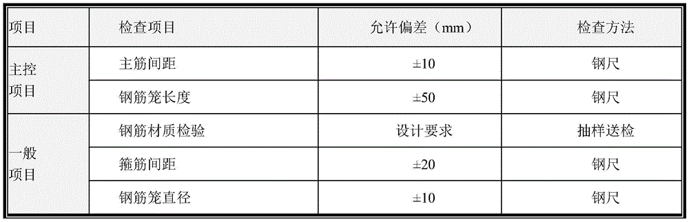
Note that: in the process of hoisting and positioning the steel reinforcement cage: (1) Trial hoisting is carried out on the steel reinforcement cage on site, and if the steel reinforcement cage is damaged during trial hoisting, the hoisting quality is ensured by increasing stiffening ribs; two-point hoisting is adopted when the reinforcement cage is hoisted, so that the reinforcement cage is prevented from generating permanent deformation; (2) The long spiral construction pouring and the lower reinforcement cage need to be integrated, cage insertion is started immediately within three minutes after concrete pouring, time difference is reduced, and cage insertion difficulty is reduced; (3) Forming holes by a long spiral drilling machine, pouring concrete to the ground, then timely cleaning earth surface earthwork, and immediately performing post-inserting reinforcement cage construction; sleeving a steel bar cage qualified in inspection on the steel pipe, and hanging the steel bar cage on a hook arranged on the flange by using a steel wire rope; (4) Because the steel reinforcement cage is longer, the steel reinforcement cage is inserted downwards and two-way verticality observation is required, a two-way line is used for vertically arranging to form a vertical angle, when the verticality deviation is over large, an operator is informed to stop the machine for correction in time, and a cage-descending operator needs to right the steel reinforcement cage to align to the pile position which is poured; (5) In the process of placing the cage, a vibration hammer and the weight of the reinforcement cage must be used for pressing in, the vibration hammer is started when the reinforcement cage cannot be pressed in, the reinforcement cage is prevented from shifting caused by vibration of the vibration hammer, and the insertion speed is preferably controlled to be 1.2-1.5 m/min; (6) After the reinforcement cage is inserted to the designed position, the power supply of the vibration hammer is turned off, then the steel wire rope is picked off, the steel pipe and the vibration hammer are extracted out of the hole, and the vibration hammer is turned on once every 3m in the extraction process so as to ensure the compactness of concrete; (7) installation quality standard and detection method: tolerance deviation of installation of the reinforcement cage: and (3) allowing deviation of installation elevation of the steel reinforcement cage: plus or minus 50mm, and measuring by a level gauge; allowable deviation of thickness of the steel bar protective layer: 50mm, and is controlled by a pilot steel bar welded on the main steel bar.
Note that: the problems and precautions to be taken during the construction of the cast-in-place pile are shown in table 2:
table 2: common problems and precaution of cast-in-place piles
The pile foundation construction by adopting the long spiral bored pile post-dowel construction process has the following advantages: (1) Because the long spiral hole is formed into a dry drilling hole, no slurry is generated, and the environmental pollution is small; (2) Because the whole pile length is spirally drilled in place at one time, the pile forming efficiency is greatly improved, and each drilling machine (with the pile length of about 20 m) can form about 20 to 50 piles per day on average; (3) Because the construction method has high pile forming efficiency and is dry hole operation, the construction consumes electric energy, water energy is less and the cost is lower; (4) Because there is no retaining wall mud, so there is no mud cake around concrete and pile hole, but this, because of the pressure-grouting concrete, so the concrete and pile hole are combined closely, even the stone will imbed the soil body around the pile hole in the concrete, so the peripheral friction resistance of pile increases, because there is no hole bottom deficient soil, so the end resistance of pile is higher than traditional bored concrete pile too; (5) The construction method of pressing concrete by the long-spiral pore-forming pump and inserting the reinforcement cage into the concrete column successfully solves the problem of easy hole collapse and pile breakage after pore forming and water loss under the geological condition of fine sand.
S2, after the construction of the slide rail foundation is finished, prefabricating the special-shaped track beam and installing the rail bearing beam embedded part
The engineering is a land test facility of a key aerial weapon project, has a high starting point, requires the top surface of each bearing platform to be a spatial straight line, allows the deviation of embedded parts of box beams to be 2mm, has 30 groups of embedded parts for each box beam, accumulates 14340 sets of embedded parts, and has large engineering quantity, so the key technology of the engineering is embedded part embedding precision control in engineering measurement and rail bearing beam construction;
construction preparation:
the construction drawing is familiar before construction, technical background and safe background are carried out on construction workers and construction technicians, necessary test detection is carried out on the raw materials entering a field, concrete is tried out, the concrete mixing ratio result is reported to a test supervision engineer for approval, the embedded part entering the field is qualified in check, and relevant construction work is completed;
cleaning the bottom die:
before box girder prefabrication construction, rust, sundries and the like on the surface of a bottom die need to be cleaned, whether the surface of the bottom die is flat or not is checked, and defects are timely treated;
processing and installing steel bars:
the steel bar framework is arranged on a steel bar binding pedestal, the steel bars of various types are positioned according to the designed size, the steel bars of the bottom plate, the framework and the web plate are bound, the binding sequence is from bottom to top, the operation is carried out in sequence, the steel bar interval is checked at any time, and the stirrups are kept to be vertical to the main bars; after the web plate steel bars and the bottom plate steel bars are bound, installing and adjusting the inner template and the outer template, finally binding the top plate steel bars and the wing plate steel bars, and embedding embedded parts;
installing a template:
(1) And (3) outer die installation: the installation, the removal and the hoisting transportation of the outer die are carried out by matching a gantry crane with manpower. Installing side templates after the bottom plate and the web plate steel bars are bound, installing a middle part side template, and then installing two end side templates; the outer side die is inclined according to the design requirement, supported and adjusted through the side die, and fixed by adopting a top counter-pull rod (phi 16) and a bottom counter-pull rod (phi 16); when the template is installed, an adhesive tape with the thickness of 3mm is stuck between the template and the template, so that the sealing property of the template is enhanced, and slurry leakage is avoided; (2) core die installation: the installation of the core mould is carried out after the binding of the reinforcing steel bars of the bottom plate and the reinforcing steel bars of the web plate is finished; when the core mold is installed, a gantry crane is adopted to hoist the core mold into positions in blocks; the core mold falls on a positioning steel bar welded on the bottom plate in advance and is tightly propped and fixed with the outer mold through the steel bar; skylight is reserved on the bottom template and the top template of the core mold, so that air bubbles in the concrete can be discharged conveniently; (3) installing an end template: the end of the two ends of the prefabricated box girder is reserved with wet joint longitudinal steel bars, and the end formworks at the two ends are reserved with steel bar holes according to requirements;
the template should be noted during use for the following points: (1) the template is carefully maintained in the using process, the intact state of the template is ensured in the whole construction process, the surface laitance and rusty spots are polished, and the isolating agent is coated for later use; (2) when the template is assembled, the adhesive tape is added to ensure that the template joint is smooth, tight and does not leak slurry; (3) the templates are inspected in the process of installing the templates and pouring concrete, so that the difficulty in removing the templates due to deformation is prevented; (4) and strictly avoiding collision with the rail bearing beam during loading, unloading and hoisting.
Installing an embedded part:
the engineering is a land test facility for an important air weapon project, and has strict requirements on the position quality of various embedded parts of a rail bearing beam; the straightness of the fastener must satisfy: the vertical direction is +/-2 mm, the horizontal direction is +/-2 mm in a single beam, and the finished line is a spatial straight line; therefore, the position control of the beam body embedded part is a key technology of engineering construction, and the fastener plane layout is shown as 2;
the engineering focuses on controlling the plane and elevation positioning of the embedded bolt A, and the method is as follows: (1) plane position: the bolt A connecting line is a horizontal line after the same beam and all beams are spliced, and the connection of the bolt A at each side of each beam can be controlled to form a line A and a line B and the distance between the line A and the line B shown in the following figure; (2) vertical position: the length L =15 m of the same beam, the distance L = 1m between two adjacent bolts, and according to the ground leveling measurement, the length of the beam can be approximately regarded as the length of an arc relative to half a kilogram of the earth R =6371 kilometer; namely, the elevations of the embedded parts are consistent when the beam body is prefabricated, and the height difference of the two ends can be adjusted when the beam is erected;
the construction quality of the embedded part is mainly controlled by the following links:
(1) Template processing: the method comprises the following steps that before template processing, a designer carefully rechecks a drawing, the position of an embedded part is completely consistent with the design drawing, during the processing, the design is carefully lofted, after the template is processed, a professional technician strictly checks and accepts, and the I-steel position and a fastener positioning device system are used as key points during the checking and accepting, so that if the position error exceeds an allowable range, adjustment and correction are needed in time;
(2) Processing an embedded part: the size of the embedded part is strictly processed according to a drawing, the embedded column needs to be welded with a double-end bolt and then embedded, a steel plate and a reinforcing steel bar as well as the bolt and the steel plate need to be welded, the height of a welding seam is not less than 8mm, the embedded part is processed by a professional manufacturer entrusted by Party A, and the embedded part is used after being accepted by a second time after entering a field;
(3) The method comprises the following steps:
s201, controlling the position of an embedded part of a special-shaped track beam by adopting a fastener positioning and clamping device on a beam body external mold channel steel, simultaneously adding a channel steel 7 on the top of an external mold of a track bearing beam template, wherein one channel steel is arranged at each meter, the position of each channel steel is consistent with the position of the embedded part, and a through hole 71 of an embedded part embedded bolt 8 is reserved on the channel steel;
s202, after the embedded parts are pre-installed on positioning channel steel 7, hoisting the embedded parts to installation positions by using a gantry crane, fixing the embedded parts on an outer template through the positioning channel steel, respectively pulling 1mm steel wires at two ends of the template to perform horizontal direction positioning, ensuring that a steel wire rope is 470mm away from the inner side of an outer mold, the distance between the two steel wires is 1260mm, the steel wires need to be tensioned and cannot be loosened, avoiding measurement errors, aligning central holes of each group of bolts with the steel wires, and then fixing the central holes tightly, so as to ensure the horizontal direction positions of the embedded parts;
s203, after the horizontal position of the embedded part is well positioned, performing high-range positioning, and measuring the top surface elevation of each group of embedded bolts 8 to ensure that the difference error of the position elevation of the embedded part on each beam is less than 1mm;
s204, concrete can not be directly poured after the installation and adjustment of the embedded part are finished, and because a horizontal upper surface template is used for a water groove part between the rail bearing beam platforms, a groove mold is easy to float upwards in the concrete pouring process, 20 steel rails need to be additionally arranged to serve as pressure bars to load the groove mold, and the influence of the floating mold of the groove mold on the position of the embedded part is avoided;
s205, after the concrete pouring is finished, timely finishing and collecting the concrete surface, and completing checking work of the position of the embedded part before the initial setting of the concrete, wherein the checking mode is that if the embedded part is installed, the plane position and elevation adjustment method is adopted, if the displacement, dislocation or inclination needs to be corrected in time;
s206. Concrete curing and finished product protection
After the position of the embedded part is checked to be correct, processing the surrounding disturbed concrete in time, after the concrete is leveled to be grouted, slightly hardening the concrete, and then performing secondary plastering; after the slurry is collected, covering and maintaining the exposed concrete surface by using geotextile, and watering for maintaining; watering for covering and maintaining for at least 7 days, wherein the watering frequency is set to be a degree that the surface of the concrete can be kept in a wet state every day, and a specially-assigned person is assigned to water for maintaining; and the template is dismantled after the concrete strength reaches 2.5MPa, so that the surface and edges and corners are not damaged during dismantling. After the template is dismantled, cleaning mortar and dirt on the surface of the template, maintaining and finishing, coating a release agent on the template, and waiting for the next use; after the template is dismantled, the site is cleaned in time, and the templates are stacked orderly; cleaning the filler of the reserved opening in time after the mold is removed; the exposed part of the bolt is fully coated with grease in the storage process of the rail supporting beam, the PVC sleeve is used for protecting the rail supporting beam, and the stable steel wire rope does not collide with the embedded part as much as possible in the transportation process of the beam so as to avoid inclined deformation.
Wherein: the specific steps of the elevation positioning of the embedded part in the step S203 comprise (1) preparing a steel plate strip with the thickness of 1mm to 5mm in advance, measuring the elevation of the end heads of all embedded bolts A, and adjusting the positions of the rest bolts after taking the arithmetic mean value; (2) If the bolts need to be raised, steel backing plates with corresponding thicknesses are added at the connecting positions of the positioning channel steel and the outer template, if the bolts need to be lowered, the steel backing plates with corresponding thicknesses are added between the positioning channel steel and the embedded part steel plates, and the verticality and the levelness of the installed embedded part are checked by using an instrument;
in the concrete pouring process for the special-shaped track beam in the step S203, the concrete should be poured from one end of the special-shaped track beam to the other end according to the following step (1), the two sides of the special-shaped track beam are simultaneously pushed forwards, the pouring and vibrating are carried out simultaneously, the layered thickness of the poured concrete is about 30cm, and the distance between the front layer and the rear layer is more than 1.5 m; (2) The moving distance of the concrete during vibration cannot exceed 1.5 times of the acting radius of the vibrator, the distance between the vibrator and the side mold is kept to be 5-10 cm, the vibrator is inserted into the lower layer concrete for 5-10 cm, the vibrator is slowly lifted out after being vibrated and compacted, and the phenomenon that the vibrator collides a template, a reinforcing steel bar and other embedded parts to cause the deformation of the template and the displacement of the embedded parts is avoided; (3) The compact mark is that the concrete surface stops sinking and no air bubble appears, and the surface is flat and slurry.
The construction method for processing the inner die, the outer die and the positioning tool adopted by the special-shaped track beam comprises the following steps: (1) The method for finding the overall center line of the embedded part is simplified by directly using the embedded bolt for positioning, the efficiency is greatly improved, the accumulated error in the operation process is reduced, and the precision is higher; (2) The channel steel and the outer mold are used for positioning, so that the influence of the steel bars on the position of the embedded part in the concrete vibrating process is reduced, and the qualified rate of finished products is high; (3) The use of a suspension mold is reduced by one-step molding of the rail bearing beam, pouring is not needed after the initial setting of the concrete at the lower part, and no transverse seam exists among the concrete, so that the integrity of the beam body is better, and the effect is improved; (4) And the secondary checking of the embedded part must be completed before the initial setting of the concrete, otherwise, the accurate checking cannot be carried out, and the requirement on the timeliness is high.
S3, erecting the special-shaped box girder by adopting a method based on bow-string type center line positioning, and assembling the special-shaped box girder and the slide rail foundation
The track extension construction project comprises 7006.6m/1 seats of the track extension bridge engineering, 164.94m/1 seats of the steering bridge engineering, and the upper structure is a 15m reinforced concrete simply-supported box girder; the whole line has 477 bearing platforms, 477 pieces of prefabricated simply supported box beams, 1 piece of cast-in-place box beam and 14340 sleeves; the engineering is a land test facility, has high starting point, requires a line to be a spatial straight line, has a double-track height error of less than 0.2mm, has an error of less than 0.2mm relative to a central line, and has a track gauge of less than 0.2mm; the erection of the box girder requires: the height deviation taking the embedded part steel plate C as a reference is not more than 2mm, and the left-right deviation taking a beam center line formed by the middle points of the connecting lines of the bolts A as a reference is not more than 2mm; the precast beam allowable deviation, the number of inspections and the method are shown in table 3:
table 3: precast beam tolerance, number of inspections and method
The engineering embedded part is processed by a professional manufacturer, the error is controlled within the allowable deviation and passes the acceptance; the deviation between a straight line formed by connecting the bolts A on one side of each beam and a reference line is 2mm, the deviation accords with the design requirement and passes the acceptance, so that the important point of the project is how to position a beam center line formed by connecting the middle points of the bolts A and place the beam center line on a set reference line during beam erection, how to quickly and accurately find the beam center line formed by connecting the middle points of the bolts A as the research direction of the project, and the specific process of the construction process is as follows:
s301, make bow string formula central line positioning tool, including fixed end bolt processing and location bow preparation:
the processing process of the fixed end bolt comprises the following steps:
(1) Two vertical diameter lines are found on a nut matched with the bolt, a line groove with the width of 0.5mm is formed on the edge of the nut along the line, the depth is 1mm, the intersection point of the two lines is the middle point of the nut, and the intersection point position is also the middle point of the bolt after the two lines are sleeved on the bolt; (2) Anchoring a 0.5mm steel wire along a wire slot on one line for fixing, wherein the two outer slots of the unfixed steel wire are connected by the steel wire at the moment, and the steel wire naturally penetrates through the two inner slots to ensure that the fixed steel wire is parallel to the reference line;
the manufacturing process of the positioning bow comprises the following steps:
(1) The deformed steel bar with the diameter of 12mm is used as a bow handle after being bent; (2) Intercepting one section of the tape as a target object, punching holes on two sides, wherein the aperture is not more than 0.5mm, the length of the tape is preferably 10cm, and the middle data is multiples of 5; (3) Taking a steel wire with the thickness of 0.5mm to penetrate into the cut and processed tape measure, and penetrating steel wire clamps at two sides of the tape measure; (4) The steel wire is used as a bow string and fixed on a bow handle, the tool bow is processed, and the length of the bow cannot exceed the distance between the bolts on the outer side.
S302, a bow-string type center line positioning tool is used for positioning, a special-shaped box girder is erected, and the specific process comprises the following steps: (1) Using a total station to find any point on a design central line as a reference point, and erecting a theodolite to enable the direction of the theodolite to be consistent with the direction of the design central line; (2) The positioning nuts are sleeved on the embedded bolts at the symmetrical inner sides, and the positioning nuts are not required to be sleeved too deeply for convenient placement and taking; (3) The bowstring of the tool bow is hung in the wire grooves of the two positioning nuts, the positioning nuts are adjusted to enable the two grooves on the inner side to naturally penetrate through the grooves on the inner side of the tool nut, the steel wire bowstring can not be bent, and the bow is fixed by using a steel wire clamp so as not to shake left and right; (4) Measuring the distance between the two fixed steel wire bowstrings by using a measuring tape, taking the middle value of the upper measuring tape of the bowstring as a target object to move to a middle point after the middle value is taken, wherein the position of the middle value (the target object) of the middle line positioning tape is the middle line position formed by the middle points of the connecting lines of the embedded bolts; (5) And after the beam body is lifted by the hoisting equipment, the target object is coincided with the sighting axis of the positioned theodolite, and then the positioning work is finished.
The tool arch midline positioning method has the advantages that: (1) 1, the operation can be completed by 1 person, and the personnel investment is less than that of the traditional positioning method; (2) the operation method is simple, and the requirement on the personnel technology is not high; (3) The manufacturing method is simple, the cost is low, and the steel bar waste is used; (4) The two ends of the beam can be used simultaneously, so that operators do not need to identify target objects back and forth, and the labor intensity is reduced; (5) The two ends can be rechecked at any time, so that the phenomenon that the displacement of the fixed end cannot be found when the other end of the beam body is moved after one end of the beam is fixed is avoided; (6) The influence of natural factors such as wind power and the like is avoided, and accidental errors are reduced; (7) Offset data can be read at any time, and data reference is provided for lifting personnel; (8) the timeliness is high, and the beam erecting speed can be improved; (9) The operation of operators under the hoisting equipment is avoided, and the safety risk is reduced; (10) The design center line can be found on the accurately positioned beam at any time, and the operation times of the total station can be reduced.
The bow string type center line positioning tool obtained in the step S301 comprises a positioning nut 1, a bow handle 2, a center line positioning ruler 3 and a steel wire bow string 4;
the positioning nut 1 is matched with the embedded bolt A for use, two mutually perpendicular wire grooves 11 passing through the center of a circle are formed in the positioning nut 1, the width of each wire groove 11 is 0.5mm, and the depth of each wire groove 11 is 1mm;
the middle line positioning ruler 3 is arranged in the middle of the steel wire bowstring 4, is connected with the steel wire bowstring 4 through a steel wire clamp 9, is provided with scales, and is 10cm long and the middle data is multiples of 5;
the steel wire bowstring 4 is made of steel wires with the thickness of 0.5mm, two ends, far away from the central line positioning ruler 3, of the steel wire bowstring 4 are connected with the bow handle 2 through the clamping mechanism, and the diameter of the bow handle 2 is 12mm.
Preferably, the bow is provided with trapezoidal clamping groove 21 at 2's both ends connecting portion, clamping mechanism sets up in clamping groove 21, including adjusting bolt 5 and locating piece 6, adjusting bolt 5 runs through the setting of clamping groove 21 both sides curb plate, and with one side curb plate threaded connection of clamping groove 21, all be provided with guide way 22 on the both sides curb plate of clamping groove 21, guide way 22 uses with the cooperation of setting at 6 dorsal guide rails 61 of locating piece, and is in the front side dislocation of two locating pieces 6 is provided with presss from both sides tooth 62, press from both sides tooth 62 and steel wire bow string 4 cooperation use.
Preferably, in order to connect the center line positioning ruler 3 with the steel wire bowstring 4 conveniently, a connecting hole 31 is formed in the center line positioning ruler 3, the connecting hole 31 is matched with the steel wire clamp 9 for use, the steel wire bowstring 4 is clamped, and the center line positioning ruler 3 is connected with the steel wire bowstring 4; the steel wire card 9 include locking strip 91, cassette 92 and locking subassembly, locking strip 91 is for being provided with the flexible locking strip of interior lock tooth 912, is provided with oblique lock tooth 911 at the one end of locking strip 91, is connected with cassette 92 through oblique lock tooth 911, cassette 92 sets up in one side of connecting hole 31, and is provided with the adjustment tank 921 and the mounting groove 922 that communicate each other on cassette 92, locking subassembly movable mounting is in mounting groove 922.
Preferably, the locking assembly comprises a locking block 93, a first spring 94 and a limiting member 95, the locking block 93 is movably mounted in the mounting groove 922, a latch is arranged at the lower end of the locking block 93, the latch extends out of the adjusting groove 921 to be matched with the inner latch 912 for use, so as to lock the locking bar 91, the first springs 94 are symmetrically arranged on the guide posts 931 at two sides of the tail end of the locking block 93, so as to support the locking block 93, and the latch at the lower end of the locking block 93 and the inner latch 912 realize locking; the limiting pieces 95 are arranged on two sides of the adjusting block at the tail end of the locking piece 93, the second spring 96 is arranged at the tail of the limiting piece 95, the locking piece 93 is fixed by the limiting piece 95 so as to be adjustable in the longitudinal direction, when the steel wire bow string fixing device is used, the steel wire bow string 4 is placed on one side of the connecting hole 31 far away from one side of the clamping seat 92, then the free end of the locking strip 91 penetrates through the adjusting groove 921 and is pulled, so that the locking strip 91 locks the steel wire bow string 4, and the connection of the midline positioning ruler 3 and the steel wire bow string 4 is completed; when the bowstring 4 needs to be removed, the locking piece 93 is moved backward by adjusting the wrench.
The achievement of the special-shaped box girder erection construction process based on the bow-string type center line positioning method is as follows:
(1) The project has a contract construction period of 350 days, an actual construction period of 180 days, an original planned girder erection of 120 days and a girder adjustment of 30 days, and the method for positioning the center line by using a tool is simple, convenient and efficient, and the actual girder erection and girder adjustment share 90 days, thereby obtaining significant economic and social benefits in the aspects of cost and work efficiency improvement.
The specific benefit analysis is shown in the following table:
table 4: economic benefit analysis table
(2) Economic benefits
The construction method for erecting the track-supporting beam by using the tool method for central line positioning is simple, convenient and efficient, the actual beam erecting and beam adjusting share 90 days, the investment of personnel and machinery is effectively reduced, the cost expenditure is saved by 104 ten thousand yuan, and economic benefits with high efficiency are obtained in the aspects of cost and work efficiency;
the method comprises the following specific steps:
and crane leasing saves: 6.5 ten thousand yuan/station/month × 2 station × 2 month =26 ten thousand yuan;
and (3) renting the gantry crane saves: 4 ten thousand yuan/station/month × 1 station × 2 month =8 ten thousand yuan;
project original plan configuration erector 5, actual erection 3, balance: 5000 yuan/person/month × 2 person × 5 month =5 ten thousand yuan;
saving project management cost: 9000 yuan/person/month × 12 persons × 6 months =65 ten thousand yuan;
newly increasing profit: 26 ten thousand yuan +8 ten thousand yuan +5 ten thousand yuan +65 ten thousand yuan =104 ten thousand yuan.
The foregoing shows and describes the general principles, principal features, and advantages of the invention. It will be understood by those skilled in the art that the present invention is not limited to the embodiments described above, which are described in the specification and illustrated only to illustrate the principle of the present invention, but that various changes and modifications may be made therein without departing from the spirit and scope of the present invention, which fall within the scope of the invention as claimed. The scope of the invention is defined by the appended claims and equivalents thereof.