CN111395382A - Prefabricated foundation for power transmission engineering - Google Patents
Prefabricated foundation for power transmission engineering Download PDFInfo
- Publication number
- CN111395382A CN111395382A CN202010196139.3A CN202010196139A CN111395382A CN 111395382 A CN111395382 A CN 111395382A CN 202010196139 A CN202010196139 A CN 202010196139A CN 111395382 A CN111395382 A CN 111395382A
- Authority
- CN
- China
- Prior art keywords
- foundation
- base
- prefabricated
- power transmission
- tower
- Prior art date
- Legal status (The legal status is an assumption and is not a legal conclusion. Google has not performed a legal analysis and makes no representation as to the accuracy of the status listed.)
- Pending
Links
Images


Classifications
-
- E—FIXED CONSTRUCTIONS
- E02—HYDRAULIC ENGINEERING; FOUNDATIONS; SOIL SHIFTING
- E02D—FOUNDATIONS; EXCAVATIONS; EMBANKMENTS; UNDERGROUND OR UNDERWATER STRUCTURES
- E02D27/00—Foundations as substructures
- E02D27/32—Foundations for special purposes
- E02D27/42—Foundations for poles, masts or chimneys
Abstract
The invention discloses a prefabricated foundation for power transmission engineering, which comprises a foundation upright post, a foundation base and a foundation, wherein the foundation upright post is arranged on the foundation base and is provided with a foundation main rib and a foundation bolt, and the upper end of the foundation bolt is exposed out of the upper surface of the foundation upright post and is used for connecting an iron tower; the base is provided with rings, and the ring part of each ring is exposed out of the upper surface of the base and is connected with a crane through a connecting piece. The foundation of the power transmission engineering is designed to be a prefabricated foundation, the manufacturing of the concrete foundation is completed in a factory in a preposed manner, formwork supporting, casting and maintenance are intensively performed, process control and maintenance environment can be strictly controlled, cost can be greatly saved, the quality of foundation finished products is improved, 28-day maintenance construction period is shortened, 80% of construction operation time of a site can be reduced, personnel can get on and off a foundation pit, safety risks of the personnel operating in the foundation pit are avoided, pollution of the concrete to the environment is avoided, the mechanization degree of the construction site is improved, and the controllability of the construction period is realized. In addition, the prefabricated foundation is convenient to transport and install.
Description
Technical Field
The invention relates to the technical field of power construction, in particular to a prefabricated foundation for power transmission engineering.
Background
The conventional foundation refers to a load-bearing structure below the ground of a building, such as a foundation pit, a bearing platform, a frame column, a ground beam and the like, and is an enlarged part of a wall or a column of the building in the ground, and the load-bearing structure is used for bearing loads transmitted by an upper structure of the building and transmitting the loads and the loads to a foundation together with self weight. In the existing power transmission engineering, a foundation needs to be arranged at the bottom of the iron tower when the iron tower is erected, so that the iron tower is more stably installed. In the prior art, the foundation is generally poured on site, and the foundation for pouring on site is based on the traditional construction process: the foundation construction is carried out firstly, and then the tower is assembled on the ground, so that the construction process is high in cost, long in construction period and low in construction efficiency due to the adoption of the foundation cast in situ.
Disclosure of Invention
The invention aims to overcome the defects of the prior art and provide a prefabricated foundation for power transmission engineering.
In order to achieve the above purpose, the invention provides the following technical scheme:
a prefabricated foundation for power transmission engineering, said prefabricated foundation being a reinforced concrete structure comprising: the prefabricated foundation is a reinforced concrete structure, and comprises: a foundation base and a foundation column; the foundation column is arranged on the foundation base, a foundation main rib is arranged in the foundation column, a foundation bolt is further arranged in the foundation column, and the upper end of the foundation bolt is exposed out of the upper surface of the foundation column and is used for being connected with an iron tower of the power transmission project; the base is used for supporting the base upright post, the base is provided with a lifting ring, the ring part of the lifting ring is exposed out of the upper surface of the base, and the lifting ring is used for being connected with a crane through a connecting piece.
Furthermore, the hoisting ring is coated with epoxy zinc-rich primer and epoxy coal tar pitch finish.
Furthermore, the number of rings is 4, and 4 rings are along the circumference evenly distributed of basic base.
Furthermore, the part of the foundation base which is not contacted with the foundation upright post is arranged to be in a slope shape.
Further, a platform is arranged on the foundation base and used for arranging the foundation upright post; a downward slope is provided along the edge of the platform to the outside.
Further, the upper end of the foundation column is provided with a protective cap, and the protective cap adopts concrete to protect the foundation bolt.
Furthermore, the connecting piece is a connecting rope or a connecting belt.
Further, the quantity of basis owner muscle is many, many the basis owner muscle is followed the circumference interval of foundation stand sets up, the basis owner muscle vertically sets up and extends to in the basic base, many the basis owner muscle forms basic owner muscle group, follows the circumference of foundation stand is in be provided with outer stirrup and interior stirrup on the basis owner muscle group.
Furthermore, the upper portion and the lower part of base are provided with main muscle and lower main muscle respectively, go up main muscle with lower main muscle all is used for bearing the pulling force and the pressure that prefabricated basis received, go up main muscle with be provided with between the main muscle down rings.
Furthermore, still be provided with the upright muscle in the basic base, the upright muscle is triangle ring-shaped, the apex angle portion of upright muscle with go up the main muscle and be connected, the bottom limit portion of upright muscle with the main muscle is connected down.
Compared with the closest prior art, the technical scheme provided by the invention has the following beneficial effects:
the invention provides a prefabricated foundation for power transmission engineering, which is characterized in that the foundation of the power transmission engineering is designed into the prefabricated foundation, so that the manufacturing of a concrete foundation is completed in a factory, formwork support, casting and maintenance are intensively performed, the process control and the maintenance environment can be strictly controlled, the cost can be greatly saved, the quality of a foundation finished product is improved, the maintenance period of 28 days is shortened, the construction operation time of 80 percent on site can be reduced, personnel are prevented from going up and down a foundation pit, the safety risk of the personnel operating in the foundation pit is avoided, the pollution of concrete to the environment is avoided, the mechanization degree of the construction site is improved, and the controllability of the construction period is realized.
In addition, the upper main rib and the lower main rib are respectively arranged at the upper part and the lower part of the foundation base and are used for bearing the tensile force and the pressure of the prefabricated foundation; the vertical ribs are arranged between the upper main ribs and the lower main ribs and used for conducting the force borne by the hoisting; and a lifting ring is also arranged between the upper main rib and the lower main rib, and the ring part of the lifting ring is exposed out of the upper surface of the foundation base and is used for being connected with a crane through a connecting piece so as to be convenient for hoisting and transporting the foundation. Meanwhile, the foundation base is designed into a slope shape, so that the use amount of reinforcing steel bars and concrete of a bottom plate is reduced, the weight of the foundation is reduced, the transportation and the construction are convenient, and the foundation is lighter and more economical.
Drawings
FIG. 1 is a cross-sectional view of a prefabricated foundation of the present invention;
FIG. 2 is an elevational view of the prefabricated foundation of the present invention;
FIG. 3 is a flow chart of the construction method of the present invention;
FIG. 4 is a schematic diagram of the repeated pit detection in the embodiment of the present invention;
FIG. 5 is a layout view of a construction site according to an embodiment of the present invention;
FIG. 6 is a schematic diagram of excavation of a foundation pit according to an embodiment of the present invention;
fig. 7 is a layout diagram of a positioning device according to an embodiment of the present invention.
Wherein, 1, a protective cap; 2. anchor bolts; 3. a basic main reinforcement; 4. a base concrete; 5. a basic outer stirrup; 6. a foundation inner stirrup; 7. upper main ribs; 8. a lower main rib; 9. erecting ribs; 10. a lifting ring.
Detailed Description
The present invention will be described in detail below with reference to the embodiments with reference to the attached drawings. It should be noted that the embodiments and features of the embodiments may be combined with each other without conflict.
As shown in fig. 1 and fig. 2, which are a cross-sectional view and an elevation view of the prefabricated foundation in this embodiment, the prefabricated foundation in this embodiment is a reinforced concrete structure, and the foundation concrete 4 has tensile, compressive, bending and shearing properties after being hardened to bear all forces of the foundation and simultaneously has the function of protecting the steel bars from corrosion; the prefabricated foundation comprises a foundation base and a foundation upright post arranged on the foundation base, wherein a platform is arranged in the center area of the foundation base and is used for arranging the foundation upright post; a downward slope is arranged along the edge of the platform towards the outside.
The foundation column is internally provided with a foundation main rib group, the foundation main rib group comprises a plurality of foundation main ribs 3 arranged at intervals along the circumferential direction of the foundation column, and the foundation main ribs 3 are used for bearing the tensile force and the pressure of the foundation; as shown in fig. 1, the foundation main reinforcement 3 is longitudinally arranged and extended into the foundation base, and the foundation main reinforcement group is provided with a foundation outer stirrup 5 and a foundation inner stirrup 6 along the circumferential direction of the foundation column, wherein the foundation outer stirrup 5 is used for meeting the shear strength of an inclined section and connecting the tensioned main reinforcement and the concrete in a compression zone to work together; the hooping 6 in the foundation plays a role in stabilizing and preventing the foundation from being dragged during pouring.
The foundation column is also provided with foundation bolts 2, the upper ends of the foundation bolts 2 are exposed out of the upper surface of the foundation column, and the foundation column is used for being connected with an iron tower of a power transmission project and has tensile capacity; the upper end of the foundation bolt 2 is provided with a protective cap 1, the protective cap 1 is used for protecting the foundation bolt, and the foundation bolt is hidden in a square concrete block by concrete and is connected with the top surface of a foundation.
An upper main rib 7 and a lower main rib 8 are respectively arranged at the upper part and the lower part of the base, the upper main rib 7 is a bearing rib, the upper main rib is a reinforcing steel bar configured at the upper side of the base, the lower main rib 8 is a bearing rib, the lower main rib is a reinforcing steel bar configured at the lower side of the base, the upper main rib 7 and the lower main rib 8 are both used for bearing the tensile force and the pressure applied to the prefabricated base, a hanging ring 10 is arranged between the upper main rib 7 and the lower main rib 8, the ring part of the hanging ring 10 is exposed out of the upper surface of the base, the hanging ring 10 is used for being connected with a crane through a connecting piece, and; in this embodiment, the number of the lifting rings 10 is 4, the 4 lifting rings are uniformly distributed along the circumferential direction of the base, and each lifting ring is coated with epoxy zinc-rich primer and epoxy coal tar pitch finish paint to prevent corrosion. In order to avoid the connecting piece from touching the foundation column in the hoisting process, the position of each hoisting ring on the horizontal plane is respectively positioned on the central line of two adjacent foundation bolts in the circumferential direction of the foundation column.
A vertical rib 9 is also arranged between the upper main rib 7 and the lower main rib 8 in the foundation base, and the vertical rib 9 is in a triangular ring shape and is used for transmitting the force borne by hoisting; the top corner of the vertical rib 9 is connected with the upper main rib 7 connected with the hanging ring 10, and the bottom edge of the vertical rib 9 is connected with the lower main rib 8.
The position that does not contact with the foundation column on the foundation base in this embodiment sets up to slope form, designs into board foundation promptly, also can set up to the step foundation in other embodiments, but traditional cast-in-place step foundation base does not have the reinforcing bar, and transportation and hoist are considered to prefabricated foundation in this embodiment, so adopt the form of base plus reinforcing bar to satisfy the intensity requirement of transportation and hoist to the foundation. In addition, through the contrast, the plate-type prefabricated foundation is lighter and more economical than the step prefabricated foundation, can reduce the step quantity, reduces the use amount of bottom plate reinforcing steel bars and concrete, lightens the weight of the foundation, and is convenient to transport and construct. The reduction of the concrete consumption is a main factor for reducing the weight of the prefabricated foundation, and the concrete consumption is less than that of a cast-in-place foundation due to the fact that the number of steps and the whole burial depth of the prefabricated foundation are reduced. Meanwhile, the strength calculation of the prefabricated foundation meets the regulations of overhead power transmission line foundation design technical rules and building structure load specifications, so that the performance and parameters of the prefabricated foundation are not influenced by the reduction of the weight. Preferably, the upper portion of the base is in a shape of a truncated pyramid, such as a truncated pyramid, and more preferably a truncated pyramid, in a longitudinal section of the base, a ratio of a first pitch to a second pitch is (3.5-4.5)/1, the first pitch is a pitch between an edge of a lower surface of the upper portion and an edge of an upper surface of the upper portion on a horizontal projection plane, and the second pitch is a pitch between the edge of the upper surface of the upper portion and the base pillar.
In addition, as shown in fig. 1, in this embodiment, the height of the slope on the base is 200mm, and the height of the slope edge vertically downward is also 200mm, and the ratio of the two is preferably 1: 1; the bottom of the base is a cube with the side length of 2200mm and the height of 100mm, and the horizontal distance between the edge of the slope and the edge of the cube is 100mm, so that the total height of the base is 500 mm; the height of the foundation upright post is 1700mm, and the ratio of the height of the foundation base to the height of the foundation upright post is 5: 17.
The foundation of the power transmission engineering is designed to be a prefabricated foundation, the manufacturing of the concrete foundation is completed in a factory in a preposed manner, formwork supporting, casting and maintenance are intensively performed, process control and maintenance environment can be strictly controlled, cost can be greatly saved, the quality of foundation finished products is improved, 28-day maintenance construction period is shortened, 80% of construction operation time of a site can be reduced, personnel can get on and off a foundation pit, safety risks of the personnel operating in the foundation pit are avoided, pollution of the concrete to the environment is avoided, the mechanization degree of the construction site is improved, and the controllability of the construction period is realized.
In addition, the upper main rib and the lower main rib are respectively arranged at the upper part and the lower part of the foundation base and are used for bearing the tensile force and the pressure of the prefabricated foundation; the vertical ribs are arranged between the upper main ribs and the lower main ribs and used for conducting the force borne by the hoisting; and a lifting ring is also arranged between the upper main rib and the lower main rib, and the ring part of the lifting ring is exposed out of the upper surface of the foundation base and is used for being connected with a crane through a connecting piece so as to be convenient for hoisting and transporting the foundation. Meanwhile, the foundation base is designed into a slope shape, so that the use amount of reinforcing steel bars and concrete of a bottom plate is reduced, the weight of the foundation is reduced, the transportation and the construction are convenient, and the foundation is lighter and more economical.
The tower information of the iron tower in this embodiment is shown in table 1.
TABLE 1 Pole and Tower information

In the embodiment, the concrete information is shown in Table 2, fc is the designed value of the compressive strength of the concrete axle center; ft is the design value of the tensile strength of the concrete axle center; ec is the modulus of elasticity of concrete.
TABLE 2 concrete
| Location of a body part | Strength grade | fc | ft | Ec | Poisson ratio |
| Foundation | C25 | 11.90 | 1.27 | 2.80E+04 | 0.2 |
The information of the steel bars and the steel materials in this embodiment is shown in table 3. Fy is the design value of the tensile strength of the steel bar; fy' is the designed value of the compressive strength of the steel; and Es is the elastic modulus and the compression modulus equivalent value of the steel bar.
TABLE 3 reinforcing bars and steels
| Location of a body part | Species of | fy | f'y | Es | Form factor | c |
| Column main reinforcement | HRB400 | 360 | 360 | 2.00E+05 | 0.14 | 40 |
| Plate main rib | HPB300 | 270 | 270 | 2.10E+05 | 0.16 | 40 |
| Stirrup | HPB300 | 270 | 270 | 2.10E+05 | 0.16 | -- |
The hydrological and geological data information in this example is shown in table 4.
TABLE 4 geological parameters
| No. | t | γ | γe | Cw | Cd | Dcri | | α | Name | |
| 1 | 6.42 | 19.000 | 10.000 | 0.500 | 2.000 | 3.00 | 100 | 10 | Silt (slightly dense) | |
| 2 | 1.20 | 18.000 | 10.000 | 0.300 | 1.600 | 3.00 | 100 | 15 | Silt (Zhongmi) | |
| 3 | 3.34 | 19.000 | 10.000 | 0.300 | 1.600 | 1.50 | 110 | 15 | Cohesive soil (Soft plastic) |
The method is characterized in that the underground water is injected, the influence of the underground water is considered, the high water level is-1.60 m, the low water level is-3.60 m, t is the thickness of a soil layer in unit m, gamma is the soil weight in unit kN/m3, gamma e is the soil floating weight in unit kN/m3, Cw is a width correction parameter, Cd is a depth correction parameter, Dcri is the critical depth in unit m, Qult is the foundation bearing capacity in unit kPa, and α is the calculation pulling angle in unit degree.
The basic force information in this example is shown in table 5. Fx/Fy/Fz is the base force in the X/Y/Z direction, respectively.
TABLE 5 basic force

The basic size information in this embodiment is as shown in tables 6 and 7.
TABLE 6 summary information

TABLE 7 step and floor dimensions
| Serial number | Height | Width of upper end B | Upper end width L | Lower |
| 1 | 0.20 | 0.80 | 0.80 | 2.00 |
| 2 | 0.20 | 2.00 | 2.00 | 2.00 |
Reinforcing bars of the foundation slab: 1 st stage: the number of the upper ends is 12, the diameter of the upper ends is 10mm, the number of the lower ends is 0, and the diameter of the lower ends is 0 mm;
2, 2 nd stage: the number of the upper ends is 0, the diameter of the upper ends is 0mm, the number of the lower ends is 12, and the diameter of the lower ends is 12 mm.
First, basic stable calculation
1. Pull-up stable calculation
Calculating according to a soil weight method: [ T ] ═ 1.00 × 18.471 × 1.0 ═ 9.04-0.00-0.96) +32.952 ═ 182.305kN
Wherein: ht is 1.700 m; hc is 6.000 m;
te × gamma f (126.800 × 1.100.100 ═ 139.480) < [ T ] (182.305kN), and the test is passed through calculation and verification on the basis of the above.
2. Calculation of depression stability
G0 ═ 19.0 ═ 19.90 × (2.00) - (1.756) ═ 111.036kN (considering anhydrous)
fa/γrf=[100+0.50*10.00*(3.00-3)+2.0*19.0*(1.90-0.5)]/0.75=204.267kPa;
1.2xfa/γrf=245.120kPa;
P=[F+γG*(Qf+G0)]/A=[173.000+1.2*(43.872+111.036)]/4.000=89.722kPa;
Pmin=P-(Mx/Wx+My/Wy)=89.722-(35.70/1.333+31.50/1.333)=39.322kPa;
Pmax=P+Mx/Wx+My/Wy=89.722+(35.7/1.333+31.5/1.333)=140.122kPa;
P < ═ fa/gamma rf, Pmax < ═ 1.2 fa/gamma rf, and the base depression calculation check pass.
Second, the normal section bearing capacity of the concrete member
1. Step 1X-X section
F/Ah+Ms/(y1*W0)=105.05/4.00+26.60/(1.20*1.3333)=42.87;
F/Ah+Ms/(y1*W0)=105.05/4.00+22.80/(1.20*1.3333)=40.50;
42.870<749.3, the tension member checks through;
F/Ah+Ms/(y1*W0)=-197.67/4.00+32.30/(1.20*1.3333)=-29.25;
F/Ah+Ms/(y1*W0)=-197.67/4.00+28.50/(1.20*1.3333)=-31.62;
31.624<749.3, the compression member checked through.
2. Calculation of normal section bearing capacity of reinforced concrete bottom plate
Basic acting force: fz-126.800 kN, Fx-12.000 kN, Fy-14.000 kN, Mx-0.000 kn.m, and My-0.000 kn.m;
bending moment Mx about X-axis (Ny ═ (H + H1) + Mx
=14.000*(1.900+0.200)+0.000=29.400kN.m;
Bending moment about Y-axis My ═ Nx (H + H1) + My
=12.000*(1.900+0.200)+0.000=25.200kN.m;
Tpmax=T/(B^2-B0^2)+6*(Mx+My)*B/[B^4-B0^4]=126.800/(2.000^2-0.600^2)+6*(29.400+25.200)*2.000/[2.0^4-0.6^4]=76.120kPa;
Tpc=T/(B^2-B0^2)+6*(Mx+My)*B0/[B^4-B0^4]=126.800/(2.0^2-0.6^2)+6*(29.400+25.200)*0.6/[2.0^4-0.6^4]=47.220kPa;
Tp=(Tpmax+Tpc)/2=(76.120+47.220)/2=61.670kPa;
The upper bending Mt1 ═ Tp (B-B0) ^2 ^ (2 ^ B + B0)/24
=61.670*(2.0-0.6)^2*(2*2.0+0.6)/24=23.167kN.m;
The eccentricity px is My/T/(1+ B0^2/B ^2) ═ 0.182 m;
the eccentricity py is Mx/T/(1+ B0^2/B ^2) ═ 0.213 m;
the eccentricity E (0.21) < ═ B/6, and the normal section bearing capacity of the reinforced concrete bottom plate is calculated and checked to pass;
basic acting force: fz 173.000kN, Fx 15.000kN, Fy 17.000kN, Mx 0.000kN, My 0.000 kn.m;
bending moment Mx about X-axis (Ny ═ (H + H1) + Mx
=17.000*(1.900+0.200)+0.000=35.700kN.m;
Bending moment about Y-axis My ═ Nx (H + H1) + My
=15.000*(1.900+0.200)+0.000=31.500kN.m;
Npmax=N/(B*B)+(Mx+My)/(B^3/6)=173.000/(2.000*2.000)+(35.700+31.500)/(2.000^3/6)=93.650kPa;
Npc=N/(B*B)+(Mx+My)*(B0/B)/(B^3/6)=173.000/(2.000*2.000)+(35.700+31.500)*(0.600/2.000)/(2.000^3/6)=58.370kPa;
Np=(Npmax+Npc)/2=(93.650+58.370)/2=76.010;
Pressed flexural Mn1 ═ Np ^2 ^ (2 ^ B + B0)/24 ═ 76.010 ^2 ^ (2.000-0.600) ^2 ^ (2 ^ 2.000+0.600)/24 ^ 28.554 kn.m;
eccentricity px is My/N is 0.182m, and eccentricity py is Mx/N is 0.206 m;
and the eccentricity E (0.21) < ═ B/6, and the calculation and check of the bearing capacity of the normal section of the reinforced concrete bottom plate are passed.
3. Checking calculation for anti-punching and shearing
Basic acting force: fz-126.800 kN, Fx-12.000 kN, Fy-14.000 kN, Mx-0.000 kn.m, and My-0.000 kn.m;
bending moment Mx around X axis Ny (H + H1) + Mx 14.000 (1.900+0.200) +0.000 ═ 29.400 kn.m; bending moment about Y axis My ═ Nx ═ (H + H1) + My ═ 12.000 ═ (1.900+0.200) +0.000 ═ 25.200 kn.m;
Tpmax=T/(B^2-B0^2)+6*(Mx+My)*B/[B^4-B0^4]=126.800/(2.000^2-0.600^2)+6*(29.400+25.200)*2.000/[2.000^4-0.600^4]=76.120kPa;
Tpc=T/(B^2-B0^2)+6*(Mx+My)*B0/[B^4-B0^4]=126.800/(2.000^2-0.600^2)+6*(29.400+25.200)*0.6/[2.0^4-0.6^4]=47.220kPa;
shear capacity Qx ═ Tpmax + Tpc (B0+ B) × (B-B0)/8 ═ 76.120+47.220 ═ 0.600+2.000 ═ 2.000 (2.000-0.600)/8 ═ 56.120 kN;
shear capacity tolerance Qxr ═ 0.4 × {1-0.5 × [ h3/(h2+ h3) ] (1-B0/B) } × (h2+ h3-at) × (0.4 { (1-0.5 × [0.20/(0.20+0.20) ] (1-0.60/2.00) } × (0.20+0.20-0.04) } 1.27 ═ 1E3 301.752 kN;
qx < ═ Qxr, the baseplate shear bearing capacity check is passed;
basic acting force: fz 173.000kN, Fx 15.000kN, Fy 17.000kN, Mx 0.000kN, My 0.000 kn.m;
bending moment Mx around X axis Ny (H + H1) + Mx 17.000 (1.900+0.200) +0.000 ═ 35.700 kn.m;
bending moment about Y axis My ═ Nx ═ (H + H1) + My ═ 15.000 ═ (1.900+0.200) +0.000 ═ 31.500 kn.m;
Npmax=N/(B*B)+(Mx+My)/(B^3/6)=173.000/(2.000*2.000)+(35.700+31.500)/(2.000^3/6)=93.650kPa;
punching bearing capacity CQ ═ Npmax [ (B0+2 × h2+2 × h3+ B)/2] × [ (B-B0)/2-h2-h3] ═ 93.650 × [ (0.600+2 × 0.200+2.000) ]/2) [ (2.000-0.600)/2-0.200-0.200) ]/47.761 kN;
punching load capacity tolerance CQR 0.7 × Bhp × ft 1000 × h2+ h3-at (B0+ h2+ h3) ═ 0.7 × 1.000 × 1.270 × 1000 (0.200+0.200-0.040) (0.60+0.20+0.20) ═ 320.040 kN;
and CQ & lt is CQR, and the punching bearing capacity of the bottom plate is checked to pass.
The rectangular main column normal section bearing capacity in this embodiment is as shown in tables 8 and 9.
TABLE 8 rectangular Cross-section Reinforcement calculation


TABLE 9 reinforcement calculation results

The oblique section bearing capacity of the main column in this embodiment is shown in table 10.
TABLE 10 main column oblique section bearing capacity

The cross-sectional area Asv of the dual-limb stirrup is 2 (pi (d)/4) is 56.55mm ^2, and h0 is 0.560md is 6 mm;
the stirrup spacing s is 180mm, the main column width b is 600mm, ft is 1.27MPa, and fy is 270 MPa;
v17.000 kN < Vcs 246.301kN, verified.
Reinforcing bars of the bottom plate, wherein the diameter Dbt of the reinforcing bars of the upper bottom plate is 10mm, and the number Ngt of the reinforcing bars of the upper bottom plate is 12; the diameter Dbb of the lower bottom plate reinforcement is 12mm, and the number Ngn of the lower bottom plate reinforcement is 12; checking the upper end reinforcement area (9.425cm ^2> -7.280 cm ^2), and passing the verification; checking the area of the lower reinforcement (13.572cm ^2> -11.200 cm ^2), and passing the checking; the bottom plate reinforcement checking calculation is passed.
The anchor bolts in this example were calculated as in Table 11.
TABLE 11 Foundation bolt Calculations
| Specification of | Number of | Distance between each other | Grade | Pitch of thread | Cross sectional area of | Design value of strength | Allowable tension | |
| M36 | ||||||||
| 4 | 200 | Q235 steel | 4.00 | 816.7 | 160 | 130.676 | 1260 |
The basic stability calculation includes:
calculating the pull-up stability (by adopting a soil weight method):
γf*TE≤γE*γs*γθ1*(Vt-△Vt-V0)+Gf
γf*TE=126.800×1.100=139.480kN
γ E γ s γ θ 1 (Vt- △ Vt-V0) + Gf 1.00 18.471 1.0 (9.04-0.00-0.96) +32.952 182.305kN, 139.48 ≦ 182.305, indicating that the calculation is feasible.
And (3) calculating the pressing stability:
the pressure at the base bottom surface should conform to the following equation:
gamma rf P is less than or equal to fa (when axial load acts); gamma rf Pmax is less than or equal to 1.2 fa when eccentric load acts;
the pressure at the base bottom surface can be determined according to the following formula:
(when the axial load acts) P ═ F + γ GG)/a; (when eccentric load is applied) Pmax ═ F + gamma G)/A + MX/WY + MY/WX;
g0 ═ 19.0 ═ (1.90 × (2.00) to (1.756) ═ 111.036kN (considered anhydrous);
fa/γrf=[100.0+0.50*10.0*(3.00-3)+2.00*19.0*(1.90-0.5)]/0.75=204.267kPa;
1.2xfa/γrf=245.120kPa;
P=[173.000+1.2*(43.872+111.036)]/4.000=89.722kPa;
Pmin=89.722-(35.700/1.333+31.500/1.333)=39.322kPa;
Pmax=89.722+(35.700/1.333+31.500/1.333)=140.122kPa;
89.722 is 204.267, the basic axle center is pressed downwards to meet the requirement;
140.122 is 245.12, the basic eccentric pressing meets the requirement.
The concrete member normal section bearing capacity calculation comprises the concrete tension member normal section bearing capacity:
TE/Ah+Ms/(γ1*W0)≤0.59*ft;
105.05/4.00+26.60/(1.20*1.3333)=42.87;
105.05/4.00+22.80/(1.20*1.3333)=40.50;
42.870<749.3, the tension member is satisfactory;
-197.67/4.00+32.30/(1.20*1.3333)=-29.25;
-197.67/4.00+28.50/(1.20*1.3333)=-31.62;
31.624<749.3, the compression member meets the requirements.
Wherein fc is designed value of concrete axial compressive strength, ft is designed value of concrete axial tensile strength, Ec is concrete elastic modulus, Fy is designed value of reinforcing steel bar tensile strength, Fy' is designed value of steel bar compressive strength, Es is designed value of reinforcing steel bar elastic modulus and compression modulus equivalent value, Fx/Fy/Fz is basic acting force in X/Y/Z direction, gamma F is basic additional partition coefficient, TE is designed value of basic pull-up, gamma E is horizontal force influence coefficient, gamma s is weighted average height of soil above basic bottom surface, gamma theta 1 is plane slope angle influence coefficient on basic bottom plate, 1 when the angle is not less than 45 degrees, 0.8 when the angle is less than 45 degrees, 0.8 when Vt is volume of soil and foundation in ht depth, △ Vt is micro volume of adjacent foundation influence, V0 is basic volume in ht depth, Gf is self weight of foundation, P is average designed pressure value at bottom surface, Fa is load bearing characteristic value of foundation after correction, gamma adjustment rf is adjusted, 0.75 is adjusted to be base load bearing factor of foundation, and the maximum load bearing factor of foundation is obtained when P is equal to the bottom surface of foundation and the ground, and the load bearing factor of foundation is obtained by taking the sum of vertical load bearing factor of foundation (P is equal to be equal to 1.1.1.1.1.1.1.1.1.1.1.1.1.1.1.1.1.1.1.1.1.1.1.1.1.12) (ii) a Mx and My are respectively designed values (kN m) of moments acting on the base bottom surface in the X and Y directions; wx and Wy are the resisting moments (m) of the base bottom surface around the X and Y axes respectively3) (ii) a Pmin is the design value for the lowest pressure (kPa) at the base floor edge.
The calculation results are shown in tables 12 and 13.
TABLE 12 Stable calculated results
| Computing item | Allowable value | Actual value | Unit of | Safety margin | Conclusion | Working conditions |
| Stable upward pulling | 182.3053 | 139.48 | kN | 23.49% | By passing | |
| Foundation hold-down P | 204.2667 | 89.7224 | kPa | 56.08% | By passing | Working condition 2 |
| Base down pressure Pmax | 245.12 | 140.1224 | kPa | 42.84% | By passing | Working condition 2 |
TABLE 13 calculation of load bearing capacity


Volume of concrete: 1.83m ^3, foundation buried depth: 1.9 m.
The prefabricated foundation in the embodiment is used for a power transmission engineering prefabricated foundation installation and iron tower assembly coherent construction method, and the method comprises the following steps of: step S1, retesting and pit-dividing; step S2, designing a construction plane; step S3, tower assembling on the ground; step S4, excavating a foundation pit; s5, transporting and installing a prefabricated foundation, wherein the prefabricated foundation is formed in a non-construction site; step S6, basic backfilling; step S7, checking and accepting the transferred sequence; and step S8, erecting the whole tower.
In step S1, after the full-line retest, pit-dividing work is performed, pit-dividing measurement is performed according to the set pay-off size, foundation center piles are arranged on two adjacent sides of the pit position, auxiliary piles are arranged at positions corresponding to the pit position, and the foundation center piles and the auxiliary piles are used for hoisting the prefabricated foundation in place and aligning the foundation bolts.
In step S2, the construction work surface of each pylon is planned to be a foundation pit excavation area, an earth piling area, a ground pylon assembly area, and a crane and truck seating area according to the retest pit and the site environment, thereby performing ground pylon assembly construction.
In step S5, a laser positioning instrument is installed according to the position of the center pile of the foundation and the position of the center line of the pit, and the prefabricated foundation is installed according to laser emitted by the laser positioning instrument; the number of the laser positioning instruments is two, the two laser positioning instruments are respectively arranged on two adjacent sides of the pit position, and a connecting line of each laser positioning instrument and a basic center column of the corresponding side of the laser positioning instrument is perpendicular to the corresponding side, so that light rays emitted by the two laser positioning instruments are perpendicular to each other; every laser positioning appearance includes 4 laser lamps, launches 4 vertical light after opening the laser lamp, intersects perpendicularly with the 4 vertical light that face the laser positioning appearance transmission of limit setting, and the apex position that corresponds prefabricated basic rag bolt position and basic roof is confirmed according to the position of nodical.
The line production construction method of 'prefabricated foundation installation + integral tower erection' can greatly improve the mechanical construction rate of the foundation and the tower assembly stage, improve the integral construction efficiency by more than 3 times, reduce and avoid 90% of high-altitude operation in the tower assembly process, and really realize 'fully mechanical construction' of line engineering; the investment of labor cost is reduced, and the foundation and tower assembling procedures of the same base iron tower can be controlled in the same growing period of the green seedlings, so that the economical efficiency of line engineering construction is improved to a greater extent.
As shown in fig. 3, each step of the prefabricated foundation installation and iron tower erection coherent construction method in this embodiment specifically includes:
before the method is implemented, step 1 construction preparation is generally required, and the method comprises the following steps:
1.1 personnel preparation
(1) According to the configuration requirements of teams and groups on an operation layer, 4 teams and leaders are configured on site, 4 technical and quality inspectors are configured on site, and 4 field security operators are configured on site (4 teams and groups meet the requirements of continuous operation in a flow mode).
(2) Constructors, crane drivers and commanding setos participating in prefabricated foundation hoisting and iron tower erection need to check up the prefabricated foundation to be qualified, have post-working conditions and receive technical delivery.
(3) The team leader also commands and communicates with the crane driver before construction, so that the field condition is observed together, and the crane driver is explained about the construction process and safety precautions. Commander and crane driver clearly command password and gesture.
1.2 preparation of the technique
(1) The basic strength reaches more than 100% of the design value after the basic engineering passes the acceptance; the sizes of all parts of the foundation are verified to be correct.
(2) Preparing technical data including 'iron tower detail table', iron tower construction drawing, construction scheme and the like.
(3) And the engineering technology responsible personnel organize experienced construction personnel to carry out field investigation and are familiar with the drawing of the iron tower.
(4) And (4) making a technical stock-keeping, wherein all constructors, crane drivers and cable operators must participate. And (5) evaluating the effect after bottom crossing.
1.3 construction machine preparation
(1) Various tools and machines used for assembling the iron tower are required to be assembled according to an attached crane tower assembling tool configuration table, machine inspection data are required to be complete, and the tools and machines can be transported to the site for use after the appearance inspection is qualified. The crane tower assembly tool configuration record contains: tool or implement name, model, quantity. Tools and implements include, but are not limited to: crane, excavator, driving, wire rope cover, shackle, nylon rope, spanner, lumber skid, intercom, suspender, tower chi, laser instrument, surveyor's level, spade.
(2) The necessary safety precautions and appliances should be deployed. The device comprises a safety helmet, a safety belt, a climbing self-locking device, a speed difference self-controller and the like, wherein before each use, appearance inspection is required, and the use is forbidden due to defects such as cracks, rot, damages and the like.
(3) The obstacles influencing the hoisting construction range of the crane are required to be cleaned or avoided by taking measures in advance.
(4) According to the hoisting weight, the hoisting height, the hoisting load of the crane, the operation amplitude and the like, the crane with the corresponding tonnage is selected and used in the attached table. The crane should possess security inspection qualification certificate, permit certificate, should carry out comprehensive inspection to the crane before lifting by crane.
(5) Tools and instruments required by tower assembling are prepared according to the following tool and instrument table, and the tools and instruments can be transported to the site after being tested and qualified through mechanical tests in tool and instrument branch companies or central material stations.
And arranging a safety fence, a responsibility board, a warning board, a friendly notice board, a risk notice board, an emergency rescue route map and the like according to the regulations on the construction site.
Step 2, re-testing and pit-dividing
2.1 construction survey considerations
The used multiplexer utensil of construction measurement: GPS locator, theodolite, sopwith staff, steel ruler, etc. The gauge must be checked before use and errors that exceed standards should be corrected. During the construction measurement, the record is made at any time, the construction record is filled in faithfully, and when the content is found to be out of tolerance or a spanning object is newly added during the line measurement, the construction item part is reported in time so as to be in contact with a design department for solving the problem in time. The central pile of tower position lost individually after pile crossing is designed and should be compensated according to the design data. The distance and elevation measurements between the piles may be relocated using GPS.
2.2 pit division
General requirements for pit separation: and pit separation can be carried out after no problem exists in the full-line retest. And carrying out pit measurement according to specified pay-off size, nailing an auxiliary pile near the pit position so as to hoist the prefabricated foundation in place and align the foundation bolt, and carrying out pay-off on the auxiliary pile to align.
2.3 Foundation pit dividing method
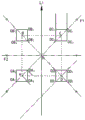
The invention relates to a step foundation tangent tower pit, wherein an iron tower is a square foundation, the square foundation is divided into pits according to diagonal directions, necessary auxiliary piles which are used as construction and quality control are nailed in the pits according to the position of a tower center pile, the measurement precision of the auxiliary piles can meet the requirement of the specification on the construction precision, when the tower center pile cannot be kept in construction, reliable auxiliary piles are nailed and the position and the distance of the auxiliary piles are recorded so as to conveniently recover the tower center pile, a pit opening is drawn in a striking way, as shown in figure 4, a pit dividing positioning principle diagram is shown, the positions of the center pile and the auxiliary piles are determined according to the principle diagram and the data of the size, the heel opening and the like of the foundation in the drawing, as shown in figure 4, O is the center point of the pit, A, B, C, D four foundations are arranged in the pit, L1 is a line center line, F1 and F2 are auxiliary piles, OA is provided with the position1、OA2、OA3、OA4At the four corners of the base A, OB1、OB2、OB3、OB4At four corners of a base B, OC1、OC2、OC3、OC4Four corners of the base C, OD1、OD2、OD3、OD4Four corners of base D.
As shown in fig. 5, each iron tower construction working face is reasonably planned into four areas, such as a foundation pit excavation area, an earthwork stacking area, a ground tower assembling area, a crane and truck positioning area and the like, according to the retest pit division and the field environment, so that the ground tower assembling construction is performed in advance.
4.1 transportation, on-site inspection and checking of Tower materials
(1) The tower material is transported by laying square wood or coating flax, so that direct contact between iron parts, steel wire ropes and the tower material is avoided, and bending of components and abrasion of a zinc coating are prevented.
(2) Before the iron tower is assembled, the tower materials transported to the site must be subjected to quantity counting and quality inspection, so that the tower materials with unqualified quality cannot be used, and the iron tower lacking main materials and key connecting plates and connected with steel packages cannot be assembled.
(3) The various bolts, washers, and pins used in assembly must be complete. When the bolt is used, bolts with different specifications and different levels need to be stacked respectively, and marks are made.
(4) The tower materials are arranged according to the sequence of the tower sections and are respectively stacked on two sides of the tower position, and the lower section is close to the foundation and the upper section is slightly far away when stacking.
4.2 ground group tower
(1) All the components are arranged within the hoisting radius of the crane and follow the following principle: assembling the tower head close to the crane and the foundation side; the tower legs are assembled on the extension line of the crane and the tower head.
(2) Before assembly, whether the tower materials transported to the tower number are complete and correct is checked according to the construction drawing, quality inspection is carried out, the tower materials which do not meet requirements need to be replaced, tools, tower materials and bolts need to be placed reasonably and orderly, and the tower materials are placed according to the segmentation sequence and the serial number of the drawing.
(3) Leveling the site before assembling the tower, removing the barriers, and filling iron tower support skids or grass bags filled with soil, wherein the skids are not too high and are only 0.2m away from the ground.
(4) The material should be moved from top to bottom in the piled tower material, and the material should not be pulled forcibly.
(5) When carrying the tower material, attention should be paid to whether people are around, and more than two people carry the tower material at the same time in a consistent pace and fall together.
(6) The tower body is assembled on the ground and is hoisted after being fastened by bolts.
(7) Before the iron tower is erected, a grounding wire must be buried in advance, and when the grounding wire is not welded, a grounding down-lead is timely installed after the tower is hoisted in place. If the down lead is not welded, a temporary grounding wire is firstly installed.
(8) The assembled hanger must be within the radius that the crane allows for lifting.
(9) The combination of the components should be tight, and the cross components should be installed with corresponding thickness of spacer if there is a gap left at the cross.
(10) When assembling the tower legs of the iron tower, in order to prevent the tower legs from deforming because the two tower legs above the tower legs sag due to the self weight, two lengths between the two tower legs on two vertical surfaces are equal to the length of the iron tower heel, the sand rod with the diameter not less than 150 mm is fixed between the upper tower foot and the lower tower foot, so that the phenomenon of deformation of the tower legs caused by the sagging of the upper tower foot is prevented.
Step 5, excavating foundation pit
As shown in fig. 6, the earth-rock square class releases the outer boundary line of the building positioning according to the drawing, nails the auxiliary pile and pours concrete to protect the pile body so as to avoid collision displacement, and requires supervision and reexamination after self-inspection.
Excavating the underground part of the earthwork twice in place (putting a slope according to the design requirement), and excavating the whole large area by a first layer of large back-hoe; a small back shovel is used for excavation, and because mechanical power is large, in order to prevent the construction machinery from damaging the foundation pit, a construction isolation area is arranged 2m away from the edge of the foundation pit, and the second layer is trimmed manually to clear the bottom.
The foundation pit edge slope-setting ratio is 1: 0.5.
according to construction specifications, mechanical excavation is adopted, 1 excavator is equipped during earthwork excavation, and earthwork excavation is carried out in a mode of manually clearing the bottom, repairing the slope and clearing the groove.
The bottom of the foundation pit is leveled to uniformly measure the depth of the foundation pit on the bottom surface of the foundation, and the deep part is not more than 100 mm. The height difference with the base bottom surface of the base is not more than 5 mm.
And cleaning the groove and checking and accepting after the foundation pit is excavated.
Step 6, transporting, checking and installing the prefabricated foundation
6.1 prefabricated Foundation transportation
In the embodiment, the foundation is finished by binding, erecting, pouring and maintaining the reinforcement, the size of the foundation prefabricated in the factory is basically the same as that of the foundation manufactured on site, the bottom plate of the structure manufactured on site is not provided with the reinforcement, the reinforcement is added to the prefabricated foundation and is connected with the lifting ring, and meanwhile, the foundation is maintained in a unified manner in the factory, so that the pit-dividing maintenance time on site is greatly shortened.
(1) Before basic transportation, a proper, smooth and firm route is selected according to transportation requirements.
(2) The size, quality, quantity and acceptability of the base should be checked carefully on a list before shipping.
(3) All prefabricated foundations of the embodiment are transported flatly, and cannot be transported flatly.
(4) When the foundations are transported horizontally, 100 × 100 flitch blocks must be placed between every two foundations, and the gravity center position of the foundations is located at the center of gravity of a transport vehicle.
(5) The foundations are required to be numbered uniformly according to the tower numbers before transportation, and the self-adhesive labels are uniformly utilized to mark the striking positions on the side faces of the prefabricated foundations.
(6) The transport vechicle establishes rationally to set up the strong point according to basic type, and need to have reliable stable foundation measure, uses the steel wire area to add the fastener and ties up firmly, prevents that the basis is impaired when the transportation.
(7) The vehicle is started slowly, the vehicle runs uniformly, and overspeed, hard turning and emergency braking are strictly prohibited.
(8) In order to ensure the driving safety, safety technology before transportation should be used.
(9) A transportation route: the firm condition of the foundation is checked at each intersection node, a specially-assigned person monitors and checks the road on the vehicle, and the transverse distance between a inspector and a vehicle body is not less than 7 meters (1.2 times of the height after loading) and the communication is kept smooth.
6.2 basic on-site acceptance
Table 14 prefabricated basis acceptance items

TABLE 15 appearance quality requirement of component and inspection method table

The appearance defects refer to the fact that the end of the component is not straight, inclined, has edges and corners missing, has flash and has convex scars. The appearance defects refer to rough surfaces, peeling, sanding and smearing on the surface of the component. The exterior contamination means that the surface of the component is greasy dirt or sticky impurities.
6.3 prefabricated Foundation in-place installation
(1) The crane is located the basis and takes one's place along line direction side, arranges 4 meters apart from the foundation ditch edge.
(2) The first 10 ton truck (1 truck carrying two legs of foundation A, B) to transport the prefabricated foundations enters the field and is in place within the range of crane operation, minimizing the crane elevation and the range of telescoping poles.
(3) According to the position of the center pile and the center line, two laser positioning instruments are installed, laser is turned on, and in the implementation, each basic leg is positioned by using the two laser positioning instruments, and the positioning instruments need to be moved to perform positioning work of the next basic leg.
(4) Hoisting a prefabricated foundation A leg on a truck, slowly entering a foundation pit, installing in-place personnel into the foundation pit when the prefabricated foundation A leg is 0.5 m away from the foundation pit base surface, aligning a laser intersection shot by a laser positioning instrument to install the foundation in place, and after the A leg is installed, withdrawing the foundation pit from the personnel in the foundation pit; then, the leg B is installed according to the same method; and the B-leg installation is completed, the first truck leaves the site, the second truck enters the site, C, D legs are installed in the same sequence, and the prefabricated foundation is installed in place.
As shown in fig. 7, Z1 to Z4 in fig. 7 are basic center piles for determining the position of the positioning instrument; z5 and Z6 are transverse center posts for determining the transverse center line; e1 and E3 are vertical line center piles for determining the vertical center line; d1 and D2 are positioning instruments. The main component of the locator is 4 laser lamps which can also be called laser striping machines. Respectively arranging a positioning instrument on the adjacent sides according to a foundation center pile and an auxiliary pile which are arranged in advance; after the laser lamp is turned on, each positioning instrument emits 4 vertical light rays, the 4 light rays emitted by each positioning instrument are parallel to each other, the light rays emitted by the two positioning instruments are vertically intersected to obtain 16 intersection points, wherein the four middle points are the positions of foundation bolts, and the four outer rings are 4 vertexes of the top surface of the stand column and are vertexes of a central square; in other embodiments, if the requirement on the precision is not high, only the outer 4 intersection points (the intersection points of the base top surfaces) can be determined so as to wait for the coarse adjustment position during installation, and if fine adjustment is needed, the inner 4 positions of the anchor bolts are needed. The foundation bolts are used for connecting the iron tower, so the position of the foundation bolts needs to be accurately set, and when the prefabricated foundation is hoisted and lowered to the preset height, the weight of the prefabricated foundation is measured by tons, and if the prefabricated foundation is adjusted in place once, workers can consume great strength. Through four laser lamps that this application set up, can descend to first coarse adjusting when predetermineeing the height, only according to 4 nodical positions of confirming four angles of basic top surface in the outside, then when descending to the second and predetermineeing the height, fine setting again, only according to four nodical 4 rag bolt positions of confirming of inboard. In addition, if the error of the foundation bolt in the prefabrication process is not considered during coarse adjustment, the foundation bolt is required to be positioned at a proper position of the connecting iron tower at the moment; for preventing the position of the foundation bolt from deviating during prefabrication, the foundation bolt can be directly finely adjusted according to the placement of the intersection point adjusting foundation on the inner side after coarse adjustment, so that the position of the foundation bolt is more accurately set.
Each locator is provided with 4 laser lamps, light rays emitted by the 4 laser lamps are vertical lines and are parallel to each other, two of the light rays are red in the middle, two of the light rays are green on two sides, and the distance between the laser lines emitted by the red laser lamps and the axis of the foundation center pile is the distance between the axis of the foundation bolt and the axis of the foundation center pile; the distance between the laser line emitted by the green laser lamp and the axis of the foundation center pile indicates the distance between the side edge of the top of the upright post and the axis of the foundation center pile. The four laser lamps are divided into: the laser device comprises a first laser lamp, a second laser lamp, a third laser lamp and a fourth laser lamp, wherein the laser lines emitted by the first laser lamp and the fourth laser lamp are consistent in color, if the laser lines are green, the laser devices are used for calibrating four vertex positions of the top of an upright post (or a basic top plate). The laser lines emitted by the second laser lamp and the third laser lamp are consistent in color, and if the laser lines are red, the laser lines are used for calibrating the positions of the four foundation bolts. Second laser lamp and third laser lamp are at the crisscross setting of vertical direction, so can make the distance between the laser line that both launched can reach less distance.
Step 7, foundation checking and backfilling
7.1 basic data check
And after the foundation hoisting is finished, checking the foundation data according to the following table.
TABLE 16 Pre-backfill data verification standards


AB in the table is the distance between the center points of the bases A and B, and the center point of the base A is OA in FIG. 41、OA2、OA3、OA4The center of the enclosed square, the center points of other three bases and so on; BC is the distance between the center points of the foundation B and the foundation C, CD is the distance between the center points of the foundation C and the foundation D, DA is the distance between the center points of the foundation D and the foundation A, AC is the distance between the center points of the foundation A and the foundation C, and BD is the distance between the center points of the foundation B and the foundation D. Generally, an iron tower has four tower legs, each tower leg corresponds to a foundation, and each foundation is provided with four foundation bolts for fixing the tower legs.
7.2 backfill
(1) And (5) backfilling after the foundation is verified, and verifying the follow-up data and preventing and controlling torsion again when 50% of the backfill is performed.
(2) And the foundation backfill needs to recycle the mellow soil. The foundation pit is backfilled by layers and tamped, and backfilled earth is uniformly backfilled around the foundation pier once per 300mm of backfilled earth. An anti-sinking layer is built on the ground of the pithead, and the edge width of the upper part of the anti-sinking layer is not less than that of the pithead. The height is determined according to the soil compaction degree, and the base acceptance is preferably 300-500 mm. After settlement, the materials should be timely filled and tamped. The backfill soil of the pithead should not be lower than the ground when the project is handed over.
(3) After backfilling, the tissues are immediately organized for checking and accepting.
Step 8, checking and accepting the sequence
The sequence-switching acceptance check is a behavior of entity quality acceptance check in a finished stage when processes are switched, the acceptance check can be carried out in the next process if the acceptance check is qualified, namely, the acceptance check work required in a tower-assembling construction stage is switched from a foundation construction stage, and the iron tower can be directly erected integrally because the foundation entity does not need to be maintained and the iron tower is already assembled on the ground.
The tower head of the iron tower is close to the crane about 4 meters away from the crane, the side of the tower foot is extended upwards from the crane and the tower head, four-point crane main hook hoisting steel wire rope binding points are arranged at the connecting plate of the lower beam of the tower head and the crank arm, four-point crane auxiliary hook steel wire rope binding points are arranged on the main materials at two sides of the iron tower 4 meters away from the tower foot and 10 meters away from the tower foot, the working range of the crane is 12 meters, the main arm is 29.7 meters, and the hoisting weight is 4.8 tons, the iron tower is hoisted by using a big hook and a small hook at the same time, the distance between the tower head of the iron tower and the suspension arm is ensured, the big hook is gradually hoisted at the hoisting distance of about 4 meters, the small hook hoisting ensures that the tower foot of the iron tower does not contact with the ground until the whole iron tower is hoisted to more than 45 degrees, the big hook is hoisted, the small hook is loosened and, the crane hook continues to hoist the iron tower and slowly moves to the foundation anchor bolt, an anchor gasket and a nut are installed, the screw thread is roughened after installation is finished, and 1 high-altitude operator climbs the tower and takes off the rope sling.
According to the method, the construction process of firstly assembling the tower on the ground and then constructing the foundation is developed, and the flow line operation construction scheme of 'prefabricated foundation + integral tower erection' is completed by repairing and compiling, so that the flow line operation mode of 'personnel flowing along with the machine, continuous operation of the machine and tight connection of the processes' is guided to be developed on site, the tight connection of 10 processes of 'on-site retesting, pit division positioning, construction plane design, ground tower assembling, foundation pit excavation, prefabricated foundation transportation and installation, grounding installation, foundation backfill tamping, sequence change acceptance and integral tower erection' is realized, the integral construction efficiency of the line foundation and the iron assembly is improved to the maximum extent, the shortest and controllable construction period is realized, the mechanization degree of the construction site is improved, and the site construction risk is reduced.
The line production construction method of 'prefabricated foundation installation + integral tower erection' can greatly improve the mechanical construction rate of the foundation and the tower assembly stage, improve the integral construction efficiency by more than 3 times, reduce and avoid 90% of high-altitude operation in the tower assembly process, and really realize 'fully mechanical construction' of line engineering; the investment of labor cost is reduced, and the foundation and tower assembling procedures of the same base iron tower can be controlled in the same growing period of the green seedlings, so that the economical efficiency of line engineering construction is improved to a greater extent.
The method breaks through the traditional innovative process method, solves the problems of long curing period and poor effect of concrete in winter, overcomes the problem of overlong construction period of foundation and tower assembly of a power transmission project, saves the construction cost and improves the project quality.
Other embodiments of the present technology will be apparent to those skilled in the art from consideration of the specification and practice of the invention disclosed herein. This application is intended to cover any variations, uses, or adaptations of the technology following, in general, the principles of the application and including such departures from the present disclosure as come within known or customary practice within the art to which the technology pertains and as may be applied to the essential features hereinbefore set forth. The specification and examples are to be considered as exemplary only, and the technical scope of the present invention is not limited to the contents of the specification, and must be determined in accordance with the scope of protection of the present application.
It will be understood that the present application is not limited to the precise arrangements described above and shown in the drawings and that various modifications and changes may be made without departing from the scope thereof. The scope of the application is only limited by the content of the appended representative protection scope.
Claims (10)
1. A prefabricated foundation for power transmission engineering, characterized in that the prefabricated foundation is a reinforced concrete structure, comprising: a foundation base and a foundation column;
the foundation column is arranged on the foundation base, a foundation main rib is arranged in the foundation column, a foundation bolt is further arranged in the foundation column, and the upper end of the foundation bolt is exposed out of the upper surface of the foundation column and is used for being connected with an iron tower of the power transmission project;
the base is used for supporting the base upright post, the base is provided with a lifting ring, the ring part of the lifting ring is exposed out of the upper surface of the base, and the lifting ring is used for being connected with a crane through a connecting piece.
2. The prefabricated foundation for power transmission engineering of claim 1 wherein said eye is painted with an epoxy zinc rich primer and an epoxy coal tar pitch topcoat.
3. The prefabricated foundation for power transmission engineering according to claim 1, wherein the number of the lifting rings is 4, and the 4 lifting rings are uniformly distributed along the circumferential direction of the foundation base.
4. The prefabricated foundation for power transmission engineering according to claim 1, wherein the part of the foundation bed not in contact with the foundation columns is provided with a slope.
5. The prefabricated foundation for power transmission engineering according to claim 4, wherein a platform is arranged on the foundation bed, and the platform is used for arranging the foundation column; a downward slope is provided along the edge of the platform to the outside.
6. The prefabricated foundation for power transmission projects according to claim 1, wherein the upper end of the foundation column is provided with a protective cap, and the protective cap protects the anchor bolt with concrete.
7. Prefabricated foundation for the transmission of electricity engineering according to claim 1, characterized in that the connection elements are connection ropes or connection straps.
8. The prefabricated foundation for power transmission engineering according to claim 1, wherein the number of the basic main reinforcements is multiple, multiple basic main reinforcements are arranged at intervals along the circumferential direction of the basic column, the basic main reinforcements are longitudinally arranged and extend into the basic base, the multiple basic main reinforcements form a basic main reinforcement group, and an outer hoop reinforcement and an inner hoop reinforcement are arranged on the basic main reinforcement group along the circumferential direction of the basic column.
9. The prefabricated foundation for power transmission engineering according to claim 1, wherein an upper main rib and a lower main rib are respectively arranged on the upper portion and the lower portion of the foundation base, the upper main rib and the lower main rib are used for bearing the tensile force and the pressure applied to the prefabricated foundation, and the hanging ring is arranged between the upper main rib and the lower main rib.
10. The prefabricated foundation for power transmission engineering according to claim 9, wherein the foundation bed is further provided with an erection rib, the erection rib is in a triangular ring shape, a top corner portion of the erection rib is connected with the upper main rib, and a bottom edge portion of the erection rib is connected with the lower main rib.
Priority Applications (1)
| Application Number | Priority Date | Filing Date | Title |
|---|---|---|---|
| CN202010196139.3A CN111395382A (en) | 2020-03-19 | 2020-03-19 | Prefabricated foundation for power transmission engineering |
Applications Claiming Priority (1)
| Application Number | Priority Date | Filing Date | Title |
|---|---|---|---|
| CN202010196139.3A CN111395382A (en) | 2020-03-19 | 2020-03-19 | Prefabricated foundation for power transmission engineering |
Publications (1)
| Publication Number | Publication Date |
|---|---|
| CN111395382A true CN111395382A (en) | 2020-07-10 |
Family
ID=71434388
Family Applications (1)
| Application Number | Title | Priority Date | Filing Date |
|---|---|---|---|
| CN202010196139.3A Pending CN111395382A (en) | 2020-03-19 | 2020-03-19 | Prefabricated foundation for power transmission engineering |
Country Status (1)
| Country | Link |
|---|---|
| CN (1) | CN111395382A (en) |
Cited By (2)
| Publication number | Priority date | Publication date | Assignee | Title |
|---|---|---|---|---|
| CN112227407A (en) * | 2020-10-12 | 2021-01-15 | 山东大学 | Connecting system and connecting method for prefabricated superposed foundation and prefabricated concrete column |
| CN115522560A (en) * | 2022-10-12 | 2022-12-27 | 国网江苏省电力有限公司南通供电分公司 | Factory prefabricated foundation of cement pole foundation |
Citations (4)
| Publication number | Priority date | Publication date | Assignee | Title |
|---|---|---|---|---|
| CN203129166U (en) * | 2013-04-12 | 2013-08-14 | 肥城鲁泰科技有限公司 | Pre-fabricated foundation of big-moment bottom flange plate electric pole |
| CN103924614A (en) * | 2014-04-04 | 2014-07-16 | 山东中能杆塔有限公司 | Quick tower split raft foundation |
| CN205171535U (en) * | 2015-07-02 | 2016-04-20 | 国家电网公司 | Prefabricated assembled foundation of transmission line |
| CN209227581U (en) * | 2018-11-09 | 2019-08-09 | 沈阳建筑大学 | Assembly concrete prismoid shaped basis and column steel connection structure |
-
2020
- 2020-03-19 CN CN202010196139.3A patent/CN111395382A/en active Pending
Patent Citations (4)
| Publication number | Priority date | Publication date | Assignee | Title |
|---|---|---|---|---|
| CN203129166U (en) * | 2013-04-12 | 2013-08-14 | 肥城鲁泰科技有限公司 | Pre-fabricated foundation of big-moment bottom flange plate electric pole |
| CN103924614A (en) * | 2014-04-04 | 2014-07-16 | 山东中能杆塔有限公司 | Quick tower split raft foundation |
| CN205171535U (en) * | 2015-07-02 | 2016-04-20 | 国家电网公司 | Prefabricated assembled foundation of transmission line |
| CN209227581U (en) * | 2018-11-09 | 2019-08-09 | 沈阳建筑大学 | Assembly concrete prismoid shaped basis and column steel connection structure |
Cited By (2)
| Publication number | Priority date | Publication date | Assignee | Title |
|---|---|---|---|---|
| CN112227407A (en) * | 2020-10-12 | 2021-01-15 | 山东大学 | Connecting system and connecting method for prefabricated superposed foundation and prefabricated concrete column |
| CN115522560A (en) * | 2022-10-12 | 2022-12-27 | 国网江苏省电力有限公司南通供电分公司 | Factory prefabricated foundation of cement pole foundation |
Similar Documents
| Publication | Publication Date | Title |
|---|---|---|
| CN101265690B (en) | Method for dismantling arch bridge for protection | |
| CN202954282U (en) | Steel-structure pedestrian bridge | |
| CN110130367A (en) | It is a kind of for the precast lattice beam of slope reinforcement and its production and construction method | |
| CN111485573A (en) | Transmission project prefabricated foundation installation and iron tower assembly coherent construction method | |
| CN112921827A (en) | Construction method for hoisting large-span steel bridge box girder and hoisting and installing special-shaped component | |
| CN111395382A (en) | Prefabricated foundation for power transmission engineering | |
| CN111997066A (en) | Manufacturing and construction method of assembled prestressed anchor cable frame beam for slope reinforcement | |
| CN113152262A (en) | Bridge single-column pier reinforcement construction method | |
| CN110748701B (en) | Pipe-jacking working pit construction method | |
| CN112095439A (en) | Method for constructing transportation platform between canyon tunnels and structure of transportation platform | |
| CN114164764B (en) | Construction method of high-filling bridge bearing platform structure | |
| CN111560837A (en) | Lifting type river-crossing bridge structure and using method thereof | |
| CN214459670U (en) | Ultrahigh cast-in-situ box girder combined formwork | |
| CN112281873A (en) | Construction method of anchoring pile | |
| CN106480826A (en) | The cast-in-place traversing construction engineering method of single line box beam pier top | |
| CN109024670B (en) | Underground comprehensive pipe gallery protection and reinforcement system penetrating through buried high-voltage cable and reinforcement method | |
| CN206753488U (en) | A kind of artificial digging pile reaming auxiliary equipment | |
| CN107090772B (en) | A kind of construction method of the especially big cast-in-place boom support of cable-stayed bridge end bay | |
| CN113137060B (en) | Water tank hoisting device of water tower and construction method thereof | |
| CN114837088A (en) | Construction method of bearing platform on highway | |
| CN111622126B (en) | Construction method of high-altitude vertical manned channel in high mountain rock area | |
| CN212270945U (en) | Existing railway line foundation pit supporting system | |
| CN114108485A (en) | Gate-type pier capping beam construction method | |
| CN112227369A (en) | Cover-excavation top-down construction permanent steel pipe stand column installation construction method | |
| CN110329925B (en) | Heavy equipment hoisting method for neighboring unsealed building |
Legal Events
| Date | Code | Title | Description |
|---|---|---|---|
| PB01 | Publication | ||
| PB01 | Publication | ||
| SE01 | Entry into force of request for substantive examination | ||
| SE01 | Entry into force of request for substantive examination | ||
| RJ01 | Rejection of invention patent application after publication | ||
| RJ01 | Rejection of invention patent application after publication |
Application publication date: 20200710 |