CN113684518A - Rail mounted automobile parts continuation electrophoresis processing equipment - Google Patents
Rail mounted automobile parts continuation electrophoresis processing equipment Download PDFInfo
- Publication number
- CN113684518A CN113684518A CN202110995018.XA CN202110995018A CN113684518A CN 113684518 A CN113684518 A CN 113684518A CN 202110995018 A CN202110995018 A CN 202110995018A CN 113684518 A CN113684518 A CN 113684518A
- Authority
- CN
- China
- Prior art keywords
- frame
- wall
- guide rail
- limiting
- motor
- Prior art date
- Legal status (The legal status is an assumption and is not a legal conclusion. Google has not performed a legal analysis and makes no representation as to the accuracy of the status listed.)
- Withdrawn
Links
- 238000012545 processing Methods 0.000 title claims abstract description 51
- 238000001962 electrophoresis Methods 0.000 title claims abstract description 35
- 230000000149 penetrating effect Effects 0.000 claims description 20
- 244000309464 bull Species 0.000 claims description 5
- 239000004020 conductor Substances 0.000 claims description 5
- 239000000696 magnetic material Substances 0.000 claims description 3
- 238000005096 rolling process Methods 0.000 claims description 3
- 238000000034 method Methods 0.000 abstract description 3
- 238000003754 machining Methods 0.000 abstract description 2
- 230000033001 locomotion Effects 0.000 description 13
- 230000000694 effects Effects 0.000 description 7
- 230000005540 biological transmission Effects 0.000 description 6
- 238000009434 installation Methods 0.000 description 5
- 239000003792 electrolyte Substances 0.000 description 4
- 230000005389 magnetism Effects 0.000 description 4
- 238000004804 winding Methods 0.000 description 4
- 239000011248 coating agent Substances 0.000 description 3
- 238000000576 coating method Methods 0.000 description 3
- 238000012986 modification Methods 0.000 description 2
- 230000004048 modification Effects 0.000 description 2
- 239000003973 paint Substances 0.000 description 2
- 229920000742 Cotton Polymers 0.000 description 1
- 230000000712 assembly Effects 0.000 description 1
- 238000000429 assembly Methods 0.000 description 1
- 230000009286 beneficial effect Effects 0.000 description 1
- 239000003086 colorant Substances 0.000 description 1
- 238000013461 design Methods 0.000 description 1
- 238000005265 energy consumption Methods 0.000 description 1
- 230000007774 longterm Effects 0.000 description 1
- 238000012423 maintenance Methods 0.000 description 1
- 238000001179 sorption measurement Methods 0.000 description 1
- 230000003068 static effect Effects 0.000 description 1
Images




Classifications
-
- C—CHEMISTRY; METALLURGY
- C25—ELECTROLYTIC OR ELECTROPHORETIC PROCESSES; APPARATUS THEREFOR
- C25D—PROCESSES FOR THE ELECTROLYTIC OR ELECTROPHORETIC PRODUCTION OF COATINGS; ELECTROFORMING; APPARATUS THEREFOR
- C25D13/00—Electrophoretic coating characterised by the process
-
- C—CHEMISTRY; METALLURGY
- C25—ELECTROLYTIC OR ELECTROPHORETIC PROCESSES; APPARATUS THEREFOR
- C25D—PROCESSES FOR THE ELECTROLYTIC OR ELECTROPHORETIC PRODUCTION OF COATINGS; ELECTROFORMING; APPARATUS THEREFOR
- C25D13/00—Electrophoretic coating characterised by the process
- C25D13/12—Electrophoretic coating characterised by the process characterised by the article coated
Landscapes
- Chemical & Material Sciences (AREA)
- Engineering & Computer Science (AREA)
- Chemical Kinetics & Catalysis (AREA)
- Electrochemistry (AREA)
- Materials Engineering (AREA)
- Metallurgy (AREA)
- Organic Chemistry (AREA)
- Seats For Vehicles (AREA)
Abstract
The invention discloses continuous electrophoresis processing equipment for rail type automobile parts, which is used for being arranged between a guide rail bracket and a cross frame of a dust-free workshop; the guide rail brackets are arranged in two groups, and the two groups of guide rail brackets are arranged in parallel; the method comprises the following steps: the movable seats are distributed in one-to-one correspondence with the guide rail brackets, and the top of each movable seat is fixedly connected with a limiting clamp for positioning the transverse frame; the power-on patch is arranged at the joint of the transverse frame and the limiting clamp; the lower support is fixedly connected to the center of the bottom of the transverse frame, and a take-up pulley is rotatably mounted at the bottom of the lower support; and the motor base is fixedly arranged at the center of the top of the transverse frame. This track type automobile parts continuation electrophoresis processing equipment utilizes single drive assembly, realizes the track type of processing equipment and removes to change the mounted height of the moving position of equipment and the spare part of treating processing on it, very big improvement automobile parts's machining efficiency.
Description
Technical Field
The invention relates to the technical field of automobile part processing, in particular to continuous electrophoresis processing equipment for a rail type automobile part.
Background
Before the automobile is delivered from the factory, the parts of the outer shell of the automobile need to be subjected to electrophoretic paint coating treatment according to the difference of corresponding colors, and the coating is uniformly covered on the shell of the automobile parts in a free ion form by utilizing the mutual combination action of electrophoresis and electrolyte, so that the paint coating efficiency is improved, and the firm and stable loading effect is improved.
However, the existing electrophoretic processing equipment for automobile parts has the following problems when in use:
1. when the electrophoresis processing is carried out, the external clamping and the jacking mechanical arm are repeatedly utilized to realize the position movement of the automobile parts, the time consumption of the electrophoresis processing of the parts is greatly increased, the electrophoresis processing of the automobile parts in a continuous conveying state cannot be carried out in a rail conveying mode, and the convenient effect of the electrophoresis processing is improved;
2. the automobile parts electrophoresis processing that adopts rail mounted to carry, the apparatus kind that its used is various, and the equipment that leads to electrophoresis processing man-hour uses complicatedly, and the economic cost who consumes energy and use improves, and needs too much apparatus subassembly to mutually support, and the local damage of easy appearance use greatly occupies work area's space volume.
Aiming at the problems, innovative design is urgently needed on the basis of the original automobile part electrophoresis processing equipment.
Disclosure of Invention
The invention aims to provide rail type automobile part continuous electrophoresis processing equipment, and solves the problems that the conventional automobile part electrophoresis processing equipment needs to repeatedly utilize an external clamping and jacking mechanical arm to realize the position movement of automobile parts when carrying out electrophoresis processing, the time consumption of the electrophoresis processing of the parts can be greatly increased, the automobile parts electrophoresis processing under a continuous conveying state cannot be carried out in a rail conveying mode, the used instruments are various, the equipment application in the electrophoresis processing is complex, the energy consumption and the use economic cost are increased, too many instrument assemblies are needed to be matched with each other, the used local damage is easy to occur, and the space volume of a working area is greatly occupied.
In order to achieve the purpose, the invention provides the following technical scheme: a rail type automobile part continuous electrophoresis processing device is used for being installed between a guide rail bracket and a cross frame of a dust-free workshop;
the guide rail brackets are arranged in two groups, and the two groups of guide rail brackets are arranged in parallel;
the method comprises the following steps:
the moving seats are distributed in one-to-one correspondence with the guide rail brackets and form relative sliding connection with the guide rail brackets, embedded rolling balls are arranged on the outer walls of the moving seats positioned in the guide rail brackets, and limiting clamps for positioning the transverse frames are fixedly connected to the tops of the moving seats;
the power-on patch is arranged at the joint of the transverse frame and the limiting clamp, the outer wall of the bottom of the limiting clamp is electrically connected with the conductive support, the power-on sliding strip is fixed on the outer wall of the guide rail support below the limiting clamp, and meanwhile, the outer wall of the power-on sliding strip is in sliding connection with the outer wall of the lower end of the conductive support in a fit manner;
the lower support is fixedly connected to the center of the bottom of the transverse frame, the bottom of the lower support is rotatably provided with a wire take-up pulley, a wire end of the wire take-up pulley is fixedly connected with a positioning hook, a cathode connecting piece is connected between the outer walls of two ends of a middle shaft of the wire take-up pulley and the transverse frame, and the cathode connecting piece is electrically connected with an inner conductor and the positioning hook on the wire take-up pulley;
and the motor bases are fixedly arranged at the center of the top of the cross frame, motor bodies are fixed between the motor bases, and the motor bodies and the cathode connecting pieces are electrically connected with the electrified patches, the conductive supports and the electrified slide bars.
By adopting the technical scheme, the position of the processing equipment can be adjusted in a moving way, the automobile parts positioned on the processing equipment can be lifted and subjected to electrophoresis treatment, and the electrophoresis processing efficiency is greatly improved by utilizing the rail-type processing equipment.
Preferably, the electrifying sliding strip is embedded on the outer side wall of the guide rail bracket, the trend of the electrifying sliding strip is the same as the integral axis of the guide rail bracket, and the outer wall of the joint of the electrifying sliding strip and the conductive bracket is provided with a strip-shaped arc inner groove.
By adopting the technical scheme, the electrified slide bar and the conductive support can stably convey and control the position-moved electrophoresis processing equipment.
Preferably, the lower support is of an inverted U-shaped structure with a hollow interior, a first rotating seat is rotatably mounted in the middle of the joint of the lower support and the cross frame in a penetrating mode, first worms are mounted on bearings inside two sides of the lower support, and a first chain belt assembly is arranged between the first worms and the first rotating seat.
By adopting the technical scheme, the wire take-up pulley is convenient to mount and position, and the rotation of the first rotating seat is utilized to provide power for the rotation of the first worm.
Preferably, the first worms are arranged on the left side and the right side of the cross frame in parallel, the spiral directions of the first worms on the left side and the right side of the cross frame are the same, the first worms are meshed with the first worm wheels, and the first worm wheels are fixed on the outer walls of the middle shafts at the two ends of the take-up pulley.
By adopting the technical scheme, the first worm and the first worm wheel are meshed with each other, the first worm wheel and the take-up pulley are controlled to rotate and limit, the cotton rope on the take-up pulley is wound, the placing height of the automobile part positioned on the device is changed, and therefore the subsequent electrophoresis treatment of the automobile part is realized.
Preferably, the motor base is further provided with:
the inner hollow frame is fixed between the bottoms of the motor bases, the middle of the inner hollow frame is of an annular structure, a middle annular hole of the inner hollow frame is arranged in a penetrating mode with the lower end of the output shaft of the motor body, and a second rotating base is rotatably arranged at the middle annular bottom of the inner hollow frame in a penetrating mode;
the second worm rotates and installs inside the left and right sides of motor cabinet, and the cover is equipped with second chain belt subassembly between the outer wall of second worm and the outer wall of second rotation seat to the both sides outer wall middle part of motor cabinet rotates the one end that is connected with the bull stick, and the rod end cover that the bull stick is located the motor cabinet inside in addition is equipped with the second worm wheel.
Adopt above-mentioned technical scheme, can not influence the normal rotary motion of motor body to the rotatory kinetic energy that can utilize the second to rotate the seat provides the rotatory external force of bull stick.
Preferably, the inner hollow frame and the outer walls of the two sides of the motor base are vertically fixed, the inner hollow frame is communicated with the outer walls of the two sides of the motor base, a hole is reserved between the second chain belt assembly inside the inner hollow frame and the inner wall of the inner hollow frame, and the second worm and the outer wall of the second worm wheel inside the two sides of the motor base are meshed with each other.
By adopting the technical scheme, the second chain belt component can have a good transmission effect.
Preferably, the other end of the rotating rod is rotatably connected into the hollow outer shell, the hollow outer shell is fixedly penetrated on the cross frame, the inner part of the hollow outer shell is rotatably connected with a gear shaft, and a third chain belt assembly is sleeved between the outer wall of a middle shaft of the gear shaft and the outer wall of the rod end of the rotating rod;
the outer wall of the gear shaft is meshed with the top of the rack, the rack is fixedly connected to the outer side wall of the guide rail support, the direction of the rack is the same as that of the outer side wall of the guide rail support, and the rack and the guide rail support are arranged in a one-to-one correspondence mode.
By adopting the technical scheme, the machining equipment can change the stable position on the guide rail bracket in a workshop by utilizing the rotation of the gear shaft and the meshing connection relationship between the gear shaft and the rack, and the moving convenience is improved.
Preferably, the motor base is further provided with:
the two ends of the limiting frame are connected to the inner parts of the left side and the right side of the motor base in a penetrating mode, an annular structure penetrating through the lower end of the output shaft of the motor body is arranged in the middle of the limiting frame, and penetrating type attaching sliding connection is formed between the two ends of the limiting frame and the motor base;
the bottom of the two ends of the limiting frame is made of magnetic materials, an elastic part is fixed between the top of the two ends of the limiting frame and the inside of the motor base, and electromagnets are fixed in the motor base below the bottom of the two ends of the limiting frame.
By adopting the technical scheme, the installation height of the limiting frame and the top of the upper structure of the limiting frame can be conveniently adjusted, so that the position of the annular structure in the middle of the limiting frame can be changed in a moving way, and the position moving and adjusting are convenient and fast.
Preferably, the middle annular structure of the limiting frame and the body of the limiting frame form a relative rotation structure, the top and the bottom of the annular structure are both connected with limiting needles in a penetrating manner, the limiting needles are uniformly arranged at equal intervals, an elastic component is arranged at one end of each limiting needle positioned in the limiting frame, the middle annular structure of the limiting frame, the first rotating seat and the second rotating seat are vertically and coaxially arranged, and meanwhile, the cross sections of the inner wall of the middle annular structure of the limiting frame and the outer wall of the lower end of the output shaft of the motor body are both arranged into a fitted rectangular structure;
the first rotating seat and the second rotating seat are arranged to be of T-shaped structures which are the same in shape and symmetrically distributed, and the top of the first rotating seat and the bottom of the second rotating seat are provided with hollowed-out grooves which are distributed at equal angles.
By adopting the technical scheme, the rotation of the middle annular structure of the limiting frame and the telescopic pushing of the upper limiting needle can be utilized, the motion state of the first rotating seat and the second rotating seat can be changed when the motor rotates, and the diversification of the use functions of the motor body is realized.
Compared with the prior art, the invention has the beneficial effects that: the track type automobile part continuous electrophoresis processing equipment utilizes the single transmission assembly to realize track type movement of the processing equipment, changes the moving position of the equipment and the installation height of the parts to be processed on the equipment, and greatly improves the processing efficiency of the automobile parts;
1. the magnetic poles generated by the electromagnet are changed only by different leading-in directions of current in the electromagnet, and the positioning height of the limiting frame and the mounting structure on the limiting frame is adjusted by utilizing the homopolar repulsion and heteropolar attraction between the magnetism;
2. the first rotating seat or the second rotating seat can respectively drive the meshing transmission between the worm and the worm wheel matched with the first rotating seat or the second rotating seat, the purposes of forward and reverse rotation of the take-up pulley and forward and reverse rotation movement of the gear shaft are achieved, the take-up pulley can change the winding state of the thread rope wound on the take-up pulley, the installation height of the automobile part positioned at the bottom of the take-up pulley is changed, the effective electrophoresis treatment efficiency of the part is realized, the ion adsorption effect of the automobile part during electrophoresis can be ensured through the connection effect of the inner conductor of the thread rope and the cathode connecting piece, the gear shaft and the rack are meshed and connected, the processing equipment can stably and effectively move on the guide rail bracket, and through the combined action of the electrified paster, the conductive bracket and the electrified slide bar, the stable energy source of the processing equipment during working and moving is maintained.
Drawings
FIG. 1 is a schematic front view of the present invention;
FIG. 2 is a schematic view of a motor base structure according to the present invention;
FIG. 3 is a schematic view of a transmission structure of a second rotating base according to the present invention;
FIG. 4 is a schematic view of a mounting structure of a spacing pin according to the present invention;
FIG. 5 is a schematic bottom view of the inner hollow frame of the present invention;
FIG. 6 is a schematic view of a gear shaft and rack engaging connection structure of the present invention;
fig. 7 is a schematic view of the structure of the lower bracket of the present invention.
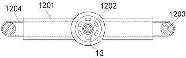
In the figure: 1. a rail bracket; 2. a movable seat; 3. a limiting clamp; 4. a cross frame; 5. electrifying the patch; 6. a conductive support; 7. electrifying the slide bar; 8. a lower bracket; 801. a first rotating base; 802. a first worm; 803. a first chain belt assembly; 804. a first worm gear; 9. a take-up pulley; 10. a cathode connection member; 11. a positioning hook; 12. a motor base; 1201. an internal hollow frame; 1202. a second rotating base; 1203. a second worm; 1204. a second chain belt assembly; 1205. a rotating rod; 1206. a second worm gear; 1207. a hollow outer shell; 1208. a gear shaft; 1209. a third chain belt assembly; 1210. a rack; 1211. a limiting frame; 1212. an elastic member; 1213. an electromagnet; 1214. a limit needle; 13. the motor body.
Detailed Description
The technical solutions in the embodiments of the present invention will be clearly and completely described below with reference to the drawings in the embodiments of the present invention, and it is obvious that the described embodiments are only a part of the embodiments of the present invention, and not all of the embodiments. All other embodiments, which can be derived by a person skilled in the art from the embodiments given herein without making any creative effort, shall fall within the protection scope of the present invention.
Referring to fig. 1-7, the present invention provides a technical solution: a rail type automobile part continuous electrophoresis processing device is used for being installed between a guide rail bracket 1 and a cross frame 4 of a dust-free workshop;
two groups of guide rail brackets 1 are arranged, and the two groups of guide rail brackets 1 are arranged in parallel;
the method comprises the following steps:
the movable seats 2 are distributed in one-to-one correspondence with the guide rail supports 1 and form relative sliding connection with the guide rail supports 1, embedded rolling balls are arranged on the outer walls of the movable seats 2, which are positioned inside the guide rail supports 1, the top of each movable seat 2 is fixedly connected with a limiting clamp 3 for positioning the transverse frame 4, and the transverse frames 4 are installed and positioned by the limiting clamps 3, so that the transverse frames 4 can be conveniently installed and disassembled when needing adjustment and maintenance;
according to the technical scheme shown in fig. 1, an electrifying patch 5 is arranged at the joint of a cross frame 4 and a limiting clamp 3, the outer wall of the bottom of the limiting clamp 3 is electrically connected with a conductive support 6, an electrifying slide bar 7 is fixed on the outer wall of a guide rail support 1 below the limiting clamp 3, the outer wall of the electrifying slide bar 7 is in sliding connection with the outer wall of the lower end of the conductive support 6 in a joint manner, the cross frame 4 and the limiting clamp 3 are electrified in a contact manner under the action of the electrifying patch 5 without causing electric energy loss of required power supply, the electrifying slide bar 7 is embedded and arranged on the outer side wall of the guide rail support 1, the direction of the electrifying slide bar 7 is the same as the whole axis of the guide rail support 1, the outer wall of the joint of the electrifying slide bar 7 and the conductive support 6 is provided with a strip-shaped arc-shaped inner groove, and the electrifying slide bar 7 and the conductive support 6 are in a joint manner, so that when the cross frame 4 and the equipment on the cross frame move in position, energy loss of electric energy supply equipment required on the transverse frame 4 can not occur, and long-term effective energy supply can be maintained;
according to the technical scheme shown in fig. 1 and 7, the lower bracket 8 is fixedly connected to the center of the bottom of the cross frame 4, the bottom of the lower bracket 8 is rotatably provided with a take-up pulley 9, the wire end of the take-up pulley 9 is fixedly connected with a positioning hook 11, a cathode connecting piece 10 is connected between the outer walls of the two ends of the middle shaft of the take-up pulley 9 and the cross frame 4, the cathode connecting piece 10 is electrically connected with an upper wire inner conductor of the take-up pulley 9 and the positioning hook 11, and the position of the positioned automobile part can be conveniently adjusted by using the lower bracket 8 and the upper structure thereof; the lower bracket 8 is designed to be a hollow inverted U-shaped structure, the middle of the joint of the lower bracket 8 and the cross frame 4 is provided with a first rotating seat 801 which is rotatably installed in a penetrating manner, the inner bearings at the two sides of the lower bracket 8 are provided with first worms 802, a first chain belt component 803 is arranged between the first worms 802 and the first rotating seat 801 for protecting the inner installation structure of the lower bracket 8, the rotating kinetic energy of the first rotating seat 801 is effectively utilized under the action of the first chain belt component 803, the first worms 802 are arranged in parallel at the left side and the right side of the cross frame 4, the spiral directions of the first worms 802 at the left side and the right side of the cross frame 4 are the same, the first worms 802 are meshed with the first worm gears 804, the first worm gears 804 are fixed on the outer walls of the middle shafts at the two ends of the take-up pulley 9, and through the mutual meshing between the first worms 802 and the first worm gears 804, the rotation and limiting states of the take-up pulley 9 are changed, the winding and unwinding of the cord on the take-up pulley 9 are realized, the positioning and mounting height adjustment of the automobile parts is achieved, the automobile parts can be effectively placed in the electrolyte, and the cathode state can be provided for the automobile parts during electrophoresis through the action of the cathode connecting piece 10;
according to the technical scheme shown in fig. 1 and fig. 2-4, a motor base 12 is fixedly installed at the center of the top of a cross frame 4, a motor body 13 is fixed between the motor bases 12, the motor body 13 and a cathode connecting piece 10 are electrically connected with an electrified patch 5, a conductive support 6 and an electrified slide bar 7, continuous power supply of electrical equipment on the cross frame 4 is realized, and the motor base 12 is further provided with:
the inner hollow frame 1201 is fixed between the bottoms of the motor bases 12, the middle of the inner hollow frame 1201 is in an annular structure, a middle annular hole of the inner hollow frame 1201 is arranged in a penetrating mode with the lower end of the output shaft of the motor body 13, and the second rotating base 1202 is rotatably arranged in a penetrating mode at the middle annular bottom of the inner hollow frame 1201, so that collision damage of the output shaft with the inner hollow frame 1201 and the second rotating base 1202 when the motor body 13 rotates cannot be caused; a limit frame 1211, two ends of which are connected to the left and right inner parts of the motor base 12 in a penetrating way, and the middle part of the limit frame 1211 is arranged into an annular structure which is penetrated through with the lower end of the output shaft of the motor body 13, and two ends of the limit frame 1211 and the motor base 12 form a penetrating type fit sliding connection; the bottoms of the two ends of the limiting frame 1211 are made of magnetic materials, an elastic piece 1212 is fixed between the tops of the two ends of the limiting frame 1211 and the inside of the motor base 12, an electromagnet 1213 is fixed in the motor base 12 below the bottoms of the two ends of the limiting frame 1211, the electromagnet 1213 is used for generating current control, so that magnetism with different poles is generated, and the positioning installation heights of the limiting frame 1211 and the structure thereon are effectively changed by utilizing the homopolar repulsion and heteropolar attraction effects between the magnetism, so that the limiting frame 1211 and the structure on the limiting frame are close to the second rotating base 1202 or the first rotating base 801, and the two rotating bases can be respectively driven to rotate; the middle annular structure of the limiting frame 1211 and the body of the limiting frame 1211 form a relative rotation structure, the top and the bottom of the annular structure are both connected with limiting needles 1214 in a penetrating manner, the limiting needles 1214 are uniformly arranged at equal intervals, an elastic component is arranged at one end of the limiting needles 1214 positioned in the limiting frame 1211, the middle annular structure of the limiting frame 1211 is vertically and coaxially arranged with the first rotating seat 801 and the second rotating seat 1202, meanwhile, the inner wall of the middle annular structure of the limiting frame 1211 and the cross section of the outer wall of the lower end of the output shaft of the motor body 13 are both arranged into a fitted rectangular structure, the inner wall of the limiting frame 1211 can be vertically fitted and transversely clamped with the outer wall of the output shaft of the motor body 13 before and after the vertical height movement of the limiting frame 1211, and the rotation of the middle annular structure of the limiting frame 1211 is driven by the rotation of the output shaft of the motor body 13;
the first rotating seat 801 and the second rotating seat 1202 are set to be of T-shaped structures which are identical in shape and symmetrically distributed, and the top of the first rotating seat 801 and the bottom of the second rotating seat 1202 are both provided with hollowed-out grooves which are distributed at equal angles, when the limiting frame 1211 and the limiting needle 1214 on the limiting frame 1211 lean against the first rotating seat 801 or the second rotating seat 1202, the limiting needle 1214 can stretch and be guided into the hollowed-out grooves on the first rotating seat 801 and the second rotating seat 1202, so that when the annular structure in the middle of the limiting frame 1211 rotates, the first rotating seat 801 and the second rotating seat 1202 can be driven to rotate, the purposes of subsequent rail-type movement of processing equipment and change of the positioning and mounting height of automobile parts are achieved, and continuous, rapid and effective electrophoretic processing is carried out on the automobile parts;
according to the technical scheme shown in fig. 2-3 and fig. 5, the second worm 1203 is rotatably installed inside the left and right sides of the motor base 12, a second chain belt assembly 1204 is sleeved between the outer wall of the second worm 1203 and the outer wall of the second rotating base 1202, one end of the rotating rod 1205 is rotatably connected to the middle part of the outer wall of the two sides of the motor base 12, a second worm wheel 1206 is sleeved on the rod end of the rotating rod 1205 positioned inside the motor base 12, the rotating motion and the limiting state of the rotating rod 1205 are conveniently adjusted by utilizing the mutual engagement between the second worm 1203 and the second worm wheel 1206, the inner frame 1201 and the outer wall of the two sides of the motor base 12 are vertically fixed and communicated, a gap is reserved between the second chain belt assembly 1204 inside the inner frame 1201 and the inner wall thereof, and the second worm 1203 inside the two sides of the motor base 12 and the outer wall of the second worm wheel 1206 are mutually engaged to control the rotating direction and the limiting state of the rotating rod 1205, the second chain belt assembly 1204 has good transmission effect; the other end of the rotating rod 1205 is rotatably connected into the inner hollow shell 1207, the inner hollow shell 1207 is fixedly penetrated on the cross frame 4, the inner part of the inner hollow shell 1207 is rotatably connected with a gear shaft 1208, and a third chain belt assembly 1209 is sleeved between the outer wall of the middle shaft of the gear shaft 1208 and the outer wall of the rod end of the rotating rod 1205;
according to the technical scheme shown in fig. 1 and 6, the outer wall of the gear shaft 1208 is meshed with the top of the rack 1210, the rack 1210 is fixedly connected to the outer side wall of the guide rail bracket 1, the trend of the rack 1210 is the same as that of the outer side wall of the guide rail bracket 1, the rack 1210 and the guide rail bracket 1 are arranged in a one-to-one correspondence mode, the rotary motion state of the rotating rod 1205 is changed, the gear shaft 1208 is meshed with the rack 1210, the rack 1210 and the guide rail bracket 1 are in a static state, the gear shaft 1208 drives the transverse frame 4 and the upper structure to walk when rotating motion occurs on the gear shaft 1208, the position of the transverse frame 4 is changed, continuous rail type walking of the processing equipment is achieved, and electrophoresis processing is carried out on automobile parts.
The working principle is as follows: when the rail type automobile part continuous electrophoresis processing equipment is used, firstly, the processing equipment is placed through the clamping and positioning of the transverse frame 4 and the limiting clamp 3, when the transverse frame 4 moves under the action of the electrified patch 5, the electrified slide bar 7 and the conductive support 6, the stable energy supply of electric elements on the transverse frame is realized, the positioning height of the limiting frame 1211 and the structure on the limiting frame 1211 is changed through the repulsion or attraction between different magnetism generated by the electromagnet 1213 and the end part of the limiting frame 1211, when the transverse frame moves towards the second rotating seat 1202, the limiting needle 1214 is led into the positioning groove on the second rotating seat 1202, the motor body 13 rotates to drive the annular structure in the middle of the limiting frame 1211 and the second rotating seat 1202 to rotate, under the transmission of the second chain belt component 1204 and the meshing action of the second 1203 worm and the second worm wheel 1206, the motion states of the rotating rod 1205 and the gear shaft 1208 are changed, and the meshing of the gear shaft 1208 and the rack 1210 is utilized, the rail-type movement of the processing equipment is realized, and the electrophoresis processing efficiency is improved;
when the position-limiting frame 1211 moves toward the first rotating base 801, the position-limiting needle 1214 is guided into the positioning groove of the first rotating base 801, so that the wire winding wheel 9 rotates to wind the wire thereon, the positioning height of the positioning hook 11 and the components thereon is changed, the wire is guided into the electrolyte to realize subsequent electrophoresis, and the inner conductor of the wire winding wheel 9 is electrically connected with the cathode connecting piece 10, so that the components guided into the electrolyte maintain the state required by electrophoresis.
Although the present invention has been described in detail with reference to the foregoing embodiments, it will be apparent to those skilled in the art that various changes in the embodiments and/or modifications of the invention can be made, and equivalents and modifications of some features of the invention can be made without departing from the spirit and scope of the invention.
Claims (9)
1. A rail type automobile part continuous electrophoresis processing device is used for being installed between a guide rail bracket and a cross frame of a dust-free workshop;
the guide rail brackets are arranged in two groups, and the two groups of guide rail brackets are arranged in parallel;
it is characterized by comprising:
the moving seats are distributed in one-to-one correspondence with the guide rail brackets and form relative sliding connection with the guide rail brackets, embedded rolling balls are arranged on the outer walls of the moving seats positioned in the guide rail brackets, and limiting clamps for positioning the transverse frames are fixedly connected to the tops of the moving seats;
the power-on patch is arranged at the joint of the transverse frame and the limiting clamp, the outer wall of the bottom of the limiting clamp is electrically connected with the conductive support, the power-on sliding strip is fixed on the outer wall of the guide rail support below the limiting clamp, and meanwhile, the outer wall of the power-on sliding strip is in sliding connection with the outer wall of the lower end of the conductive support in a fit manner;
the lower support is fixedly connected to the center of the bottom of the transverse frame, the bottom of the lower support is rotatably provided with a wire take-up pulley, a wire end of the wire take-up pulley is fixedly connected with a positioning hook, a cathode connecting piece is connected between the outer walls of two ends of a middle shaft of the wire take-up pulley and the transverse frame, and the cathode connecting piece is electrically connected with an inner conductor and the positioning hook on the wire take-up pulley;
and the motor bases are fixedly arranged at the center of the top of the cross frame, motor bodies are fixed between the motor bases, and the motor bodies and the cathode connecting pieces are electrically connected with the electrified patches, the conductive supports and the electrified slide bars.
2. The continuous electrophoretic processing device for the rail type automobile parts as claimed in claim 1, wherein: the electrified sliding strip is embedded on the outer side wall of the guide rail bracket, the trend of the electrified sliding strip is the same as the whole axis of the guide rail bracket, and a strip-shaped arc inner groove is formed in the outer wall of the joint of the electrified sliding strip and the conductive bracket.
3. The continuous electrophoretic processing device for the rail type automobile parts as claimed in claim 1, wherein: the lower support is of an inverted U-shaped structure with a hollow interior, a first rotating seat is arranged in the middle of the joint of the lower support and the cross frame in a penetrating mode, first worms are mounted on bearings inside two sides of the lower support, and a first chain belt assembly is arranged between the first worms and the first rotating seat.
4. The continuous electrophoretic processing device for rail type automobile parts as claimed in claim 3, wherein: the first worms are arranged on the left side and the right side of the cross frame in parallel, the spiral trend directions of the first worms on the left side and the right side of the cross frame are the same, the first worms are meshed with the first worm wheels, and the first worm wheels are fixed on the outer walls of the middle shafts at the two ends of the take-up pulley.
5. The continuous electrophoretic processing device for rail-mounted automobile parts as claimed in claim 1, wherein the motor base is further provided with:
the inner hollow frame is fixed between the bottoms of the motor bases, the middle of the inner hollow frame is of an annular structure, a middle annular hole of the inner hollow frame is arranged in a penetrating mode with the lower end of the output shaft of the motor body, and a second rotating base is rotatably arranged at the middle annular bottom of the inner hollow frame in a penetrating mode;
the second worm rotates and installs inside the left and right sides of motor cabinet, and the cover is equipped with second chain belt subassembly between the outer wall of second worm and the outer wall of second rotation seat to the both sides outer wall middle part of motor cabinet rotates the one end that is connected with the bull stick, and the rod end cover that the bull stick is located the motor cabinet inside in addition is equipped with the second worm wheel.
6. The continuous electrophoretic processing device for rail type automobile parts as claimed in claim 5, wherein: the inner hollow frame and the outer walls of the two sides of the motor base are arranged in a vertically fixed mode, the inner hollow frame is communicated with the outer walls of the two sides of the motor base in a hollow mode, a hole is reserved between the second chain belt component inside the inner hollow frame and the inner wall of the inner hollow frame, and the second worm inside the two sides of the motor base is meshed with the outer wall of the second worm wheel.
7. The continuous electrophoretic processing device for rail type automobile parts as claimed in claim 5, wherein: the other end of the rotating rod is rotatably connected into the hollow outer shell, the hollow outer shell is fixedly penetrated on the cross frame, the inner part of the hollow outer shell is rotatably connected with a gear shaft, and a third chain belt assembly is sleeved between the outer wall of a middle shaft of the gear shaft and the outer wall of the rod end of the rotating rod;
the outer wall of the gear shaft is meshed with the top of the rack, the rack is fixedly connected to the outer side wall of the guide rail support, the direction of the rack is the same as that of the outer side wall of the guide rail support, and the rack and the guide rail support are arranged in a one-to-one correspondence mode.
8. The continuous electrophoretic processing device for rail-mounted automobile parts as claimed in claim 1, wherein the motor base is further provided with:
the two ends of the limiting frame are connected to the inner parts of the left side and the right side of the motor base in a penetrating mode, the middle of the limiting frame is of an annular structure penetrating through the lower end of the output shaft of the motor body, and the two ends of the limiting frame and the motor base are in penetrating type fit sliding connection;
the bottom of the two ends of the limiting frame is made of magnetic materials, an elastic part is fixed between the top of the two ends of the limiting frame and the inside of the motor base, and electromagnets are fixed in the motor base below the bottom of the two ends of the limiting frame.
9. The continuous electrophoretic processing device for rail type automobile parts as claimed in claim 8, wherein: the middle annular structure of the limiting frame and the body of the limiting frame form a relative rotating structure, the top and the bottom of the annular structure are connected with limiting needles in a penetrating manner, the limiting needles are uniformly arranged at equal intervals, an elastic component is arranged at one end of each limiting needle positioned in the limiting frame, the middle annular structure of the limiting frame is vertically and coaxially arranged with the first rotating seat and the second rotating seat, and meanwhile, the cross sections of the inner wall of the middle annular structure of the limiting frame and the outer wall of the lower end of the output shaft of the motor body are both arranged into a fitted rectangular structure;
the first rotating seat and the second rotating seat are arranged to be of T-shaped structures which are the same in shape and symmetrically distributed, and the top of the first rotating seat and the bottom of the second rotating seat are provided with hollowed-out grooves which are distributed at equal angles.
Priority Applications (1)
| Application Number | Priority Date | Filing Date | Title |
|---|---|---|---|
| CN202110995018.XA CN113684518A (en) | 2021-08-27 | 2021-08-27 | Rail mounted automobile parts continuation electrophoresis processing equipment |
Applications Claiming Priority (1)
| Application Number | Priority Date | Filing Date | Title |
|---|---|---|---|
| CN202110995018.XA CN113684518A (en) | 2021-08-27 | 2021-08-27 | Rail mounted automobile parts continuation electrophoresis processing equipment |
Publications (1)
| Publication Number | Publication Date |
|---|---|
| CN113684518A true CN113684518A (en) | 2021-11-23 |
Family
ID=78583398
Family Applications (1)
| Application Number | Title | Priority Date | Filing Date |
|---|---|---|---|
| CN202110995018.XA Withdrawn CN113684518A (en) | 2021-08-27 | 2021-08-27 | Rail mounted automobile parts continuation electrophoresis processing equipment |
Country Status (1)
| Country | Link |
|---|---|
| CN (1) | CN113684518A (en) |
Cited By (1)
| Publication number | Priority date | Publication date | Assignee | Title |
|---|---|---|---|---|
| CN115615374A (en) * | 2022-10-14 | 2023-01-17 | 斯沃博达汽车电子(昆山)有限公司 | A car sensor multi-angle probe height detection equipment |
Citations (12)
| Publication number | Priority date | Publication date | Assignee | Title |
|---|---|---|---|---|
| GB1400698A (en) * | 1974-01-14 | 1975-07-23 | Cheung Wai Manufactory Ltd | Electroplating machine |
| US4243146A (en) * | 1979-04-09 | 1981-01-06 | Production Plus Corporation | Custom changeable hanging rack for finishing system |
| US6197175B1 (en) * | 1998-09-01 | 2001-03-06 | Durr Systems Gmbh | Electrical contacting system for an electrophoretic dip painting plant for motor vehicle bodies |
| JP2008280589A (en) * | 2007-05-11 | 2008-11-20 | Nippon Paint Co Ltd | Electrodeposition painting method |
| US20090250346A1 (en) * | 2006-11-23 | 2009-10-08 | Durr Systems Gmbh | Workpiece carrier for conveying a workpiece to be painted |
| JP2011047009A (en) * | 2009-08-27 | 2011-03-10 | Central Motor Co Ltd | Dipping treatment apparatus |
| CN105483801A (en) * | 2015-12-15 | 2016-04-13 | 芜湖普威技研有限公司 | Electrophoresis tool rack of automobile rear shaft |
| CN108707954A (en) * | 2018-07-21 | 2018-10-26 | 江苏松源机械制造有限公司 | A kind of article hanger of electrophoresis equipment charging and discharging mechanism |
| CN210030925U (en) * | 2019-04-23 | 2020-02-07 | 滁州达世汽车配件有限公司 | Hoisting device for car refueling small door cover plate swimming paint treatment |
| CN111379003A (en) * | 2020-05-15 | 2020-07-07 | 重庆厚泽精密机械有限公司 | A surface quality processing device and process for cathodic electrophoretic paint of auto parts |
| CN112342595A (en) * | 2020-10-27 | 2021-02-09 | 广东美铝科技有限公司 | An aluminum profile gantry type oxidation electrophoresis production line |
| CN212610945U (en) * | 2020-04-30 | 2021-02-26 | 天津新科联泰金属制品有限公司 | High corrosion resistance coating line pretreatment electrophoresis equipment |
-
2021
- 2021-08-27 CN CN202110995018.XA patent/CN113684518A/en not_active Withdrawn
Patent Citations (12)
| Publication number | Priority date | Publication date | Assignee | Title |
|---|---|---|---|---|
| GB1400698A (en) * | 1974-01-14 | 1975-07-23 | Cheung Wai Manufactory Ltd | Electroplating machine |
| US4243146A (en) * | 1979-04-09 | 1981-01-06 | Production Plus Corporation | Custom changeable hanging rack for finishing system |
| US6197175B1 (en) * | 1998-09-01 | 2001-03-06 | Durr Systems Gmbh | Electrical contacting system for an electrophoretic dip painting plant for motor vehicle bodies |
| US20090250346A1 (en) * | 2006-11-23 | 2009-10-08 | Durr Systems Gmbh | Workpiece carrier for conveying a workpiece to be painted |
| JP2008280589A (en) * | 2007-05-11 | 2008-11-20 | Nippon Paint Co Ltd | Electrodeposition painting method |
| JP2011047009A (en) * | 2009-08-27 | 2011-03-10 | Central Motor Co Ltd | Dipping treatment apparatus |
| CN105483801A (en) * | 2015-12-15 | 2016-04-13 | 芜湖普威技研有限公司 | Electrophoresis tool rack of automobile rear shaft |
| CN108707954A (en) * | 2018-07-21 | 2018-10-26 | 江苏松源机械制造有限公司 | A kind of article hanger of electrophoresis equipment charging and discharging mechanism |
| CN210030925U (en) * | 2019-04-23 | 2020-02-07 | 滁州达世汽车配件有限公司 | Hoisting device for car refueling small door cover plate swimming paint treatment |
| CN212610945U (en) * | 2020-04-30 | 2021-02-26 | 天津新科联泰金属制品有限公司 | High corrosion resistance coating line pretreatment electrophoresis equipment |
| CN111379003A (en) * | 2020-05-15 | 2020-07-07 | 重庆厚泽精密机械有限公司 | A surface quality processing device and process for cathodic electrophoretic paint of auto parts |
| CN112342595A (en) * | 2020-10-27 | 2021-02-09 | 广东美铝科技有限公司 | An aluminum profile gantry type oxidation electrophoresis production line |
Cited By (1)
| Publication number | Priority date | Publication date | Assignee | Title |
|---|---|---|---|---|
| CN115615374A (en) * | 2022-10-14 | 2023-01-17 | 斯沃博达汽车电子(昆山)有限公司 | A car sensor multi-angle probe height detection equipment |
Similar Documents
| Publication | Publication Date | Title |
|---|---|---|
| CN217350267U (en) | Cable traction device for construction based on electric power engineering | |
| CN112572495A (en) | Running gear of robot is patrolled and examined to track | |
| CN114779123A (en) | High tension transmission line leakage detector | |
| CN118928575A (en) | Magnetic adsorption wall-climbing robot with controllable adsorption force | |
| CN208196186U (en) | A kind of auxiliary support apparatus with clamping function | |
| CN110919566A (en) | Angle-adjustable clamp for bearing of railway wagon | |
| CN107030708B (en) | Material clamping manipulator moving device | |
| CN117578317A (en) | High-strength protection device for high-voltage power | |
| CN209793713U (en) | Factory's assembly line is with snatching formula robotic arm | |
| CN214295653U (en) | Electric vehicle battery replacing system | |
| CN212412505U (en) | A sealed insulated switchgear | |
| CN220209560U (en) | A conductive device for electrostatic adsorption belts | |
| CN116246838A (en) | Automobile wire harness rubber coating device | |
| CN108225280A (en) | Modular light source support for machine vision | |
| CN209977166U (en) | Movement mechanism | |
| CN219535971U (en) | Angle-adjustable solar photovoltaic panel | |
| CN209766816U (en) | Mobile electricity taking equipment | |
| CN208181253U (en) | A kind of comprehensive twin-differential vision guided navigation intelligence AGV body construction | |
| CN109347245A (en) | A kind of fire-proof motor protective device | |
| KR200429751Y1 (en) | Power supply of mobile device powered by electricity | |
| CN113276975A (en) | Controllable permanent magnetism athey wheel of magnetic force and have its robot | |
| CN221485494U (en) | Effectual resistance test anchor clamps of centre gripping | |
| CN217551629U (en) | Sheet metal welding processing device | |
| CN110112626A (en) | Movable type takes electric equipment | |
| CN207516453U (en) | A kind of L-type aging unwheeling of automatic power |
Legal Events
| Date | Code | Title | Description |
|---|---|---|---|
| PB01 | Publication | ||
| PB01 | Publication | ||
| SE01 | Entry into force of request for substantive examination | ||
| SE01 | Entry into force of request for substantive examination | ||
| WW01 | Invention patent application withdrawn after publication |
Application publication date: 20211123 |
|
| WW01 | Invention patent application withdrawn after publication |