CN113684464B - Winding type equipment for preparing graphene composite film - Google Patents
Winding type equipment for preparing graphene composite film Download PDFInfo
- Publication number
- CN113684464B CN113684464B CN202110992659.XA CN202110992659A CN113684464B CN 113684464 B CN113684464 B CN 113684464B CN 202110992659 A CN202110992659 A CN 202110992659A CN 113684464 B CN113684464 B CN 113684464B
- Authority
- CN
- China
- Prior art keywords
- roller
- film
- graphene composite
- absorption
- film layer
- Prior art date
- Legal status (The legal status is an assumption and is not a legal conclusion. Google has not performed a legal analysis and makes no representation as to the accuracy of the status listed.)
- Active
Links
Images


Classifications
-
- C—CHEMISTRY; METALLURGY
- C23—COATING METALLIC MATERIAL; COATING MATERIAL WITH METALLIC MATERIAL; CHEMICAL SURFACE TREATMENT; DIFFUSION TREATMENT OF METALLIC MATERIAL; COATING BY VACUUM EVAPORATION, BY SPUTTERING, BY ION IMPLANTATION OR BY CHEMICAL VAPOUR DEPOSITION, IN GENERAL; INHIBITING CORROSION OF METALLIC MATERIAL OR INCRUSTATION IN GENERAL
- C23C—COATING METALLIC MATERIAL; COATING MATERIAL WITH METALLIC MATERIAL; SURFACE TREATMENT OF METALLIC MATERIAL BY DIFFUSION INTO THE SURFACE, BY CHEMICAL CONVERSION OR SUBSTITUTION; COATING BY VACUUM EVAPORATION, BY SPUTTERING, BY ION IMPLANTATION OR BY CHEMICAL VAPOUR DEPOSITION, IN GENERAL
- C23C14/00—Coating by vacuum evaporation, by sputtering or by ion implantation of the coating forming material
- C23C14/22—Coating by vacuum evaporation, by sputtering or by ion implantation of the coating forming material characterised by the process of coating
- C23C14/56—Apparatus specially adapted for continuous coating; Arrangements for maintaining the vacuum, e.g. vacuum locks
-
- C—CHEMISTRY; METALLURGY
- C23—COATING METALLIC MATERIAL; COATING MATERIAL WITH METALLIC MATERIAL; CHEMICAL SURFACE TREATMENT; DIFFUSION TREATMENT OF METALLIC MATERIAL; COATING BY VACUUM EVAPORATION, BY SPUTTERING, BY ION IMPLANTATION OR BY CHEMICAL VAPOUR DEPOSITION, IN GENERAL; INHIBITING CORROSION OF METALLIC MATERIAL OR INCRUSTATION IN GENERAL
- C23C—COATING METALLIC MATERIAL; COATING MATERIAL WITH METALLIC MATERIAL; SURFACE TREATMENT OF METALLIC MATERIAL BY DIFFUSION INTO THE SURFACE, BY CHEMICAL CONVERSION OR SUBSTITUTION; COATING BY VACUUM EVAPORATION, BY SPUTTERING, BY ION IMPLANTATION OR BY CHEMICAL VAPOUR DEPOSITION, IN GENERAL
- C23C14/00—Coating by vacuum evaporation, by sputtering or by ion implantation of the coating forming material
- C23C14/06—Coating by vacuum evaporation, by sputtering or by ion implantation of the coating forming material characterised by the coating material
- C23C14/0605—Carbon
-
- C—CHEMISTRY; METALLURGY
- C23—COATING METALLIC MATERIAL; COATING MATERIAL WITH METALLIC MATERIAL; CHEMICAL SURFACE TREATMENT; DIFFUSION TREATMENT OF METALLIC MATERIAL; COATING BY VACUUM EVAPORATION, BY SPUTTERING, BY ION IMPLANTATION OR BY CHEMICAL VAPOUR DEPOSITION, IN GENERAL; INHIBITING CORROSION OF METALLIC MATERIAL OR INCRUSTATION IN GENERAL
- C23C—COATING METALLIC MATERIAL; COATING MATERIAL WITH METALLIC MATERIAL; SURFACE TREATMENT OF METALLIC MATERIAL BY DIFFUSION INTO THE SURFACE, BY CHEMICAL CONVERSION OR SUBSTITUTION; COATING BY VACUUM EVAPORATION, BY SPUTTERING, BY ION IMPLANTATION OR BY CHEMICAL VAPOUR DEPOSITION, IN GENERAL
- C23C14/00—Coating by vacuum evaporation, by sputtering or by ion implantation of the coating forming material
- C23C14/22—Coating by vacuum evaporation, by sputtering or by ion implantation of the coating forming material characterised by the process of coating
- C23C14/24—Vacuum evaporation
-
- C—CHEMISTRY; METALLURGY
- C23—COATING METALLIC MATERIAL; COATING MATERIAL WITH METALLIC MATERIAL; CHEMICAL SURFACE TREATMENT; DIFFUSION TREATMENT OF METALLIC MATERIAL; COATING BY VACUUM EVAPORATION, BY SPUTTERING, BY ION IMPLANTATION OR BY CHEMICAL VAPOUR DEPOSITION, IN GENERAL; INHIBITING CORROSION OF METALLIC MATERIAL OR INCRUSTATION IN GENERAL
- C23C—COATING METALLIC MATERIAL; COATING MATERIAL WITH METALLIC MATERIAL; SURFACE TREATMENT OF METALLIC MATERIAL BY DIFFUSION INTO THE SURFACE, BY CHEMICAL CONVERSION OR SUBSTITUTION; COATING BY VACUUM EVAPORATION, BY SPUTTERING, BY ION IMPLANTATION OR BY CHEMICAL VAPOUR DEPOSITION, IN GENERAL
- C23C14/00—Coating by vacuum evaporation, by sputtering or by ion implantation of the coating forming material
- C23C14/22—Coating by vacuum evaporation, by sputtering or by ion implantation of the coating forming material characterised by the process of coating
- C23C14/54—Controlling or regulating the coating process
- C23C14/542—Controlling the film thickness or evaporation rate
- C23C14/545—Controlling the film thickness or evaporation rate using measurement on deposited material
-
- C—CHEMISTRY; METALLURGY
- C23—COATING METALLIC MATERIAL; COATING MATERIAL WITH METALLIC MATERIAL; CHEMICAL SURFACE TREATMENT; DIFFUSION TREATMENT OF METALLIC MATERIAL; COATING BY VACUUM EVAPORATION, BY SPUTTERING, BY ION IMPLANTATION OR BY CHEMICAL VAPOUR DEPOSITION, IN GENERAL; INHIBITING CORROSION OF METALLIC MATERIAL OR INCRUSTATION IN GENERAL
- C23C—COATING METALLIC MATERIAL; COATING MATERIAL WITH METALLIC MATERIAL; SURFACE TREATMENT OF METALLIC MATERIAL BY DIFFUSION INTO THE SURFACE, BY CHEMICAL CONVERSION OR SUBSTITUTION; COATING BY VACUUM EVAPORATION, BY SPUTTERING, BY ION IMPLANTATION OR BY CHEMICAL VAPOUR DEPOSITION, IN GENERAL
- C23C14/00—Coating by vacuum evaporation, by sputtering or by ion implantation of the coating forming material
- C23C14/22—Coating by vacuum evaporation, by sputtering or by ion implantation of the coating forming material characterised by the process of coating
- C23C14/56—Apparatus specially adapted for continuous coating; Arrangements for maintaining the vacuum, e.g. vacuum locks
- C23C14/564—Means for minimising impurities in the coating chamber such as dust, moisture, residual gases
-
- C—CHEMISTRY; METALLURGY
- C23—COATING METALLIC MATERIAL; COATING MATERIAL WITH METALLIC MATERIAL; CHEMICAL SURFACE TREATMENT; DIFFUSION TREATMENT OF METALLIC MATERIAL; COATING BY VACUUM EVAPORATION, BY SPUTTERING, BY ION IMPLANTATION OR BY CHEMICAL VAPOUR DEPOSITION, IN GENERAL; INHIBITING CORROSION OF METALLIC MATERIAL OR INCRUSTATION IN GENERAL
- C23C—COATING METALLIC MATERIAL; COATING MATERIAL WITH METALLIC MATERIAL; SURFACE TREATMENT OF METALLIC MATERIAL BY DIFFUSION INTO THE SURFACE, BY CHEMICAL CONVERSION OR SUBSTITUTION; COATING BY VACUUM EVAPORATION, BY SPUTTERING, BY ION IMPLANTATION OR BY CHEMICAL VAPOUR DEPOSITION, IN GENERAL
- C23C14/00—Coating by vacuum evaporation, by sputtering or by ion implantation of the coating forming material
- C23C14/58—After-treatment
Landscapes
- Chemical & Material Sciences (AREA)
- Chemical Kinetics & Catalysis (AREA)
- Engineering & Computer Science (AREA)
- Materials Engineering (AREA)
- Mechanical Engineering (AREA)
- Metallurgy (AREA)
- Organic Chemistry (AREA)
- Carbon And Carbon Compounds (AREA)
Abstract
本发明公开一种用于石墨烯复合薄膜制备的卷绕式设备,主要包括腔室、蒸发模块、涂覆模块和图案生成辊;蒸发模块通过真空蒸发镀膜在柔性基膜表面沉积催化剂膜层。涂覆模块将石墨烯复合材料涂覆在催化剂膜层之上形成涂覆层;涂覆层在涂覆层之下的催化剂的作用下催化生长成石墨烯复合湿膜层。图案生成辊通过负压吸收对绕经图案生成辊的柔性基膜上尚未成型的湿膜层进行部分去除,从而在柔性基膜上形成具有特定图案的石墨烯复合薄膜。图案生成辊包括内辊和外辊;外辊布置有网孔阵列;内辊布置有吸收孔阵列,吸收孔与网孔之间通过吸收管道相连;内辊内部为空腔结构,内辊的端部与低真空泵相连,低真空泵将内辊内部抽成相对于腔室内气压的负压。

The invention discloses a winding device for preparing graphene composite films, which mainly includes a chamber, an evaporation module, a coating module and a pattern generating roller; the evaporation module deposits a catalyst film layer on the surface of a flexible base film through vacuum evaporation coating. The coating module coats the graphene composite material on the catalyst film layer to form a coating layer; the coating layer catalyzes and grows into a graphene composite wet film layer under the action of the catalyst under the coating layer. The pattern generation roller partially removes the unformed wet film layer on the flexible base film passing through the pattern generation roller through negative pressure absorption, thereby forming a graphene composite film with a specific pattern on the flexible base film. The pattern generating roller includes an inner roller and an outer roller; the outer roller is arranged with a mesh array; the inner roller is arranged with an array of absorption holes, and the absorption holes and the mesh are connected through an absorption pipe; the inner roller is a cavity structure, and the end of the inner roller The part is connected with the low vacuum pump, and the low vacuum pump pumps the interior of the inner roller into a negative pressure relative to the air pressure in the chamber.
Description
技术领域technical field
本发明属于石墨烯复合薄膜制备技术领域,特别涉及一种用于石墨烯复合薄膜制备的卷绕式设备。The invention belongs to the technical field of graphene composite film preparation, and in particular relates to a winding device for preparing graphene composite film.
背景技术Background technique
石墨烯作为新型纳米材料,比传统材料具有更高的比表面积、强度、导热和导电性能。目前,在现有材料里添加石墨烯制成石墨烯复合材料以改善原材料的性能成为当前研究和应用的热点。在众多石墨烯复合材料中,石墨烯-硅橡胶复合材料具有优异的力学、热学以及电学性能,在航空航天领域具有良好的应用前景。硅橡胶是以Si-O-Si键为主链,以有机基团为侧链的兼有无机和有机性质的弹性聚合物,由于分子链相互作用力弱,难以产生自由移动的电子,且在高温下会发生老化分解,硅橡胶强度较低,几乎不导电,未经补强的硅橡胶抗拉强度仅为0.3MPa,普通硅橡胶材料只能在260℃内安全使用,应用价值有限。为了克服硅橡胶在强度、导电性能上的缺陷,进一步提高耐高温性能,众多科研人员将多种石墨烯掺杂到其中,提高硅橡胶的强度、耐热性以及导电性,以满足空间探索对硅橡胶材料性能的苛刻要求。As a new nanomaterial, graphene has higher specific surface area, strength, thermal conductivity and electrical conductivity than traditional materials. At present, adding graphene to existing materials to make graphene composite materials to improve the performance of raw materials has become a hot spot in current research and application. Among many graphene composite materials, graphene-silicone rubber composite materials have excellent mechanical, thermal and electrical properties, and have good application prospects in the aerospace field. Silicone rubber is an elastic polymer with both inorganic and organic properties with Si-O-Si bonds as the main chain and organic groups as side chains. Due to the weak molecular chain interaction, it is difficult to generate freely moving electrons, and in Aging and decomposition will occur at high temperature. The strength of silicone rubber is low and it is almost non-conductive. The tensile strength of unreinforced silicone rubber is only 0.3MPa. Ordinary silicone rubber materials can only be used safely within 260°C, and their application value is limited. In order to overcome the shortcomings of silicone rubber in terms of strength and electrical conductivity, and further improve high-temperature resistance, many researchers have doped a variety of graphene into it to improve the strength, heat resistance, and electrical conductivity of silicone rubber to meet the needs of space exploration. Strict requirements for the performance of silicone rubber materials.
但目前的石墨烯-硅橡胶复合材料的制备工艺比较复杂,还多停留在实验室阶段,难以实现产业化。特别是近期提出的石墨烯-硅橡胶复合柔性薄膜材料,以其轻薄、柔韧及形状多变等特点可以在更多领域获得更广泛的应用,但由于其产业化技术尚属空白,限制了该材料的推广应用。However, the current preparation process of graphene-silicone rubber composite materials is relatively complicated, and most of them remain in the laboratory stage, making it difficult to realize industrialization. In particular, the recently proposed graphene-silicone rubber composite flexible film material can be widely used in more fields due to its lightness, flexibility, and changeable shape. Promotion and application of materials.
发明内容Contents of the invention
本发明提出一种卷对卷式的石墨烯复合薄膜制备设备,满足以柔性石墨烯-硅橡胶复合薄膜为代表柔性石墨烯复合薄膜材料大规模生产设备及技术需求。The invention proposes a roll-to-roll type graphene composite film preparation equipment, which meets the large-scale production equipment and technical requirements of flexible graphene-silicon rubber composite film materials represented by flexible graphene composite film.
本发明提供一种用于石墨烯复合薄膜制备的卷绕式设备,主要包括腔室、蒸发模块、涂覆模块、定型模块和卷绕系统;卷绕系统包括放卷辊、收卷辊、蒸发主辊和图案生成辊;在腔室内通过隔板分隔为蒸发工作区和非蒸发工作区,蒸发模块设置在蒸发工作区内;图案生成辊布置在涂覆模块和定型模块之间;图案生成辊通过负压吸收对绕经图案生成辊的柔性基膜上尚未成型的湿膜层进行部分去除,从而在柔性基膜上形成具有特定图案的石墨烯复合薄膜。The invention provides a winding-type equipment for the preparation of graphene composite films, which mainly includes a chamber, an evaporation module, a coating module, a shaping module and a winding system; the winding system includes an unwinding roller, a winding roller, an evaporation The main roller and the pattern generating roller; the chamber is divided into an evaporation working area and a non-evaporating working area by a partition, and the evaporation module is set in the evaporation working area; the pattern generating roller is arranged between the coating module and the sizing module; the pattern generating roller Partially remove the unformed wet film layer on the flexible base film wound around the pattern generating roller by negative pressure absorption, so as to form a graphene composite film with a specific pattern on the flexible base film.
腔室上设置有真空系统和充气系统;真空系统用于在腔室内创造清洁的真空环境,充气系统用于充入工作气体。在石墨烯复合薄膜制备前,先通过真空系统将腔室内的气体抽除,使腔室内的真空度达到10Pa以上(即压力达到10Pa以下),然后通过充气系统向腔室内的非蒸发工作区通入制备石墨烯复合薄膜所需的工作气体,控制腔室内的非蒸发工作区的气体压力在0.01MPa~0.1MPa范围内。蒸发主辊跨跃蒸发工作区和非蒸发工作区布置,隔板与蒸发主辊辊面的间隙在1-5mm范围内。腔室上还设置有用于测量环境参数的压力表、湿度表及温度表。The chamber is provided with a vacuum system and an inflation system; the vacuum system is used to create a clean vacuum environment in the chamber, and the inflation system is used to charge the working gas. Before the graphene composite film is prepared, the gas in the chamber is first pumped out through the vacuum system, so that the vacuum degree in the chamber reaches above 10Pa (that is, the pressure reaches below 10Pa), and then the non-evaporative working area in the chamber is ventilated through the inflation system. Inject the working gas required for preparing the graphene composite film, and control the gas pressure in the non-evaporative working area in the chamber within the range of 0.01MPa~0.1MPa. The evaporating main roller is arranged across the evaporating working area and the non-evaporating working area, and the gap between the separator and the surface of the evaporating main roller is in the range of 1-5mm. The chamber is also provided with pressure gauges, hygrometers and temperature gauges for measuring environmental parameters.
蒸发主辊位于放卷辊的下游和涂覆模块的上游;蒸发模块位于蒸发主辊的下方,用于通过真空蒸发镀膜在柔性基膜表面沉积催化剂膜层。The evaporation main roll is located downstream of the unwinding roll and upstream of the coating module; the evaporation module is located below the evaporation main roll, and is used to deposit a catalyst film layer on the surface of the flexible base film by vacuum evaporation coating.
图案生成辊设置在涂覆模块的下游。图案生成辊为双层机构,包括内辊和外辊;外辊辊面为网状结构,上面布置有网孔阵列;内辊的辊壁上布置有吸收孔阵列,吸收孔阵列中的吸收孔与网孔阵列中的网孔之间通过吸收管道相连,吸收孔和网孔之间一一对应;内辊内部为空腔结构,内辊的端部与低真空泵相连,低真空泵将内辊内部抽成相对于腔室内气压的负压。A pattern generating roller is arranged downstream of the coating module. The pattern generating roller is a double-layer mechanism, including an inner roller and an outer roller; the roller surface of the outer roller is a mesh structure with a mesh array arranged on it; the roller wall of the inner roller is arranged with an array of absorption holes, and the absorption holes in the array of absorption holes The meshes in the mesh array are connected by absorption pipes, and the absorption holes correspond to the meshes one by one; the inside of the inner roller is a cavity structure, and the end of the inner roller is connected with a low-vacuum pump, and the low-vacuum pump pumps the inner roller Pump down to a negative pressure relative to the air pressure in the chamber.
内辊的辊壁内侧设置有遮掩筒插槽;遮掩筒插槽内可插入遮掩筒,遮掩筒的展开形状与要在柔性基膜上形成的石墨烯复合薄膜具有的特定图案相对应;遮掩筒从内辊辊壁内侧对辊壁上的吸收孔阵列中某些吸收孔进行遮挡密封;图案生成辊工作时,内辊持续稳定的负压会从那些未被遮挡的吸收孔经由与之相连的吸收管道和网孔对覆盖在这些网孔上的湿膜层产生负压吸收,从而对绕经图案生成辊的柔性基膜上的这部分湿膜层进行去除。The inner side of the roller wall of the inner roller is provided with a masking tube slot; a masking tube can be inserted into the masking tube slot, and the unfolded shape of the masking tube corresponds to the specific pattern of the graphene composite film to be formed on the flexible base film; the masking tube Cover and seal some of the absorbing holes in the array of absorbing holes on the roller wall from the inner side of the inner roller wall; when the pattern generating roller is working, the continuous and stable negative pressure of the inner roller will pass through the unblocked absorbing holes through the connected The suction ducts and meshes create negative pressure suction on the wet film layer overlying these mesh holes, thereby removing this portion of the wet film layer on the flexible base film wound around the pattern forming roller.
通过控制低真空泵的排气速度,可以调节图案生成辊对湿膜层的负压吸收力度,对覆盖在网孔上的这部分湿膜层进行完全去除或部分去除。By controlling the exhaust speed of the low vacuum pump, the negative pressure absorption strength of the pattern forming roller to the wet film layer can be adjusted, and the part of the wet film layer covering the mesh can be completely or partially removed.
在一种实施方案中,图案生成辊还包括控制器;在吸收管道上设置有电控阀门;控制器接收到图案生成指令后,根据预设的图案生成程序开启某些吸收管道上的电控阀门,内辊的负压会从这些吸收管道经由与之相连的吸收孔和网孔对覆盖在这些网孔上的湿膜层产生负压吸收,从而对绕经图案生成辊的柔性基膜上的这部分湿膜层进行去除。控制器可单独对某些吸收管道上的电控阀门开度进行调节,来单独控制与这些吸收管道相连的受控网孔对湿膜层的负压吸收力度,从而对覆盖在受控网孔上的湿膜层进行完全去除或部分去除。控制器通过分别控制多个相邻网孔对湿膜层的负压吸收力度,使这些相邻网孔的负压吸收力度之间形成渐变的趋势,从而使覆盖在这些相邻网孔上的湿膜层形成深度连续渐变的沟槽图案。另外,控制器通过分别控制多个区域的网孔对湿膜层的负压吸收力度,还可以在湿膜层的多个区域上形成深浅各异的图案。In one embodiment, the pattern generating roller also includes a controller; an electric control valve is arranged on the absorption pipeline; after the controller receives the pattern generation instruction, it turns on the electric control valves on some absorption pipelines according to the preset pattern generation program. Valves, the negative pressure of the inner roller will generate negative pressure absorption from these absorption pipes through the absorption holes and meshes connected to them to the wet film layer covered on these meshes, so as to flow on the flexible base film of the pattern generation roller This part of the wet film layer is removed. The controller can individually adjust the opening of the electronically controlled valves on some absorption pipes to individually control the negative pressure absorption of the wet film layer by the controlled meshes connected to these absorption pipes, so as to control the negative pressure absorbed by the controlled meshes. The wet film layer on the surface is completely or partially removed. The controller controls the negative pressure absorption strength of the wet film layer by a plurality of adjacent meshes respectively, so that the negative pressure absorption strength of these adjacent meshes forms a gradual trend, so that the covering on these adjacent meshes The wet film layer forms a groove pattern with a continuous gradient of depth. In addition, the controller can also form patterns with different depths on multiple areas of the wet film layer by separately controlling the negative pressure absorption strength of the meshes in multiple areas on the wet film layer.
涂覆模块将石墨烯复合材料涂覆在柔性基膜表面的催化剂膜层之上,形成涂覆层;在涂覆模块下游设置有生长辊;柔性基膜绕经生长辊时,涂覆层在涂覆层之下的催化剂的作用下催化生长成石墨烯复合湿膜层。The coating module coats the graphene composite material on the catalyst film layer on the surface of the flexible base film to form a coating layer; a growth roll is arranged downstream of the coating module; when the flexible base film winds around the growth roll, the coating layer Under the action of the catalyst under the coating layer, the graphene composite wet film layer is catalyzed and grown.
在图案生成辊和定型模块之间设置有膜厚监测装置,膜厚监测装置对湿膜层进行在线膜厚监测;涂覆模块根据接收到的膜厚监测信号对石墨烯复合材料的供给量进行动态反馈控制,从而在线调节石墨烯复合薄膜的膜厚。A film thickness monitoring device is arranged between the pattern generating roller and the sizing module, and the film thickness monitoring device performs online film thickness monitoring on the wet film layer; the coating module monitors the supply of the graphene composite material according to the received film thickness monitoring signal Dynamic feedback control to adjust the film thickness of the graphene composite film online.
涂覆模块包括布置在柔性基膜幅宽方向上的多个涂覆单元;膜厚监测装置在柔性基膜幅宽方向上对湿膜层进行多点在线膜厚监测;涂覆单元会根据与该涂覆单元对应区域上的膜厚监测信号进行动态反馈控制,在线调节该区域上的石墨烯复合薄膜膜厚。The coating module includes a plurality of coating units arranged in the width direction of the flexible base film; the film thickness monitoring device performs multi-point online film thickness monitoring on the wet film layer in the width direction of the flexible base film; The coating unit performs dynamic feedback control on the film thickness monitoring signal on the corresponding area, and online adjusts the film thickness of the graphene composite film on the area.
定型模块位于图案生成辊的下游;定型模块采用光照加热或烘干箱加热,对湿膜层进行干燥定型,使湿膜层形成石墨烯复合薄膜。定型模块的加热温度区间为100℃~150℃。在定型模块的下游设置有冷却辊,冷却辊对经过加热定型后的石墨烯复合薄膜进行降温冷却。The sizing module is located downstream of the pattern generating roller; the sizing module uses light heating or oven heating to dry and shape the wet film layer, so that the wet film layer forms a graphene composite film. The heating temperature range of the shaping module is 100°C~150°C. A cooling roll is arranged downstream of the shaping module, and the cooling roll cools down the heated and shaped graphene composite film.
在蒸发主辊的下游布置有控温辊;控温辊的控温区间为40 ~ 100℃;控温辊将绕经控温辊的柔性基膜的温度调节至催化反应温度范围内。A temperature control roller is arranged downstream of the evaporation main roller; the temperature control range of the temperature control roller is 40 ~ 100°C; the temperature control roller adjusts the temperature of the flexible base film wrapped around the temperature control roller to within the catalytic reaction temperature range.
定型模块下游设置有层压辊,层压辊为2个,相对布置;腔室内设置有保护膜卷辊。层压辊用于将来自保护膜卷辊的保护膜压制覆盖在定型后的石墨烯复合薄膜表面,对柔性基膜上的石墨烯复合薄膜表面进行保护,防止石墨烯复合薄膜在收卷和运输过程中受到损伤;保护膜优选热剥离胶带。在层压辊的上游和下游均设置有去静电装置。优选地,层压辊上设置有用于测量层压辊之间对压压力的压力传感器和压力控制器,通过压力传感器反馈,能够实时监控和调节层压辊之间的对压压力,保证保护膜压制在石墨烯复合薄膜表面的同时不会损伤薄膜。Lamination rollers are arranged downstream of the shaping module, and there are two lamination rollers arranged opposite to each other; protective film rolls are arranged in the chamber. The lamination roller is used to press the protective film from the protective film roll to cover the surface of the shaped graphene composite film, protect the surface of the graphene composite film on the flexible base film, and prevent the graphene composite film from being rolled and transported. Damaged during the process; protective film is preferably heat release tape. Both upstream and downstream of the lamination rollers are provided with destaticizing devices. Preferably, the lamination rollers are provided with a pressure sensor and a pressure controller for measuring the pressing pressure between the laminating rollers. Through the feedback of the pressure sensor, the pressing pressure between the laminating rollers can be monitored and adjusted in real time to ensure that the protective film It will not damage the film while pressing on the surface of the graphene composite film.
本发明的用于石墨烯复合薄膜制备的卷绕式设备的工作过程主要包括:The working process of the roll-up equipment for the preparation of graphene composite film of the present invention mainly comprises:
(1)启动蒸发模块进行真空蒸发镀膜,在绕经蒸发主辊的柔性基膜表面沉积催化剂膜层;启动蒸发模块下游的涂覆模块,涂覆模块将石墨烯复合材料涂覆在柔性基膜表面的催化剂膜层之上,形成涂覆层;在涂覆模块下游设置有生长辊;柔性基膜绕经生长辊时,涂覆层在涂覆层之下的催化剂的作用下催化生长成石墨烯复合湿膜层;(1) Start the evaporation module for vacuum evaporation coating, and deposit a catalyst film layer on the surface of the flexible base film that passes through the evaporation main roller; start the coating module downstream of the evaporation module, and the coating module coats the graphene composite material on the flexible base film On the catalyst film layer on the surface, a coating layer is formed; a growth roll is arranged downstream of the coating module; when the flexible base film passes through the growth roll, the coating layer is catalyzed and grown into graphite under the action of the catalyst under the coating layer vinyl composite wet film layer;
(2)设置在生长辊下游的图案生成辊通过负压吸收过程对绕经辊体的柔性基膜上尚未成型的湿膜层进行部分去除,使湿膜层产生设定的图案;(2) The pattern forming roller arranged downstream of the growing roller partially removes the unformed wet film layer on the flexible base film wound around the roller body through a negative pressure absorption process, so that the wet film layer produces a set pattern;
(3)通过设置在图案生成辊下游的定型模块对湿膜层进行加热干燥定型,使湿膜层形成石墨烯复合薄膜;定型模块采用光照加热或烘干箱加热;形成的石墨烯复合薄膜具有特定的图案。(3) The wet film layer is heated, dried and shaped through the shaping module arranged downstream of the pattern generating roller, so that the wet film layer forms a graphene composite film; the shaping module is heated by light or a drying oven; the formed graphene composite film has specific patterns.
在启动蒸发模块之前,要通过真空系统对腔室进行抽真空,当腔室内的真空度达到设定值时,通过充气系统向非蒸发工作区充入工作气体,并控制非蒸发工作区的气体压力在0.01MPa~0.1MPa范围内。Before starting the evaporation module, the chamber should be evacuated through the vacuum system. When the vacuum degree in the chamber reaches the set value, the working gas will be filled into the non-evaporative working area through the inflation system, and the gas in the non-evaporative working area will be controlled. The pressure is in the range of 0.01MPa~0.1MPa.
在图案生成辊的下游还设置有膜厚监测装置,膜厚监测装置对湿膜层进行在线膜厚监测;涂覆模块根据接收到的膜厚监测信号对石墨烯复合材料的供给量进行动态反馈控制,从而在线调节石墨烯复合薄膜的膜厚。膜厚监测装置在柔性基膜幅宽方向上对湿膜层进行多点在线膜厚监测;涂覆单元会根据与该涂覆单元对应区域上的膜厚监测信号进行动态反馈控制,在线调节该区域上的石墨烯复合薄膜膜厚。A film thickness monitoring device is also installed downstream of the pattern generating roller, and the film thickness monitoring device performs online film thickness monitoring on the wet film layer; the coating module dynamically feeds back the supply of the graphene composite material according to the received film thickness monitoring signal Control, so as to adjust the film thickness of the graphene composite film online. The film thickness monitoring device performs multi-point online film thickness monitoring on the wet film layer in the width direction of the flexible base film; the coating unit will perform dynamic feedback control according to the film thickness monitoring signal on the area corresponding to the coating unit, and adjust the film thickness online. The film thickness of the graphene composite thin film on the region.
本发明的有益效果:Beneficial effects of the present invention:
本发明的卷绕式设备通过对密闭腔室抽真空再充入工作气体内为石墨烯复合薄膜的制备提供清洁环境。通过真空蒸发镀膜先在柔性基底上沉积石墨烯复合材料生长所需的催化剂层,使涂覆其上的石墨烯复合材料生长成湿膜层,再通过图案生成辊的负压吸收过程使湿膜层产生设定的图案,并通过定型模块对湿膜层进行加热干燥定型,最终获得具有特定图案的石墨烯复合柔性薄膜。该设备可以实现以石墨烯-硅橡胶复合薄膜为代表的石墨烯复合柔性薄膜的大规模批量生产。该柔性薄膜优异的耐热性、高强度、优秀的电磁屏蔽特性,以及其具有的特定的图案,使该产品可以满足某些特殊场合的应用。The winding device of the present invention provides a clean environment for the preparation of the graphene composite film by vacuumizing the sealed chamber and filling it with working gas. The catalyst layer required for the growth of the graphene composite material is first deposited on the flexible substrate by vacuum evaporation coating, so that the graphene composite material coated on it grows into a wet film layer, and then the wet film is made by the negative pressure absorption process of the pattern forming roller. The layer generates a set pattern, and the wet film layer is heated, dried and shaped by the shaping module, and finally a graphene composite flexible film with a specific pattern is obtained. The equipment can realize large-scale mass production of graphene composite flexible films represented by graphene-silicone rubber composite films. The flexible film has excellent heat resistance, high strength, excellent electromagnetic shielding properties, and its specific pattern, so that the product can meet the application of some special occasions.
附图说明Description of drawings
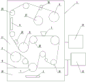
图1为本发明的卷绕式设备的一种实施方式的结构示意图;Fig. 1 is a schematic structural view of an embodiment of a winding device of the present invention;
图2为本发明中的图案生成辊的一种实施方式的结构示意图;Fig. 2 is a schematic structural view of an embodiment of a pattern generating roller in the present invention;
图3为本发明中的图案生成辊的另一种实施方式的结构示意图。Fig. 3 is a structural schematic diagram of another embodiment of the pattern generating roller in the present invention.
具体实施方式Detailed ways
下面结合附图进一步说明本发明的实施方式。应当理解的是,此处描述的具体实施方式仅用于举例说明和解释本发明,并不是用于限制本发明。Embodiments of the present invention will be further described below in conjunction with the accompanying drawings. It should be understood that the specific embodiments described here are only used to illustrate and explain the present invention, not to limit the present invention.
图1为本发明的卷绕式设备的一种实施方式的结构示意图,如图所示,本发明提供一种用于石墨烯复合薄膜制备的卷绕式设备,主要包括腔室1、蒸发模块2、涂覆模块3、定型模块4和卷绕系统;卷绕系统包括放卷辊5、收卷辊6、蒸发主辊7和图案生成辊8;在腔室1内通过隔板9分隔为蒸发工作区10和非蒸发工作区11,蒸发模块2设置在蒸发工作区10内;图案生成辊8布置在涂覆模块3和定型模块4之间;图案生成辊8通过负压吸收对绕经图案生成辊8的柔性基膜上尚未成型的湿膜层进行部分去除,从而在柔性基膜上形成具有特定图案的石墨烯复合薄膜。Fig. 1 is a schematic structural view of an embodiment of the roll-up equipment of the present invention, as shown in the figure, the present invention provides a kind of roll-up equipment for the preparation of graphene composite film, mainly including chamber 1,
腔室1上设置有真空系统12和充气系统13;真空系统12用于在腔室1内创造清洁的真空环境,充气系统用于充入工作气体。在石墨烯复合薄膜制备前,先通过真空系统12将腔室1内的气体抽除,使腔室内的真空度达到10Pa以上(即压力达到10Pa以下),然后通过充气系统13向腔室内的非蒸发工作区11通入制备石墨烯复合薄膜所需的工作气体,控制腔室内的非蒸发工作区11的气体压力在0.01MPa~0.1MPa范围内。蒸发主辊7跨跃蒸发工作区和非蒸发工作区布置,隔板9与蒸发主辊7辊面的间隙在1-5mm范围内。腔室1上还设置有用于测量环境参数的压力表、湿度表及温度表。The chamber 1 is provided with a
蒸发主辊7位于放卷辊5的下游和涂覆模块3的上游;蒸发模块2位于蒸发主辊7的下方,用于通过真空蒸发镀膜在柔性基膜表面沉积催化剂膜层。The evaporation
涂覆模块3将石墨烯复合材料涂覆在柔性基膜表面的催化剂膜层之上,形成涂覆层;在涂覆模块3下游设置有生长辊22;柔性基膜绕经生长辊22时,涂覆层在涂覆层之下的催化剂的作用下催化生长成石墨烯复合湿膜层。The
在图案生成辊8和定型模块4之间设置有膜厚监测装置23,膜厚监测装置23对湿膜层进行在线膜厚监测;涂覆模块3根据接收到的膜厚监测信号对石墨烯复合材料的供给量进行动态反馈控制,从而在线调节石墨烯复合薄膜的膜厚。A film
涂覆模块3包括布置在柔性基膜幅宽方向上的多个涂覆单元;膜厚监测装置23在柔性基膜幅宽方向上对湿膜层进行多点在线膜厚监测;涂覆单元会根据与该涂覆单元对应区域上的膜厚监测信号进行动态反馈控制,在线调节该区域上的石墨烯复合薄膜膜厚。The
定型模块4位于图案生成辊8的下游;定型模块4采用光照加热或烘干箱加热,对湿膜层进行干燥定型,使湿膜层形成石墨烯复合薄膜。定型模块4的加热温度区间为100℃~150℃。在定型模块4的下游设置有冷却辊24,冷却辊24对经过加热定型后的石墨烯复合薄膜进行降温冷却。The sizing module 4 is located downstream of the pattern generating roller 8; the sizing module 4 uses light heating or oven heating to dry and shape the wet film layer, so that the wet film layer forms a graphene composite film. The heating temperature range of the shaping module 4 is 100° C. to 150° C.
在蒸发主辊7的下游布置有控温辊25;控温辊25的控温区间为40 ~ 100℃;控温辊25将绕经控温辊的柔性基膜的温度调节至催化反应温度范围内。A
定型模块4的下游设置有层压辊26,层压辊为2个,相对布置;腔室1内设置有保护膜卷辊27。层压辊用于将来自保护膜卷辊的保护膜压制覆盖在定型后的石墨烯复合薄膜表面,对柔性基膜上的石墨烯复合薄膜表面进行保护,防止石墨烯复合薄膜在收卷和运输过程中受到损伤;保护膜优选热剥离胶带。在层压辊的上游和下游均设置有去静电装置。优选地,层压辊上设置有用于测量层压辊之间对压压力的压力传感器和压力控制器,通过压力传感器反馈,能够实时监控和调节层压辊之间的对压压力,保证保护膜压制在石墨烯复合薄膜表面的同时不会损伤薄膜。A
图案生成辊8设置在涂覆模块3的下游。图2为本发明中的图案生成辊的一种实施方式的结构示意图,如图所示,图案生成辊8为双层机构,包括内辊14和外辊15;外辊15的辊面为网状结构,上面布置有网孔阵列;内辊14的辊壁上布置有吸收孔阵列,吸收孔阵列中的吸收孔16与网孔阵列中的网孔17之间通过吸收管道18相连;内辊14内部为空腔结构,内辊14的端部与低真空泵19相连,低真空泵19将内辊14的内部抽成相对于腔室内气压的负压。A pattern generating roller 8 is arranged downstream of the
内辊14的辊壁内侧设置有遮掩筒插槽;遮掩筒插槽内可插入遮掩筒20,遮掩筒20的展开形状与要在柔性基膜上形成的石墨烯复合薄膜具有的特定图案相对应;遮掩筒20从内辊辊壁内侧对辊壁上的吸收孔阵列中某些吸收孔进行遮挡密封;图案生成辊8工作时,内辊持续稳定的负压会从那些未被遮挡的吸收孔经由与之相连的吸收管道和网孔对覆盖在这些网孔上的湿膜层产生负压吸收,从而对绕经图案生成辊的柔性基膜上的这部分湿膜层进行去除。The inner side of the roller wall of the
通过控制低真空泵19的排气速度,可以调节图案生成辊对湿膜层的负压吸收力度,对覆盖在网孔上的这部分湿膜层进行完全去除或部分去除。By controlling the exhaust speed of the
图3为本发明中的图案生成辊的另一种实施方式的结构示意图。如图所示,在这种实施方案中,图案生成辊8还包括控制器;在吸收管道18上设置有电控阀门21;控制器接收到图案生成指令后,根据预设的图案生成程序开启某些吸收管道上的电控阀门,内辊的负压会从这些吸收管道经由与之相连的吸收孔和网孔对覆盖在这些网孔上的湿膜层产生负压吸收,从而对绕经辊体的柔性基膜上的这部分湿膜层进行去除。控制器可单独对某些吸收管道上的电控阀门开度进行调节,来单独控制与这些吸收管道相连的受控网孔对湿膜层的负压吸收力度,从而对覆盖在受控网孔上的湿膜层进行完全去除或部分去除。控制器通过分别控制多个相邻网孔对湿膜层的负压吸收力度,使这些相邻网孔的负压吸收力度之间形成渐变的趋势,从而使覆盖在这些相邻网孔上的湿膜层形成深度连续渐变的沟槽图案。另外,控制器通过分别控制多个区域的网孔对湿膜层的负压吸收力度,还可以在湿膜层的多个区域上形成深浅各异的图案。Fig. 3 is a structural schematic diagram of another embodiment of the pattern generating roller in the present invention. As shown in the figure, in this embodiment, the pattern generating roller 8 also includes a controller; an electronically controlled
本发明的用于石墨烯复合薄膜制备的卷绕式设备的工作过程主要包括:The working process of the roll-up equipment for the preparation of graphene composite film of the present invention mainly comprises:
(1)启动蒸发模块进行真空蒸发镀膜,在绕经蒸发主辊的柔性基膜表面沉积催化剂膜层;启动蒸发模块下游的涂覆模块,涂覆模块将石墨烯复合材料涂覆在柔性基膜表面的催化剂膜层之上,形成涂覆层;在涂覆模块下游设置有生长辊;柔性基膜绕经生长辊时,涂覆层在涂覆层之下的催化剂的作用下催化生长成石墨烯复合湿膜层;(1) Start the evaporation module for vacuum evaporation coating, and deposit a catalyst film layer on the surface of the flexible base film that passes through the evaporation main roller; start the coating module downstream of the evaporation module, and the coating module coats the graphene composite material on the flexible base film On the catalyst film layer on the surface, a coating layer is formed; a growth roll is arranged downstream of the coating module; when the flexible base film passes through the growth roll, the coating layer is catalyzed and grown into graphite under the action of the catalyst under the coating layer vinyl composite wet film layer;
(2)设置在生长辊下游的图案生成辊通过负压吸收过程对绕经辊体的柔性基膜上尚未成型的湿膜层进行部分去除,使湿膜层产生设定的图案;(2) The pattern forming roller arranged downstream of the growing roller partially removes the unformed wet film layer on the flexible base film wound around the roller body through a negative pressure absorption process, so that the wet film layer produces a set pattern;
(3)通过设置在图案生成辊下游的定型模块对湿膜层进行加热干燥定型,使湿膜层形成石墨烯复合薄膜;定型模块采用光照加热或烘干箱加热;形成的石墨烯复合薄膜具有特定的图案。(3) The wet film layer is heated, dried and shaped through the shaping module arranged downstream of the pattern generating roller, so that the wet film layer forms a graphene composite film; the shaping module is heated by light or a drying oven; the formed graphene composite film has specific patterns.
在启动蒸发模块之前,要通过真空系统对腔室进行抽真空,当腔室内的真空度达到设定值时,通过充气系统向非蒸发工作区充入工作气体,并控制非蒸发工作区的气体压力在0.01MPa~0.1MPa范围内。Before starting the evaporation module, the chamber should be evacuated through the vacuum system. When the vacuum degree in the chamber reaches the set value, the working gas will be filled into the non-evaporative working area through the inflation system, and the gas in the non-evaporative working area will be controlled. The pressure is in the range of 0.01MPa~0.1MPa.
在图案生成辊的下游还设置有膜厚监测装置,膜厚监测装置对湿膜层进行在线膜厚监测;涂覆模块根据接收到的膜厚监测信号对石墨烯复合材料的供给量进行动态反馈控制,从而在线调节石墨烯复合薄膜的膜厚。膜厚监测装置在柔性基膜幅宽方向上对湿膜层进行多点在线膜厚监测;涂覆单元会根据与该涂覆单元对应区域上的膜厚监测信号进行动态反馈控制,在线调节该区域上的石墨烯复合薄膜膜厚。A film thickness monitoring device is also installed downstream of the pattern generating roller, and the film thickness monitoring device performs online film thickness monitoring on the wet film layer; the coating module dynamically feeds back the supply of the graphene composite material according to the received film thickness monitoring signal Control, so as to adjust the film thickness of the graphene composite film online. The film thickness monitoring device performs multi-point online film thickness monitoring on the wet film layer in the width direction of the flexible base film; the coating unit will perform dynamic feedback control according to the film thickness monitoring signal on the area corresponding to the coating unit, and adjust the film thickness online. The film thickness of the graphene composite thin film on the region.
Claims (7)
Priority Applications (1)
| Application Number | Priority Date | Filing Date | Title |
|---|---|---|---|
| CN202110992659.XA CN113684464B (en) | 2021-08-27 | 2021-08-27 | Winding type equipment for preparing graphene composite film |
Applications Claiming Priority (1)
| Application Number | Priority Date | Filing Date | Title |
|---|---|---|---|
| CN202110992659.XA CN113684464B (en) | 2021-08-27 | 2021-08-27 | Winding type equipment for preparing graphene composite film |
Publications (2)
| Publication Number | Publication Date |
|---|---|
| CN113684464A CN113684464A (en) | 2021-11-23 |
| CN113684464B true CN113684464B (en) | 2023-06-02 |
Family
ID=78583221
Family Applications (1)
| Application Number | Title | Priority Date | Filing Date |
|---|---|---|---|
| CN202110992659.XA Active CN113684464B (en) | 2021-08-27 | 2021-08-27 | Winding type equipment for preparing graphene composite film |
Country Status (1)
| Country | Link |
|---|---|
| CN (1) | CN113684464B (en) |
Families Citing this family (1)
| Publication number | Priority date | Publication date | Assignee | Title |
|---|---|---|---|---|
| CN120174330A (en) * | 2025-05-20 | 2025-06-20 | 合肥东昇智能装备股份有限公司 | Composite film forming production equipment and production method thereof |
Family Cites Families (19)
| Publication number | Priority date | Publication date | Assignee | Title |
|---|---|---|---|---|
| DE19527604A1 (en) * | 1995-07-28 | 1997-01-30 | Leybold Ag | Method and device for producing metal-free strips in metal vapor deposition |
| RU2332523C2 (en) * | 2002-12-26 | 2008-08-27 | Топпан Принтинг Ко., Лтд. | Vacuum deposition device and method of film production by vacuum deposition |
| US20100006030A1 (en) * | 2006-06-23 | 2010-01-14 | Ulvac, Inc. | Take-up type vacuum vapor deposition apparatus |
| US20100009082A1 (en) * | 2006-10-06 | 2010-01-14 | Ulvac, Inc. | Roll-to-roll vacuum deposition apparatus |
| EP2088220B1 (en) * | 2007-03-09 | 2010-12-22 | Panasonic Corporation | Deposition apparatus and method for manufacturing film by using deposition apparatus |
| RU2449050C1 (en) * | 2008-04-14 | 2012-04-27 | Улвак, Инк. | Winding-type vacuum deposition plant |
| CN201495277U (en) * | 2009-06-22 | 2010-06-02 | 杭州晶鑫镀膜包装有限公司 | Vacuum winding aluminized film device |
| WO2012124246A1 (en) * | 2011-03-11 | 2012-09-20 | パナソニック株式会社 | Thin-film production method and production device |
| EP2508646A1 (en) * | 2011-04-05 | 2012-10-10 | Bayer Material Science AG | A process for multi-layer continuous roll-to-roll coating |
| CN203080288U (en) * | 2012-12-18 | 2013-07-24 | 连云港春江机械有限公司 | Negative pressure pattern cutting device |
| CN102976318B (en) * | 2012-12-21 | 2015-04-15 | 重庆墨希科技有限公司 | Reel-to-reel graphene preparation apparatus |
| KR20150041377A (en) * | 2013-10-08 | 2015-04-16 | 송보경 | a chemical vapor deposition for flexible film |
| CN104608370A (en) * | 2015-02-09 | 2015-05-13 | 上海交通大学 | Roll-to-roll based UV cured polymer film surface microstructure processing system and method |
| CN105970158A (en) * | 2016-06-27 | 2016-09-28 | 安徽赛福电子有限公司 | Evaporation technology of metalized safety thin film of capacitor |
| CN107415329B (en) * | 2017-09-25 | 2019-01-08 | 绥阳县双龙纸业有限公司 | A kind of embossing method for papermaking |
| CN108933048B (en) * | 2018-07-18 | 2020-09-15 | 广东迈特斐薄膜科技有限公司 | Manufacturing equipment and manufacturing process of metallized film for low-power-loss capacitor |
| CN110904426A (en) * | 2019-12-24 | 2020-03-24 | 苏州昆岭薄膜工业有限公司 | Production equipment and production method of aluminized 8-micron nylon film |
| CN112725760A (en) * | 2021-02-07 | 2021-04-30 | 厦门海辰新材料科技有限公司 | Evaporation coating equipment and coating method of substrate |
| CN112813400B (en) * | 2021-03-31 | 2024-05-24 | 泊肃叶科技(沈阳)有限公司 | Double-sided multi-station winding type vacuum coating machine |
-
2021
- 2021-08-27 CN CN202110992659.XA patent/CN113684464B/en active Active
Also Published As
| Publication number | Publication date |
|---|---|
| CN113684464A (en) | 2021-11-23 |
Similar Documents
| Publication | Publication Date | Title |
|---|---|---|
| CN101378095B (en) | Method and equipment for producing solar array back film | |
| CN105752968A (en) | Reel-to-reel continuous graphene film growth equipment | |
| CN202427624U (en) | Pole-piece drying system of pole-piece coating machine | |
| CN102011323A (en) | A dry process artificial leather manufacturing machine | |
| CN113603081B (en) | Preparation method of graphene composite film | |
| CN113684464A (en) | A kind of winding device for the preparation of graphene composite film | |
| CN105665222A (en) | Multicoating device capable of achieving one-time molding | |
| CN113650277B (en) | Pattern generating roller device for winding film forming equipment | |
| CN216006006U (en) | Winding type equipment | |
| CN202492573U (en) | Multi-technological-cavity double-sided coating PECVD (Plasma Enhanced Chemical Vapor Deposition) device | |
| CN201158699Y (en) | Web Coater | |
| CN222100501U (en) | A rewetting device for graphene film coating machine | |
| CN1958285A (en) | Hot pressing device for jointing overlay film dryed by drying tunnel, and method for gluing overlay film by painting water | |
| CN202558929U (en) | Continuous film coating device | |
| CN216827919U (en) | Integrated production device for growth and rolling of graphene-reinforced metal composite material | |
| CN216972664U (en) | Magnetron sputtering gas distribution device for improving gas distribution uniformity | |
| CN102839558B (en) | Papermaking equipment, papermaking method and living paper | |
| WO2020118873A1 (en) | Reaction chamber structure of plasma deposition furnace | |
| CN207072970U (en) | Reinforced graphite alkene coating thin film equipment based on PECVD | |
| CN222659159U (en) | Pole piece fold prevention device | |
| CN107415421B (en) | A kind of integration silicon rubber Compound Fabric production equipment | |
| CN102133563A (en) | Device for dynamically and continuously preparing high-temperature superconductivity belt material by non-fluorine chemical solution sedimentation method | |
| CN216032484U (en) | Pattern generating roller device | |
| CN219073491U (en) | A polar piece baking device | |
| CN207449339U (en) | A kind of integration silicon rubber Compound Fabric production equipment |
Legal Events
| Date | Code | Title | Description |
|---|---|---|---|
| PB01 | Publication | ||
| PB01 | Publication | ||
| SE01 | Entry into force of request for substantive examination | ||
| SE01 | Entry into force of request for substantive examination | ||
| GR01 | Patent grant | ||
| GR01 | Patent grant | ||
| TR01 | Transfer of patent right | ||
| TR01 | Transfer of patent right |
Effective date of registration: 20250925 Address after: 332000 Jiangxi Province Jiujiang City Ruichang City Beihuan Road ZhiZao Town Anding Garden Patentee after: Ruichang Institute of nuclear physics applications Country or region after: China Address before: 110179 no.6-5, Qixia street, Hunnan District, Shenyang City, Liaoning Province (1-12-2) Patentee before: Liaoning molecular flow technology Co.,Ltd. Country or region before: China |