Disclosure of Invention
The present invention is directed to solving at least one of the problems of the prior art. Therefore, the invention provides the basic detonator mold transferring device which can reduce the falling height of the basic detonator in the process of transferring the basic detonator and improve the safety coefficient in the transferring process.
The invention also provides a mold transfer machine with the basic detonator mold transfer device.
The basic detonator rotary die device according to the embodiment of the first aspect of the invention is used for transferring the basic detonator in the die to be transferred into the target die, and comprises the following components:
the first flow channel seat assembly comprises a first flow channel seat and a first opening and closing assembly, the first flow channel seat is provided with a plurality of first through holes extending along the vertical direction, each first through hole is used for receiving the basic detonator in the mold to be transferred, and each first through hole comprises a first upper orifice and a first lower orifice; the first opening and closing assembly comprises a first opening and closing plate and a first driving assembly, and the first driving assembly is used for driving the first opening and closing plate to move so as to close or open the first lower hole of each first through hole;
the second flow channel seat assembly comprises a second flow channel seat and a second opening and closing assembly, the second flow channel seat is located below the first flow channel seat, the second flow channel seat is provided with a plurality of second through holes extending in the vertical direction, each second through hole is used for transferring the basic detonators into the target mold, and the number of the first through holes is equal to that of the second through holes; each second through hole comprises a second upper orifice and a second lower orifice, the second upper orifice of each second through hole can be communicated with the first lower orifice of each first through hole one by one, and the arrangement mode of the second lower orifice of each second through hole on the bottom surface of the second flow channel seat is different from the arrangement mode of the first upper orifice of each first through hole on the top surface of the first flow channel seat; the second opening and closing assembly comprises a second opening and closing plate and a second driving assembly, and the second driving assembly is used for driving the second opening and closing plate to move so as to close or open the second lower hole of each second through hole.
The basic detonator rotary die device provided by the embodiment of the invention at least has the following beneficial effects: the plurality of first through holes of the first flow channel seat are used for receiving basic detonators in a mold to be transferred, the second flow channel seat is positioned below the first flow channel seat, each second through hole of the second flow channel seat is used for transferring the basic detonators into a target mold, and second upper orifices of each second through hole can be communicated with first lower orifices of each first through hole one by one; therefore, when the second upper orifices of the second through holes are communicated with the first lower orifices of the first through holes one by one, the basic detonators can be transferred into a target mold through the first flow channel seat and the second flow channel seat in sequence, and meanwhile, the arrangement mode of the second lower orifices of the second through holes on the bottom surface of the second flow channel seat is different from the arrangement mode of the first upper orifices of the first through holes on the top surface of the first flow channel seat, namely the number of the basic detonators is not changed through the conversion of the first through holes and the second through holes, but the arrangement mode is changed, so that the basic detonators can be transferred into the target mold with different arrangement modes and higher accommodation density as required; the first driving assembly is used for driving the first opening plate to move so as to seal or open a first lower hole opening of each first through hole, the second driving assembly is used for driving the second opening plate to move so as to seal or open a second lower hole opening of each second through hole, therefore, when the basic detonator drops to the first flow channel seat from the mold to be transferred, the basic detonator can be blocked by the first opening plate, when the basic detonator drops to the second flow channel seat from the first flow channel seat, the basic detonator can be blocked by the second opening plate, and finally, the basic detonator drops to the target mold from the second flow channel seat.
According to some embodiments of the invention, further comprising a third flow channel seat assembly, the third flow channel seat assembly comprising:
the third flow channel seat is positioned between the first flow channel seat and the second flow channel seat, the third flow channel seat is provided with a plurality of third through holes extending in the vertical direction, and the number of the third through holes is equal to that of the first through holes; each of the third through holes includes a third upper orifice and a third lower orifice, the third upper orifice of each of the third through holes is capable of communicating with the first lower orifice of each of the first through holes one by one, and the third lower orifice of each of the third through holes is capable of communicating with the second upper orifice of each of the second through holes one by one;
and the third opening assembly comprises a third opening plate and a third driving assembly, and the third driving assembly is used for driving the third opening plate to move so as to close or open the third lower hole of each third through hole.
According to some embodiments of the invention, the second through hole has an inner diameter gradually decreasing from top to bottom.
According to some embodiments of the present invention, a first slot is disposed between the first flow channel seat and the second flow channel seat, the first driving assembly is configured to drive the first opening and closing plate to be inserted into the first slot to close the first lower aperture of each of the first through holes, and the first driving assembly is configured to drive the first opening and closing plate to be separated from the first slot to open the first lower aperture of each of the first through holes.
According to some embodiments of the invention, further comprising a receiving component, the receiving component comprising:
the guide die assembly comprises a guide die and a mounting frame, the mounting frame is used for placing the target die, the guide die is fixedly connected with the mounting frame, the guide die is provided with a plurality of fourth through holes extending along the vertical direction, each fourth through hole comprises a fourth upper orifice, and at least one part of the fourth upper orifices can be in one-to-one communication with at least one part of the second lower orifices of the second through holes;
the lifting assembly comprises a positioning platform and a lifting driving assembly, the positioning platform is used for placing the target die, the positioning platform is located below the guide die, the lifting driving assembly is installed on the installation frame, and the lifting driving assembly is used for driving the positioning platform to move in the vertical direction so as to enable the positioning platform to be close to or far away from the guide die.
According to some embodiments of the invention, each of the second through holes is arranged in a rectangular array, each of the fourth through holes is arranged in a rectangular array, a lateral pitch of the rectangular array of the second through holes is larger than a lateral pitch of the rectangular array of the fourth through holes, and the receiving assembly further includes a lateral driving assembly for driving the guide die to move along a lateral direction of the rectangular array of the second through holes.
According to some embodiments of the invention, the longitudinal pitch of each rectangular array of second through holes is greater than the longitudinal pitch of each rectangular array of fourth through holes, and the receiving assembly further comprises a longitudinal driving assembly for driving the guide die to move along the longitudinal direction of each rectangular array of second through holes.
According to some embodiments of the invention, the second opening and closing assembly is provided with a plurality of groups, and each group of the second opening and closing assemblies is used for respectively closing or opening the lower hole of a part of the second through hole.
According to some embodiments of the invention, each of the second opening plates is provided with a plurality of fifth through holes, the number of the fifth through holes is less than the number of the second through holes, and each of the fifth through holes of each of the second opening plates can communicate with one of the second lower ports of a part of the second through holes.
According to a second aspect of the invention, the transfer molding machine comprises the basic detonator transfer molding device.
The rotary die machine provided by the embodiment of the invention has at least the following beneficial effects: by using the basic detonator mold transferring device, the firing probability of the basic detonator can be reduced, and the safety factor of the mold transferring machine is improved.
Additional aspects and advantages of the invention will be set forth in part in the description which follows and, in part, will be obvious from the description, or may be learned by practice of the invention.
Drawings
The invention is further described with reference to the following figures and examples, in which:
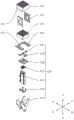
FIG. 1 is a perspective view of a basic detonator transfer mold apparatus according to an embodiment of the present invention;
FIG. 2 is a perspective view of another angle of the base detonator transfer mold apparatus of FIG. 1;
FIG. 3 is a top view of the first, second and third flow channel seats of the base detonator transfer mold apparatus of FIG. 1;
FIG. 4 is a cross-sectional view of the first, second and third flow channel seats of FIG. 3 taken along section A-A;
fig. 5 is a perspective view of a first opening and closing assembly of the base detonator transfer mold apparatus of fig. 1;
fig. 6 is a perspective view of a second opening and closing assembly of the base detonator transfer mold apparatus of fig. 1;
figure 7 is a perspective view of a receiving assembly of the base detonator transfer mold apparatus of figure 1;
figure 8 is a perspective view of the guide die assembly and lifting assembly of the base detonator transfer device of figure 1;
figure 9 is an exploded view of the guide die assembly and lifting assembly of the base detonator transfer device of figure 1;
fig. 10 is a bottom view of the second runner seat and the guide die of the base detonator transfer die apparatus of fig. 1;
FIG. 11 is a cross-sectional view of the second flow field block and guide die of FIG. 10 taken along section B-B;
figure 12 is a perspective view of the transverse drive assembly and the longitudinal movement assembly of the base detonator transfer mold apparatus of figure 1;
figure 13 is an exploded view of the transverse drive assembly and the longitudinal movement assembly of the base detonator transfer mold apparatus of figure 1;
FIG. 14 is a perspective view of a discharge assembly of the base detonator transfer mold apparatus of FIG. 1;
FIG. 15 is a schematic view of the basic detonator mold transferring device of FIG. 1 after transferring the basic detonator to the target mold for the first time;
FIG. 16 is a schematic view of the basic detonator mold transferring device in FIG. 1 after transferring the basic detonator to the target mold for the second time;
fig. 17 is a schematic diagram of the basic detonator mold transferring device in fig. 1 after transferring the basic detonator to the target mold for the third time;
fig. 18 is a schematic diagram of the basic detonator mold transferring device in fig. 1 after transferring the basic detonator to the target mold for the fourth time.
Reference numerals: a first flow channel seat assembly 100, a first flow channel seat 110, a first through hole 111, a first slot 112, a first opening/closing assembly 120, a first driving assembly 121, and a first opening/closing plate 122;
a third flow channel seat assembly 200, a third flow channel seat 210, a third through hole 211, and a third slot 212;
a second flow channel seat assembly 300, a second flow channel seat 310, a second through hole 311, a second opening and closing assembly 320, a second driving assembly 321, a second opening and closing plate 322, and a fifth through hole 323;
the device comprises a receiving assembly 400, a guide die assembly 410, a guide die 411, a mounting frame 412, a vertical plate 413, a placing plate 414, an avoiding hole 415, a fourth through hole 416, a lifting assembly 420, a first clamping block 421, a second clamping block 422, a positioning plate 423, a pneumatic clamping jaw 424, a lifting cylinder 425, a fixed block 426, a fixed plate 427, a transverse driving assembly 430, a transverse driving cylinder 431, a first sliding assembly 432, a transverse base plate 433, a first through hole 434, a longitudinal driving assembly 440, a longitudinal driving cylinder 441, a second sliding assembly 442, a longitudinal base plate 443 and a second through hole 444;
a frame 500;
a target mold 600, a storage hole 610;
discharge assembly 700, discharge cylinder 710, push plate 720.
Detailed Description
Reference will now be made in detail to embodiments of the present invention, examples of which are illustrated in the accompanying drawings, wherein like or similar reference numerals refer to the same or similar elements or elements having the same or similar function throughout. The embodiments described below with reference to the accompanying drawings are illustrative only for the purpose of explaining the present invention, and are not to be construed as limiting the present invention.
In the description of the present invention, it should be understood that the orientation or positional relationship referred to in the description of the orientation, such as the upper, lower, front, rear, left, right, etc., is based on the orientation or positional relationship shown in the drawings, and is only for convenience of description and simplification of description, and does not indicate or imply that the device or element referred to must have a specific orientation, be constructed and operated in a specific orientation, and thus, should not be construed as limiting the present invention.
In the description of the present invention, the meaning of a plurality is one or more, the meaning of a plurality is two or more, and the above, below, exceeding, etc. are understood as excluding the present numbers, and the above, below, within, etc. are understood as including the present numbers. If the first and second are described for the purpose of distinguishing technical features, they are not to be understood as indicating or implying relative importance or implicitly indicating the number of technical features indicated or implicitly indicating the precedence of the technical features indicated.
In the description of the present invention, unless otherwise explicitly limited, terms such as arrangement, installation, connection and the like should be understood in a broad sense, and those skilled in the art can reasonably determine the specific meanings of the above terms in the present invention in combination with the specific contents of the technical solutions.
In the description of the present invention, reference to the description of the terms "one embodiment," "some embodiments," "an illustrative embodiment," "an example," "a specific example," or "some examples," etc., means that a particular feature, structure, material, or characteristic described in connection with the embodiment or example is included in at least one embodiment or example of the present invention. In this specification, the schematic representations of the terms used above do not necessarily refer to the same embodiment or example. Furthermore, the particular features, structures, materials, or characteristics described may be combined in any suitable manner in any one or more embodiments or examples.
Referring to fig. 1 to 6, a basic detonator transfer molding apparatus according to an embodiment of the first aspect of the present invention for transferring a basic detonator in a mold to be transferred into a target mold 600 (refer to fig. 1) includes a first flow field seat assembly 100 and a second flow field seat assembly 300. The first flow channel seat assembly 100 includes a first flow channel seat 110 and a first opening and closing assembly 120, the first flow channel seat 110 is provided with a plurality of first through holes 111 extending in an up-down direction, each first through hole 111 is used for receiving a base detonator in a mold to be transferred, and each first through hole 111 includes a first upper orifice and a first lower orifice. The first opening and closing assembly 120 includes a first driving assembly 121 and a first opening and closing plate 122 (refer to fig. 5), and the first driving assembly 121 is used for driving the first opening and closing plate 122 to move so as to close or open the first lower aperture of each first through hole 111.
The second flow field seat assembly 300 includes a second flow field seat 310 and a second shutter assembly 320. The second flow field seat 310 is located below the first flow field seat 110, the second flow field seat 310 is provided with a plurality of second through holes 311 extending in the up-down direction, each second through hole 311 is used for transferring the base detonators into the target mold 600, and the number of the first through holes 111 is equal to the number of the second through holes 311. Each of the second through holes 311 includes a second upper orifice and a second lower orifice, and the second upper orifice of each of the second through holes 311 can communicate with the first lower orifice of each of the first through holes 111 one by one. The arrangement of the second lower orifices of the second through holes 311 on the bottom surface of the second flow field plate 310 is different from the arrangement of the first upper orifices of the first through holes 111 on the top surface of the first flow field plate 110. The second opening and closing assembly 320 includes a second opening and closing plate 322 and a second driving assembly 321, wherein the second driving assembly 321 is used for driving the second opening and closing plate 322 to move so as to close or open the second lower aperture of each second through hole 311.
In combination with the above, the plurality of first through holes 111 of the first flow field seat 110 are used for receiving the basic detonators in the mold to be transferred, the second flow field seat 310 is located below the first flow field seat 110, each second through hole 311 of the second flow field seat 310 is used for transferring the basic detonators into the target mold 600, and the second upper aperture of each second through hole 311 can be in one-to-one communication with the first lower aperture of each first through hole 111. Thus, when the second upper orifice of each second through-hole 311 is in one-to-one communication with the first lower orifice of each first through-hole 111, the base detonators may be transferred to the target mold 600 through the first and second flow channel seats 110 and 310 in sequence; meanwhile, the arrangement of the second lower orifices of the second through holes 311 on the bottom surface of the second flow channel seat 310 is different from the arrangement of the first upper orifices of the first through holes 111 on the top surface of the first flow channel seat 110, that is, the number of the basic detonators is not changed by switching the first through holes 111 and the second through holes 311, but the arrangement is changed, so that the basic detonators can be transferred to the target mold 600 with different arrangement and higher accommodation density as required.
The first driving assembly 121 is used for driving the first opening and closing plate 122 to move so as to close or open the first lower aperture of each first through hole 111, and the second driving assembly 321 is used for driving the second opening and closing plate 322 to move so as to close or open the second lower aperture of each second through hole 311. Therefore, the basic detonator is blocked by the first opening plate 122 when falling from the mold to be transferred into the first flow path seat 110, and the basic detonator is blocked by the second opening plate 322 when falling from the first flow path seat 110 into the second flow path seat 310, and finally, the basic detonator falls from the second flow path seat 310 into the target mold 600. In the whole dropping process, the dropping height of the basic detonator is divided into three sections, the single dropping height is small, the probability of triggering the basic detonator is lower, and the safety coefficient of the transfer process is higher.
It should be noted that the first through hole 111 extends in the up-down direction, and includes not only the case of extending in the vertical direction but also the case of extending obliquely downward (i.e., the first through hole 111 extends downward and also extends in the forward or backward direction). Other extensions in the up-down direction are also meant by this meaning.
Note that the arrangement of the second lower orifices of the second through holes 311 on the bottom surface of the second flow path seat 310 is different from the arrangement of the first upper orifices of the first through holes 111 on the top surface of the first flow path seat 110, that is, the projection of the first upper orifices of the first through holes 111 on the bottom surface of the second flow path seat 310 does not overlap with the second lower orifices of the second through holes 311 regardless of rotation or translation. By changing the arrangement of the second lower orifices of the respective second through holes 311 on the bottom surface of the second flow field seat 310, the arrangement of the base detonators as they flow out of the second through holes 311 can be changed to obtain a desired arrangement.
Specifically, the first upper apertures of the first through holes 111 are arranged on the top surface of the first flow channel seat 110 in a prismatic arrangement (refer to fig. 3), that is, there are 9 rows in the front-rear direction, wherein 5 rows have 6 first through holes 111, and the other 4 rows have 5 first through holes 111, and there are 50 first through holes 111 in total. The second lower orifices of the second through holes 311 are arranged in a matrix on the bottom surface of the second flow field plate 310 (refer to fig. 4 as appropriate), i.e., 5 rows in the front-rear direction, each row having 10 second through holes 311, for a total of 50 second through holes 311. The 4 × 5 rows of first through holes 111 are inclined forward or backward, so that each row of the 5 × 6 rows of first through holes 111 is inserted into 4 first through holes 111, thereby becoming a 5 × 10 row, and then abutting against the second through holes 311.
Specifically, the first drive assembly 121 includes a first air cylinder including a cylinder body and a piston rod, and the piston rod may extend from the cylinder body or retract into the cylinder body. The cylinder body of the first cylinder is fixedly connected with the frame 500, and the piston rod of the first cylinder is fixedly connected with the first opening-closing plate 122. After the first cylinder is communicated with the air source to work, the first opening-closing plate 122 can be driven to do linear motion. In addition, the first driving assembly 121 may also include a linear motor, the linear motor includes a stator and a mover, the stator is fixedly connected to the frame 500, and the mover is fixedly connected to the first opening plate 122. After the linear motor is powered on to work, the first opening-closing plate 122 can be driven to do linear motion.
Referring to fig. 4 and 5, in some embodiments of the invention, the base detonator transfer mold apparatus further comprises a third flow channel seat assembly 200, the third flow channel seat assembly 200 comprising a third flow channel seat 210 and a third opening assembly. The third flow channel seat 210 is located between the first flow channel seat 110 and the second flow channel seat 310, the third flow channel seat 210 is provided with a plurality of third through holes 211 extending in the vertical direction, and the number of the third through holes 211 is equal to the number of the first through holes 111. Each of the third through holes 211 includes a third upper orifice and a third lower orifice, the third upper orifice of each of the third through holes 211 can be in one-to-one communication with the first lower orifice of each of the first through holes 111, and the third lower orifice of each of the third through holes 211 can be in one-to-one communication with the second upper orifice of each of the second through holes 311. The third opening assembly includes a third opening plate and a third driving assembly for driving the third opening plate to move to close or open the third lower orifice of each third through-hole 211.
The arrangement of the second through holes 311 is limited by the length of the base detonator, the pitch of the first through holes 111 and the pitch of the second through holes 311. By arranging the third flow channel seat 210, the third flow channel seat 210 is positioned between the first flow channel seat 110 and the second flow channel seat 310, the conversion stroke of the basic detonator can be increased, and the arrangement mode of the basic detonator after the mold conversion is expanded. Meanwhile, the third opening and closing component is arranged, so that the basic detonator still can keep a small drop height.
The structure of the third opening/closing element is similar to that of the first opening/closing element 120, and the description thereof will not be repeated.
Specifically, referring to fig. 4, a third slot 212 is disposed between the third flow channel seat 210 and the second flow channel seat 310, a third driving assembly drives a third opening plate to be inserted into the third slot 212 to close the third lower orifice of each third through hole 211, and the third driving assembly drives the third opening plate to be separated from the third slot 212 to open the third lower orifice of each third through hole 211. The third slot 212 may be formed at a lower end of the third flow channel seat 210, and a gap may be also formed between the third flow channel seat 210 and the second flow channel seat 310, thereby forming the third slot 212.
Referring to fig. 4, in some embodiments of the present invention, the inner diameter of the second through hole 311 is gradually reduced from top to bottom. Therefore, when the basic detonator enters the second through hole 311, the second through hole 311 can better receive the basic detonator, and the basic detonator is not easy to be clamped; meanwhile, the inner diameter of the second lower orifice of the second through hole 311 is small, so that the falling position of the base detonator can be well restrained, and the base detonator can accurately fall into the target mold 600 (see fig. 1).
Referring to fig. 4, in some embodiments of the present invention, a first slot 112 is disposed between the first flow channel seat 110 and the second flow channel seat 310, the first driving assembly 121 is configured to drive the first opening and closing plate 122 to be inserted into the first slot 112 to close the first lower aperture of each first through hole 111, and the first driving assembly 121 is configured to drive the first opening and closing plate 122 to be separated from the first slot 112 to open the first lower aperture of each first through hole 111.
Therefore, by providing the first slot 112, the first opening and closing plate 122 can open or close the first lower aperture of each first through hole 111 conveniently. Meanwhile, the first slot 112 can guide and limit the movement of the first opening plate 122.
Specifically, the first slot 112 may be formed at the lower end of the first flow channel seat 110, and a gap may be formed between the first flow channel seat 110 and the second flow channel seat 310, so as to form the first slot 112.
Referring to fig. 7 to 9, in some embodiments of the invention, the base detonator transfer mold apparatus further comprises a receiving assembly 400, the receiving assembly 400 comprising a guide mold assembly 410 and a lifting assembly 420. The guide mold assembly 410 includes a guide mold 411 and a mounting frame 412, the mounting frame 412 is used for placing the target mold 600, and the guide mold 411 is fixedly connected with the mounting frame 412. The guide die 411 is provided with a plurality of fourth through holes 416 extending in the up-down direction, each fourth through hole 416 including a fourth upper orifice, at least a part of the fourth upper orifices being capable of communicating with at least a part of the second lower orifices of the second through holes 311 one by one.
The lifting assembly 420 includes a positioning platform for placing the target mold 600, and a lifting driving assembly installed on the mounting frame 412, wherein the positioning platform is located below the guide mold 411, and the lifting driving assembly is used for driving the positioning platform to move in the up-and-down direction, so that the positioning platform is close to or far away from the guide mold 411.
Therefore, after the target mold 600 is placed on the positioning platform, the lifting driving assembly drives the positioning platform to move upwards, so that the positioning platform is close to the guide mold 411, and the target mold 600 is attached to the guide mold 411. After the base detonators in the second flow seat 310 fall off, the base detonators fall into the guide die 411 and the target die 600; then, the lifting driving assembly drives the positioning platform to move downwards, so that the positioning platform is far away from the guiding mold 411. The guide die 411 can make up for the defect of insufficient height of the target die 600, and guide the basic detonator when the basic detonator falls off, so that the basic detonator accurately falls into the target die 600.
Specifically, referring to fig. 8 and 9, the mounting frame 412 includes two vertical plates 413 and a placing plate 414, the two vertical plates 413 are provided, the upper ends of the two vertical plates 413 are respectively fixedly connected to the guide mold 411 through screws, the upper ends of the two vertical plates 413 are fixedly connected to the placing plate 414 through screws, the placing plate 414 is provided with a avoiding hole 415, and the avoiding hole 415 is used for a positioning platform to pass through, so as to jack up an empty target mold 600 placed on the placing plate 414, and make the target mold 600 closely attached to the guide mold 411. After the target mold 600 is filled with the base detonators, the positioning platform is lowered, and the filled target mold 600 is placed on the placing plate 414 for discharge.
Specifically, referring to fig. 9, the positioning platform includes a first clamping block 421, a second clamping block 422, a positioning plate 423, and a pneumatic clamping jaw 424. The pneumatic jaws 424 are secured to the lower surface of the retaining plate 423 by fasteners. The number of the first clamping blocks 421 is two, the two first clamping blocks 421 are distributed at intervals along the left-right direction, and the two first clamping blocks 421 are respectively fixed on the two clamping jaws of the pneumatic clamping jaw 424. One second clamping block 422 is provided, the second clamping block 422 is fixed on the upper surface of the positioning plate 423 through a fastener, and the second clamping block 422 is located in the front side area of the positioning plate 423. It should be noted that the positioning platform may pass through the avoiding hole 415 as a whole.
Specifically, referring to fig. 8 and 9, the elevation driving assembly includes an elevation cylinder 425, a fixing block 426 and a fixing plate 427, the fixing block 426 is provided in two, and the fixing plate 427 is provided in two. The upper ends of the two fixing plates 427 are fixed on the placing plate 414 through screws, the cylinder body of the lifting cylinder 425 is located between the two fixing plates 427, the cylinder body of the lifting cylinder 425 is fixed on the fixing plates 427 through screws, the piston rod of the lifting cylinder 425 is fixed on the lower surface of the positioning plate 423 through screws and the two fixing blocks 426, and therefore after the lifting cylinder 425 is connected to an air source and starts to work, the positioning platform can be driven to move in the up-and-down direction.
Thus, the elevation cylinder 425 may drive the positioning plate 423 to move upward to be in contact with the empty target mold 600 placed on the placing plate 414. During the process that the positioning plate 423 contacts the empty target mold 600, the second clamping block 422 contacts the empty target mold 600, and the upper end of the second clamping block 422 is provided with a guide slope so as to cooperate with a longitudinal base plate 443 (described later) to realize the positioning of the target mold 600 in the front-rear direction. Thereafter, the pneumatic clamping jaws 424 drive the two first clamping blocks 421 to close each other, so that the target mold 600 is clamped and positioned in the left-right direction. Finally, the lifting cylinder 425 drives the positioning plate 423 to move upwards continuously, so that the target mold 600 is tightly attached to the guide mold 411, and thus the base detonator is received.
Referring to fig. 10 to 13, it should be noted that the sectional view in fig. 11 is a sectional view after being rotated 90 ° clockwise. In some embodiments of the present invention, the second through holes 311 are arranged in a rectangular array, the fourth through holes 416 are arranged in a rectangular array, a lateral pitch of the rectangular array of the second through holes 311 (referring to fig. 10, the lateral pitch refers to a pitch of two adjacent second through holes 311 in the left-right direction) is greater than a lateral pitch of the rectangular array of the fourth through holes 416 (referring to fig. 10, the lateral pitch refers to a pitch of two adjacent fourth through holes 416 in the left-right direction), and the receiving assembly 400 further includes a lateral driving assembly 430, and the lateral driving assembly 430 is configured to drive the guide die 411 to move along the lateral direction of the rectangular array of the second through holes 311.
In order to increase the placement density of the basic detonators of the target mold 600, the lateral spacing of the rectangular array of the fourth through holes 416 of the guiding mold 411 needs to be correspondingly reduced, and at this time, the basic detonators in the second through holes 311 may not be completely transferred into the guiding mold 411 and the target mold 600 at one time. The base detonators in each second through hole 311 can be transferred into the guide die 411 and the target die 600 in multiple times by arranging the transverse driving assembly 430 such that the guide die 411 and the target die 600 move together in the transverse direction of the rectangular array of each second through hole 311.
Specifically, the lateral pitch of the rectangular array of second vias 311 may be 1.5 times, 2 times, or other multiples of the lateral pitch of the rectangular array of fourth vias 416.
Specifically, referring to fig. 12 and 13, the lateral driving assembly 430 includes a lateral driving cylinder 431, a first sliding assembly 432, and a lateral base plate 433. The cylinder body of the transverse driving cylinder 431 is fixed on the frame 500 through a screw, and the piston rod of the transverse driving cylinder 431 is fixedly connected with the transverse base plate 433. The first sliding assembly 432 comprises a sliding rail and a sliding block, the sliding rail is fixed on the frame 500 through a screw, the sliding rail is connected with the sliding block in a sliding manner, the sliding block is fixed on the transverse base plate 433 through a screw, and the first sliding assembly 432 has the functions of guiding and bearing loads. The guide die assembly 410 is provided to a transverse base plate 433 (how it is provided is described below). Accordingly, after the transverse driving cylinder 431 is ventilated, the guide mold 411 and the target mold 600 are driven to move.
Referring to fig. 10 to 13, in a further embodiment of the present invention, the longitudinal pitch of the rectangular array of the second through holes 311 is greater than the longitudinal pitch of the rectangular array of the fourth through holes 416, and the receiving assembly 400 further includes a longitudinal driving assembly 440, wherein the longitudinal driving assembly 440 is configured to drive the guiding mold 411 to move along the longitudinal direction of the rectangular array of the second through holes 311.
Similarly, to increase the placement density of the base detonators of the target mold 600, the longitudinal pitch of the rectangular array of fourth through holes 416 of the guide die 411 also needs to be reduced accordingly. The base detonators in each second through hole 311 may be transferred into the guide die 411 and the target die 600 in multiple times by providing a longitudinal driving assembly 440 to move the guide die 411 and the target die 600 together in the longitudinal direction of the rectangular array of each second through hole 311.
Specifically, referring to fig. 12 and 13, the longitudinal driving assembly 440 includes a longitudinal driving cylinder 441, a second sliding assembly 442, and a longitudinal base plate 443. The cylinder body of the longitudinal driving cylinder 441 is fixed on the transverse base plate 433 through a screw, and the piston rod of the longitudinal driving cylinder 441 is fixedly connected with the longitudinal base plate 443. The second sliding member 442 includes a guide shaft and a guide sleeve, the guide sleeve is fixed to the transverse base plate 433 by a screw, the guide shaft is fixed to the longitudinal base plate 443 by a screw, the guide shaft and the guide sleeve are slidably connected, and the second sliding member 442 has a function of guiding and bearing a load. The placing plate 414 of the guide mold assembly 410 is fixed to the longitudinal base plate 443 by screws. Thus, the guide die 411 and the target die 600 are moved after the ventilation operation of the longitudinal driving cylinder 441.
Referring to fig. 6, in a further embodiment of the present invention, the second opening and closing member 320 is provided with a plurality of sets, and each set of the second opening and closing member 320 is used for closing or opening a lower opening of a portion of the second through hole 311. Therefore, the second through holes 311 can be opened or closed in batches, so that the requirement of batch discharging of the second flow channel seat 310 is met, and further, when the transverse distance of the rectangular array of the second through holes 311 is larger than the transverse distance of the rectangular array of the fourth through holes 416, and when the longitudinal distance of the rectangular array of the second through holes 311 is larger than the longitudinal distance of the rectangular array of the fourth through holes 416, discharging of the second flow channel seat 310 is facilitated.
Referring to fig. 6, in some embodiments of the present invention, each second opening plate 322 is provided with a plurality of fifth through holes 323, the number of the fifth through holes 323 is less than the number of the second through holes 311, and each fifth through hole 323 of each second opening plate 322 can communicate with the second lower apertures of a portion of the second through holes 311 one by one. Therefore, the single second opening-closing plate 322 can discharge part of the basic detonators in the second through holes 311 at the same time through a small stroke, the action efficiency is high, and the occupied space is small.
Referring to fig. 13 and 14, in some embodiments of the invention, the basic detonator turning mold device further comprises an ejection assembly 700, and the ejection assembly 700 comprises an ejection cylinder 710 and a push plate 720. The cylinder body of the discharging cylinder 710 is fixed on the frame 500, and the piston rod of the discharging cylinder 710 is fixedly connected with the push plate 720. After the discharging cylinder 710 is connected with an air source and starts working, the discharging cylinder 710 can drive the push plate 720 to move forwards, the push plate 720 sequentially passes through the first through hole 434 of the transverse substrate 433 and the second through hole 444 of the longitudinal substrate 443, and the target mold 600 filled with the basic detonators is pushed out from the placing plate 414, so that discharging is completed.
In conjunction with the above, and with reference to fig. 15 to 18, there is illustrated how the second flow field seat 310 having the second through holes 311 arranged in a matrix of 5 × 10 transfers the base detonators having 50 shots therein to the target mold 600 having the storage holes 610 arranged in a matrix of 10 × 10. It should be noted that a single mold to be transferred is loaded with 50 basic detonators (in a prismatic arrangement, see fig. 3), and to fill the target mold 600 having 100 storage holes 610, the basic detonators of 2 molds to be transferred are transferred. Since the lateral pitch of the second through holes 311 is 2 times the lateral pitch of the storage holes 610 (or the fourth through holes 416, the distribution of the fourth through holes 416 completely coincides with the distribution of the storage holes 610, which will be exemplified below by the storage holes 610), and the longitudinal pitch of the second through holes 311 is 2 times the longitudinal pitch of the storage holes 610, the target mold 600 is filled 4 times.
First, the guide mold 411 in an initial state is attached to the right half of the second runner housing 310 (see fig. 1), and the target mold 600 is moved close to the guide mold 411 by the elevation driving assembly and attached to the guide mold 411. Thereafter, the second opening plate 322 on the right moves forward, and the basic detonators in the 25 second through holes 311 on the right side of the second runner base 310 are placed in the guide die 411 and the target die 600, and at this time, the basic detonators are placed in the storage holes 610 in the odd-numbered rows and the odd-numbered columns (see fig. 15).
Next, the guide mold 411 and the target mold 600 are moved leftward by the lateral driving unit 430, so that the 25 storage holes 610 of the target mold 600 located at the even-numbered rows and the odd-numbered columns communicate with the corresponding second through holes 311. The second opening plate 322 on the left side moves forward, and the base detonators in the 25 second through holes 311 on the left half side of the second flow path seat 310 are placed into the guide die 411 and the target die 600, and at this time, the base detonators are placed in the storage holes 610 located in the odd-numbered rows (see fig. 16).
Thereafter, the two second split plates 322 are moved backward to reload the 50-shot basic capsules in the second flow field seats 310.
Then, the guide mold 411 and the target mold 600 are moved backward by the longitudinal moving assembly 440, so that the 25 storage holes 610 of the target mold 600 positioned in the even-numbered rows and the even-numbered columns communicate with the corresponding second through holes 311. The second opening plate 322 on the right side moves forward to put the base detonators in the 25 second through holes 311 on the left half of the second flow field seat 310 into the guide die 411 and the target die 600. At this time, 75 basic detonators are placed in the target mold 600 (see fig. 17).
Finally, the guide mold 411 and the target mold 600 are moved rightward by the lateral driving unit 430, so that the 25 storage holes 610 of the target mold 600 positioned in the odd-numbered rows and the even-numbered columns communicate with the corresponding second through holes 311, and the last 25 storage holes 610 are filled, thereby completing the filling of the target mold 600.
According to a second aspect of the invention, the transfer molding machine comprises the basic detonator transfer molding device. By using the basic detonator mold transferring device, the firing probability of the basic detonator can be reduced, and the safety factor of the mold transferring machine is improved.
The embodiments of the present invention have been described in detail with reference to the accompanying drawings, but the present invention is not limited to the above embodiments, and various changes can be made within the knowledge of those skilled in the art without departing from the gist of the present invention. Furthermore, the embodiments of the present invention and the features of the embodiments may be combined with each other without conflict.