CN113683297A - Full-automatic film cutting system - Google Patents
Full-automatic film cutting system Download PDFInfo
- Publication number
- CN113683297A CN113683297A CN202110992534.7A CN202110992534A CN113683297A CN 113683297 A CN113683297 A CN 113683297A CN 202110992534 A CN202110992534 A CN 202110992534A CN 113683297 A CN113683297 A CN 113683297A
- Authority
- CN
- China
- Prior art keywords
- breaking
- glass
- piece
- small piece
- bar
- Prior art date
- Legal status (The legal status is an assumption and is not a legal conclusion. Google has not performed a legal analysis and makes no representation as to the accuracy of the status listed.)
- Granted
Links
Images


Classifications
-
- C—CHEMISTRY; METALLURGY
- C03—GLASS; MINERAL OR SLAG WOOL
- C03B—MANUFACTURE, SHAPING, OR SUPPLEMENTARY PROCESSES
- C03B33/00—Severing cooled glass
- C03B33/02—Cutting or splitting sheet glass or ribbons; Apparatus or machines therefor
- C03B33/023—Cutting or splitting sheet glass or ribbons; Apparatus or machines therefor the sheet or ribbon being in a horizontal position
- C03B33/03—Glass cutting tables; Apparatus for transporting or handling sheet glass during the cutting or breaking operations
-
- C—CHEMISTRY; METALLURGY
- C03—GLASS; MINERAL OR SLAG WOOL
- C03B—MANUFACTURE, SHAPING, OR SUPPLEMENTARY PROCESSES
- C03B33/00—Severing cooled glass
- C03B33/02—Cutting or splitting sheet glass or ribbons; Apparatus or machines therefor
- C03B33/023—Cutting or splitting sheet glass or ribbons; Apparatus or machines therefor the sheet or ribbon being in a horizontal position
- C03B33/027—Scoring tool holders; Driving mechanisms therefor
-
- C—CHEMISTRY; METALLURGY
- C03—GLASS; MINERAL OR SLAG WOOL
- C03B—MANUFACTURE, SHAPING, OR SUPPLEMENTARY PROCESSES
- C03B33/00—Severing cooled glass
- C03B33/02—Cutting or splitting sheet glass or ribbons; Apparatus or machines therefor
- C03B33/023—Cutting or splitting sheet glass or ribbons; Apparatus or machines therefor the sheet or ribbon being in a horizontal position
- C03B33/033—Apparatus for opening score lines in glass sheets
-
- Y—GENERAL TAGGING OF NEW TECHNOLOGICAL DEVELOPMENTS; GENERAL TAGGING OF CROSS-SECTIONAL TECHNOLOGIES SPANNING OVER SEVERAL SECTIONS OF THE IPC; TECHNICAL SUBJECTS COVERED BY FORMER USPC CROSS-REFERENCE ART COLLECTIONS [XRACs] AND DIGESTS
- Y02—TECHNOLOGIES OR APPLICATIONS FOR MITIGATION OR ADAPTATION AGAINST CLIMATE CHANGE
- Y02P—CLIMATE CHANGE MITIGATION TECHNOLOGIES IN THE PRODUCTION OR PROCESSING OF GOODS
- Y02P40/00—Technologies relating to the processing of minerals
- Y02P40/50—Glass production, e.g. reusing waste heat during processing or shaping
- Y02P40/57—Improving the yield, e-g- reduction of reject rates
Abstract
The present disclosure provides a full-automatic film opening system. The system generally comprises a marking device, a large piece transferring device, a large piece breaking device, a small piece transferring device and a small piece breaking device. The scribing device is used for scribing lines with preset patterns on a large glass original sheet. The large-piece transferring device is used for transferring the glass substrate with the marked line to the area corresponding to the large-piece breaking device so as to prepare for breaking operation. The large-piece breaking device is used for breaking large pieces of glass into long pieces of glass along the first scribing direction. The small piece transferring device is used for feeding the long glass broken by the large piece breaking device to the small piece breaking device. The small piece breaking device is used for breaking the long glass into single small pieces of glass. All the load transferring and breaking operations in the system are automatically completed by equipment, so that the labor intensity of workers is reduced.
Description
Technical Field
The invention relates to the field of mobile phone glass deep processing, in particular to a full-automatic film opening system.
Background
The curved glass original sheet is generally in 5 generation or 6 generation glass size specification. However, the glass required for the actual product is typically of a size below 7 inches (7 inches, 177.8 mm). In order to obtain the desired small size of glass, the purchased original sheet needs to be further divided into smaller pieces.
At present, in the industry, a manual slicing mode is generally adopted. The slicing mode has low efficiency, large labor intensity of workers and high operation cost. While some techniques exist in the prior art for automatically cutting glass using mechanical devices, these cutting devices still require manual assistance, are not intelligent enough, and are inefficient.
Therefore, it is necessary to develop a fully automatic film opening system.
Disclosure of Invention
The invention aims to overcome the problems in the prior art and provide a full-automatic film opening system, all the transferring and breaking operations in the system are automatically completed by equipment, and the labor intensity of workers is reduced.
According to an aspect of the present invention, there is provided a full-automatic film opening system, including:
the scribing device comprises a cutter and a scribing driving mechanism for driving the cutter to move, and the scribing driving mechanism drives the cutter to scribe along at least two directions;
the large glass holding mechanism is arranged on the first shifting mechanism and moves between an area above the marking device and an area above the supporting plate under the driving of the first shifting mechanism;
the large sheet breaking device is positioned on one side of the large sheet transferring device opposite to the scribing device, and the large sheet breaking device breaks glass along one of at least two scribing directions;
the small piece transferring device is positioned on one side of the large piece breaking-off device opposite to the large piece transferring device and comprises a small piece glass holding mechanism, a small piece bearing bottom plate and a second shifting mechanism, the small piece bearing bottom plate extends between the large piece breaking-off device and the second shifting mechanism, and the small piece glass holding mechanism is installed on the second shifting mechanism and driven by the second shifting mechanism to move along the other direction vertical to the moving direction of the large piece glass holding mechanism; and
and the small piece breaking device is closely adjacent to one end of the small piece bearing bottom plate and extends from one side close to the large piece breaking device to one side close to the second displacement mechanism, and the small piece breaking device breaks the glass along the other direction of the at least two scribing directions.
According to one embodiment of the present disclosure, the scribing driving mechanism includes three sets of driving mechanisms for driving the cutter to move along three directions perpendicular to each other, each set of driving mechanism includes a fixed portion and a sliding portion, the sliding portion can be displaced relative to the fixed portion under the action of the actuator, the fixed portion of the second set of driving mechanism is mounted on the sliding portion of the first set of driving mechanism, the first set of driving mechanism drives the second set of driving mechanism to move along a first transverse direction, the fixed portion of the third set of driving mechanism is mounted on the sliding portion of the second set of driving mechanism to drive the third set of driving mechanism to move along a second transverse direction perpendicular to the first transverse direction by using the second set of driving mechanism, and the cutter is arranged on the sliding portion of the third set of driving mechanism and drives the cutter to move along a vertical direction.
According to one embodiment of the present disclosure, the system includes two sets of the following devices: the large-piece transferring device, the large-piece breaking device, the small-piece transferring device and the small-piece breaking device are symmetrically arranged on two sides of the scribing device.
According to one embodiment of the disclosure, the large glass breaking device comprises a large glass supporting mechanism and a large glass breaking mechanism positioned above the large glass supporting mechanism, wherein a gap for accommodating glass is formed between the large glass breaking mechanism and the large glass breaking mechanism, and the large glass breaking mechanism can swing downwards and break the glass along one direction of at least two scribing directions.
According to one embodiment of the present disclosure, a small piece breaking device includes a small piece supporting mechanism and a small piece breaking mechanism located above the small piece supporting mechanism, the small piece breaking mechanism being capable of swinging down to break glass along another one of at least two scribing directions.
According to one embodiment of the present disclosure, the large sheet glass holding mechanism includes a plurality of vacuum chucks arranged in an array on the same horizontal plane.
According to one embodiment of the present disclosure, the scribing driving mechanism further comprises a tool bit rotary driving mechanism for driving the tool bit to rotate around the vertical axis, and the first set of driving mechanism, the second set of driving mechanism, the third set of driving mechanism and the tool bit rotary driving mechanism operate in an interpolation motion control manner.
According to one embodiment of the disclosure, the large glass supporting mechanism comprises a strip-shaped breaking bar and two sets of breaking bar supporting assemblies for supporting the breaking bar at two ends of the breaking bar, the large glass pressing and breaking mechanism comprises breaking bars and breaking bar mounting assemblies positioned at two ends of the breaking bars, the breaking bar mounting assemblies drive the breaking bars to rotate around axes parallel to the axes of the breaking bars, and the breaking bars are parallel to the breaking bars.
According to one embodiment of the disclosure, the system further comprises a frame, the breaking-off rod supporting assembly is fixedly installed on the frame and provided with a breaking-off rod actuator for driving the breaking-off rods to move upwards, and the breaking-off strip installing assembly is connected to the first shifting mechanism of the large-piece transferring device and moves synchronously with the large-piece glass holding mechanism.
According to an embodiment of the present disclosure, each set of breaking-off bar mounting assemblies includes:
a support block having a guide groove;
the breaking-off cylinder is arranged on the supporting block;
the pinch roller seat is arranged below the breaking-off air cylinder and can move up and down under the driving of the breaking-off air cylinder;
the wheel shaft of the pressing wheel is arranged on the pressing wheel seat;
the breaking-off strip seat is connected with one side of the breaking-off strip seat, a convex shaft of the guide wheel is installed on the other side of the breaking-off strip seat, one side of the breaking-off strip seat, which is provided with the convex shaft of the guide wheel, also comprises an open slot, and the pressing wheel is installed in the open slot;
and the guide wheel is arranged in the guide groove of the supporting block so as to limit the movement path of the guide wheel by using the guide groove.
According to one embodiment of the disclosure, the small piece supporting mechanism and the small piece breaking mechanism are fixedly mounted on the rack, the small piece supporting mechanism comprises a small piece breaking bar and two sets of small piece breaking bar supporting assemblies used for supporting two ends of the small piece breaking bar, the small piece breaking mechanism comprises a small piece breaking bar and two sets of small piece breaking bar mounting assemblies mounted at two ends of the small piece breaking bar, and the small piece breaking bar is parallel to the small piece breaking bar and perpendicular to the breaking bar of the large piece breaking device.
According to one embodiment of the present disclosure, a piece breaking bar supporting assembly includes:
an upper actuator including an upper actuator fixing part connected to the frame and an upper actuator lifting part movable up and down with respect to the upper actuator fixing part;
a support base, a part of which is mounted on an upper actuator lifting part of the upper actuator;
the guide wheel supporting plate is fixedly connected to the supporting seat and comprises a guide arc groove;
the small piece breaking cylinder comprises a main body and an output end which are arranged on the guide wheel supporting plate;
the small piece breaking-off pressing wheel seat is connected to the output end of the small piece breaking-off air cylinder and can move downwards under the driving of the small piece breaking-off air cylinder;
the small breaking-off pinch roller is characterized in that a wheel shaft of the small breaking-off pinch roller is arranged at the lower part of a small breaking-off pinch roller seat;
the broken bar connecting block is connected with the small broken bars at one side and connected with a convex shaft of the small broken guide wheel at the other side, the broken bar connecting block comprises a pressing wheel groove, and the small broken pressing wheel is accommodated in the pressing wheel groove;
the small piece breaking guide wheel is accommodated in the guide arc groove.
According to one embodiment of the present disclosure, the scribing apparatus further comprises a glass conveying mechanism including a scribing region, and the scribing driving mechanism drives the cutter to move above the scribing region.
According to one embodiment of the present disclosure, the first displacement mechanism can also control the large glass holding mechanism to ascend and descend in the vertical direction.
According to one embodiment of the present disclosure, the second displacement mechanism also controls the elevation of the small glass suction mechanism in the vertical direction.
According to one embodiment of the disclosure, the piece breaking-off device further comprises a piece conveying mechanism which is connected to the frame and arranged on one side of the piece breaking-off mechanism opposite to the piece bearing bottom plate for receiving and conveying the broken piece glass.
Due to the adoption of the technical scheme, compared with the prior art, the full-automatic film opening system at least has the following advantages:
the marking and conveying and marking work of the large glass sheets is completed automatically;
the full-automatic transfer of the large glass piece after marking to two stations on the side edge and the breaking and splitting work are completed;
the full-automatic glass strip moving and breaking and slicing work of the glass strip after the strip splitting to the two sides is completed, and the small glass blocks after the glass strip splitting are conveyed to the next working procedure;
the number of the suckers can be increased or decreased as required, and each piece of small glass is guaranteed to be sucked by the sucker, so that the phenomenon of chip falling is avoided, and the performance is stable and reliable;
the marked large glass sheets are simultaneously broken at the left side and the right side, so that the production benefit is improved;
all the transferring and breaking operations are fully automated, so that the labor intensity of workers is reduced.
Additional features and advantages of the disclosure will be set forth in the detailed description which follows.
Drawings
The accompanying drawings, which are included to provide a further understanding of the disclosure and are incorporated in and constitute a part of this specification, illustrate embodiments of the disclosure and together with the description serve to explain the disclosure without limiting the disclosure. In the drawings:
fig. 1 is a top perspective view of the overall structure of a fully automatic film opening system according to one embodiment of the present disclosure.
Fig. 2 is a bottom perspective view of the overall structure of a fully automatic film opening system according to one embodiment of the present disclosure.
Fig. 3 is a front perspective view of a scoring device according to one embodiment of the present disclosure.
Fig. 4 is a rear perspective view of a scoring device according to one embodiment of the present disclosure.
Fig. 5 is a bottom perspective view of a scoring device according to one embodiment of the present disclosure.
Fig. 6 is a top perspective view of a large transfer device according to one embodiment of the present disclosure.
Fig. 7 is a bottom perspective view of a large transfer device according to one embodiment of the present disclosure.
Fig. 8 is a top perspective view of a large panel breaking apparatus according to one embodiment of the present disclosure.
Fig. 9 is a bottom perspective view of a large panel breaking device according to one embodiment of the present disclosure.
FIG. 10A is an enlarged partial view of region A1 of FIG. 8; fig. 10B is a partially enlarged view of the area a2 in fig. 9.
Fig. 11 is a top perspective view of a die transfer device according to one embodiment of the present disclosure.
Fig. 12 is a bottom perspective view of a die transfer device according to one embodiment of the present disclosure.
Fig. 13 is a side perspective view of a tab severing device according to one embodiment of the present disclosure.
Fig. 14 is another side perspective view of a tab severing device according to one embodiment of the present disclosure.
Fig. 15 is a bottom perspective view of a tab severing device according to one embodiment of the present disclosure.
Description of the reference numerals
100 marking device, 101 driven roller, 102 platform, 103 conveyor belt, 104 first screw rod rear seat, 105 first linear guide rail assembly, 106 support frame, 107 second screw rod rear seat, 108 second linear guide rail assembly, 109 second screw rod assembly, 110 cutter head lifting cylinder, 111 second screw base, 112 cutter head linear guide rail assembly, 113 cutter head seat, 114 cutter head fixing plate, 115 cutter head cylinder, 116 cutter head, 117 cutter head belt, 118 cutter head motor, 119 first screw rod assembly, 120 first screw base, 121 first motor base, 122 first motor, 123 first screw rod front seat, 124 driving roller, 125 second screw rod front seat, 126 second motor base, 127 second motor, 200 large piece transfer device, 201 rack, 202 roller, 203 large piece transfer motor base, 204 large piece transfer motor, 205 large piece linear guide rail assembly, 206 large piece guide rail base plate, 207 support table strip, 208 large piece glass support plate, 209 vacuum chucks, 210 chuck support pieces, 211 chuck support screws, 212 chuck support bars, 213 large elevator plates, 214 large elevator linear guide assemblies, 215 large elevator nut bases, 216 large elevator screw rod front seats, 217 large elevator motor bases, 218 large elevator motors, 219 large elevator screw rod assemblies, 300 large breaking devices, 301 breaking bar bases, 302 pressing wheels, 303 support blocks, 304 breaking cylinders, 305 pressing wheel bases, 306 breaking bar initiators, 307 breaking bar support frames, 308 breaking bars, 309 breaking bars, 310 pointers, 311 scale identification bars, 312 guide wheels, A glass, B dust suction ports, C arc guide grooves, D open slots, E dust suction ports, 400 small piece devices, 401 small piece Y-axis motors, 402Y-axis nut coupling blocks, small piece Y-axis moving plates, 404 small piece X-axis moving plates, 405 small piece Z-axis screw rod bases, 406 small piece Z-axis screw rods, 407 small piece X-axis motor, 408 small piece X-axis motor base, 409 small piece Z-axis motor base, 410 small piece Z-axis motor, 411 small piece Z-axis linear guide rail assembly, 412 small piece sucker fixing screw, 413 small piece sucker fixing block, 414 small piece base plate, 415 small piece sucker fixing rod, 416 small piece sucker fixing rod, 417 small piece Z-axis lifting plate, 418 small piece Y-axis nut rear base, 419 small piece Y-axis screw rod assembly, 420 small piece Y-axis nut front base, 421 small piece Y-axis motor base, 422 small piece Y-axis linear guide rail assembly, 423 small piece X-axis linear guide rail assembly, 500 small piece breaking device, 501 belt supporting plate, 502 small piece conveying belt, 503 small piece breaking bar, 504 small piece breaking bar connecting block, 505 small piece breaking pressing wheel, 506 small piece breaking pressing wheel base, 507 small piece breaking cylinder, 508, 509 upper actuator, 510 guide wheel supporting plate, 511 scale display plate, 512 lower actuator supporting bar, 514 small piece driven roller, 515 small piece driving roller, 516 small piece breaking rod, 517 small piece pointer, 518 small piece breaking guide wheel, H arc groove, G pressure wheel groove, I dust collection joint and J dust collection opening.
Detailed Description
The following detailed description of specific embodiments of the present disclosure is provided in connection with the accompanying drawings. It should be understood that the detailed description and specific examples, while indicating the present disclosure, are given by way of illustration and explanation only, not limitation.
Unless defined otherwise, all technical and scientific terms used herein have the same meaning as commonly understood by one of ordinary skill in the art to which this invention belongs; the terminology used in the description presented herein is for the purpose of describing particular embodiments only and is not intended to be limiting of the invention, e.g., the terms "length," "width," "upper," "lower," "left," "right," "front," "rear," "vertical," "horizontal," "top," "bottom," "inner," "outer," etc., refer to an orientation or position based on that shown in the drawings, are for convenience of description only and are not to be construed as limiting of the present disclosure.
The terms "including" and "having," and any variations thereof, in the description and claims of this invention and the description of the above figures are intended to cover non-exclusive inclusions; the terms "first," "second," and the like in the description and in the claims, or in the drawings, are used for distinguishing between different objects and not necessarily for describing a particular sequential order. The meaning of "plurality" is two or more unless specifically limited otherwise.
In the description and claims of the present invention and in the description of the above figures, when an element is referred to as being "fixed" or "mounted" or "disposed" or "connected" to another element, it may be directly or indirectly located on the other element. For example, when an element is referred to as being "connected to" another element, it can be directly or indirectly connected to the other element.
Furthermore, reference herein to "an embodiment" means that a particular feature, structure, or characteristic described in connection with the embodiment can be included in at least one embodiment of the invention. The appearances of the phrase in various places in the specification are not necessarily all referring to the same embodiment, nor are separate or alternative embodiments mutually exclusive of other embodiments. It is explicitly and implicitly understood by one skilled in the art that the embodiments described herein can be combined with other embodiments.
For convenience of description, three coordinate axes which are mutually perpendicular in space are defined as an X axis, a Y axis and a Z axis respectively, wherein the X axis and the Y axis are two coordinate axes which are mutually perpendicular on the same transverse plane, and the Z axis is a coordinate axis in the vertical direction; the X axis, the Y axis and the Z axis are positioned in space and are mutually vertical, and three planes are respectively an XY plane, a YZ plane and an XZ plane, wherein the XY plane is a transverse plane, the XZ plane and the YZ plane are vertical planes, and the XZ plane is vertical to the YZ plane.
Referring to fig. 1 and 2, the present disclosure provides a fully automatic film opening system. The system generally includes a scribing apparatus 100, a big transfer apparatus 200, a big break apparatus 300, a small transfer apparatus 400, a small break apparatus 500, and an optional controller and frame (not shown). The scribing apparatus 100 is used to scribe lines of a predetermined pattern on a large glass original sheet. The large transfer device 200 is used to transfer the scribed glass substrates to an area corresponding to the large breaking device 300, thereby preparing for the breaking operation. The large piece breaking device 300 is used for breaking large pieces of glass into long pieces of glass along a first scribing direction. The small piece transfer device 400 is used to feed the long glass pieces cut by the large piece breaking device 300 to the small piece breaking device 500. The small piece breaking device 500 is used to break the long glass pieces into individual small pieces. The large glass described in the present disclosure refers to glass which has the same size as the original large glass and is not broken, the long glass refers to glass which is obtained after the large glass is broken for the first time and still has a scribing pattern in another direction, the small glass refers to glass which has a smaller size and is obtained after the long glass is broken again, and the small glass has no scribing pattern and has the same size (for example, 7 inches) as the glass required by the actually produced product.
Fig. 3-5 illustrate a scribing apparatus 100 according to one embodiment of the present disclosure at different viewing angles. The scribing device 100 is used for scribing lines with a predetermined pattern on a large glass original sheet so that a subsequent breaking device can break the glass along the predetermined lines. In an embodiment of the present disclosure, the scribing apparatus 100 draws two lines (including straight lines and curved lines) in different directions.
The scoring device 100 basically includes an optional glass transport mechanism, a cutter, and a scoring drive mechanism that drives the cutter to score two lines in different directions. The scribing driving mechanism can comprise a Y-axis scribing driving mechanism, an X-axis scribing driving mechanism, a Z-axis scribing driving mechanism and a cutter head rotating driving mechanism. As shown in fig. 3, the glass conveying direction is set to the Y-axis direction. The X-axis direction is defined as another lateral direction perpendicular to the Y-axis. The Z axis is vertical to both the X axis and the Y axis.
The glass conveying mechanism includes a driven roller 101, a stage 102, a conveying belt 103, a driving roller 124, and a driving motor (not shown). The platform 102 is fixedly mounted to the frame. The driven roller 101 and the driving roller 124 are rotatably mounted on the frame at a certain distance. The conveyor belt 103 is looped around the driven roller 101, the table 102, and the drive roller 124. When the driving roller 124 is driven by the motor to rotate, the conveying belt 103 is driven to roll, and the driven roller 101 is driven to rotate. As shown in fig. 3, when the drive roller 124 rotates, the glass a placed on the conveyor belt 103 can be conveyed from the sheet-feeding position to the scribing position in the direction of the illustrated arrow.
The Y-axis scribing driving mechanism is arranged on one side close to the glass scribing position and is used for driving the rest driving mechanism and the cutter to move along the Y-axis direction. The Y-axis scribing driving mechanism may include at least one first lead screw assembly, and the first lead screw assembly is composed of a first lead screw rear base 104, a first linear guide rail assembly 105, a first lead screw assembly 119, a first nut base 120, a first motor base 121, a first motor 122, and a first lead screw front base 123. Wherein, the first screw rear seat 104 and the first screw front seat 123 are fixedly arranged on the frame, the first linear guide rail assembly 105 is parallel to the glass conveying direction and arranged outside the conveyor belt 103 and the platform 102, and the height of the first linear guide rail assembly 105 is basically the same as that of the conveyor belt 103. A support frame 106 supporting the tool is slidably mounted on the first linear guide assembly 105 by means of a slide. The first lead screw assembly 119 is parallel to the first linear guide assembly 105, and is provided with a first lead screw rear seat 104 at the rear end and a first lead screw front seat 123 at the front end. It should be noted that the front-back direction mentioned here refers to the glass conveyance direction. The first nut seat 120 is disposed on the first lead screw assembly 119 and is fixedly connected to the sliding block of the supporting frame 106. A first motor 122 is mounted to the front end of the first linear guide assembly 105 with a first motor mount 121. The first nut base 120 moves along the first lead screw assembly 119 under the driving of the first motor 122, and simultaneously drives the support frame 106 to slide along the first linear guide rail assembly 105, so as to realize the movement of the tool in the Y-axis direction. That is, the first lead screw assembly 119 and its related mounting structure constitute a fixed portion of the Y-axis scribing driving mechanism, and the first nut block 120, the slider, and the like, which are slidable on the first lead screw assembly 119, constitute a sliding portion of the Y-axis scribing driving mechanism.
In some embodiments of the present disclosure, the Y-axis scribing drive mechanism comprises two sets of the first lead screw assemblies described above. Two sets of first screw rod assemblies are respectively arranged at two sides of the conveyor belt 103. The two sets of first screw assemblies move synchronously, thereby driving the two ends of the support frame 106 to move synchronously along the Y-axis direction.
The X-axis scribing drive mechanism is mounted on the Y-axis scribing drive machine by a support frame 106. The X-axis scribing driving mechanism generally comprises a second lead screw assembly, and the second lead screw assembly is composed of a second lead screw rear seat 107, a second linear guide rail assembly 108, a second lead screw assembly 109, a second screw seat 111, a second lead screw front seat 125, a second motor seat 126 and a second motor 127. The second lead screw assembly is similar in construction and operation to the first lead screw assembly, with the primary difference being that the second linear guide assembly 108 and the second lead screw assembly 109 extend in the X-axis direction and are both mounted on the support frame 106. The second motor 127 drives the second nut block 111 to move on the second screw assembly 109, and at the same time, drives the fixed plate 114 slidably mounted on the second linear guide assembly 108 to slide together, so as to move the tool on the fixed plate 114 in the X-axis direction.
The Z-axis scribing drive mechanism generally includes a tool bit linear guide assembly 112 and a tool bit lift cylinder 110 mounted on a fixed plate 114. The tool bit linear guide assembly 112 is provided with a tool bit seat 113. The tool bit seat 113 can slide up and down along the tool bit linear guide assembly 112 under the driving of the tool bit lifting cylinder 110, so as to change the height of the tool.
The cutter generally includes a cutter head cylinder 115 and a cutter head 116. The cutter head cylinder 115 is installed on the cutter head base 113, and the cutter head 116 is installed at the lower end of the cutter head cylinder 115. The bottom end of the cutter head 116 is provided with a rollable disc cutter tip. The diameter of the disc nose extends in the vertical direction. Bit cylinder 115 may be raised and lowered to control the depth of the scribe of bit 116.
The cutter head rotation driving mechanism is used for driving the cutter head to rotate around the vertical shaft. The bit rotary drive mechanism generally includes a bit motor 118 and a bit belt 117. The tool bit motor 118 is installed on the tool bit seat 113, and a first belt pulley is provided on the output end thereof. A second belt pulley is arranged at the output shaft of the cutter head cylinder 115. A cutter belt 117 is wound around the first pulley and the second pulley. The output shaft of the cutter head cylinder 115 is driven to rotate around the axis thereof by the rotation of the cutter head belt 117, and then the cutter point at the bottom is driven to rotate around the vertical axis. The cutter head rotation driving mechanism functions to control the cutting direction of the scribing cutter of the cutter head 116 to be the same as the tangential direction of the drawn curve or straight line.
In the embodiment of the disclosure, the Y-axis scribing driving mechanism, the X-axis scribing driving mechanism and the tool bit rotation driving mechanism are subjected to interpolation motion control by the controller so as to meet the requirements of longitudinal and transverse scribing and can scribe a curve shape. The first motor 122, the second motor 127, and the cutting head motor 118 are all servo motors. The cutter head cylinder 115 is a high-precision cylinder, and controls the pressure of the cutter head during scribing by adjusting the air inlet pressure so as to ensure a certain scribing depth. The upper surface of the conveyor belt 103 is divided into two areas, i.e., a sheet-on-glass area and a scribing area, to which glass is fed when scribing is required. The bit lift cylinder 110 is an adjustable stroke cylinder to facilitate the up and down displacement of the bit 116.
A large transfer device 200 according to some embodiments of the present disclosure is described below with reference to fig. 1, 6, and 7. The large transfer device 200 is used to transfer the scribed glass substrates to an area corresponding to the large breaking device 300, thereby preparing for the breaking operation.
The large transfer device 200 is disposed on the side of the scribing device in the X-axis direction. The large transfer device 200 corresponds to the scribe line region of the conveyor belt 103 in the Y-axis direction. The large transfer device 200 generally includes a first shift mechanism, a large glass holding mechanism, and a pallet 208. The first shifting mechanism comprises a large piece shifting mechanism used for enabling the large piece glass holding mechanism to move along the X-axis direction and a lifting mechanism used for enabling the large piece glass holding mechanism to move along the Z-axis direction. The large glass holding mechanism may be a vacuum suction type holding mechanism (hereinafter referred to as a large glass suction mechanism).
The large glass transfer mechanism is used to move the large glass suction mechanism between the scribing area and the corresponding area above the pallet 208. The large-piece transferring mechanism comprises a pair of large-piece transferring linear guide rail assemblies 205 arranged near two ends of a supporting plate 208 in the Y-axis direction, a pair of large-piece transferring motor bases 203, a pair of large-piece transferring motors 204, a pair of rollers 202 and a pair of racks 201. Specifically, each large transfer linear guide assembly 205 extends from the area above the pallet 208 in the X-axis direction over the entire scribing area. The two large-piece rail seat plates 206 are slidably supported on the two large-piece transfer linear rail assemblies 205 by means of sliders. Two large transfer motor bases 203 are fixed to the outer sides of the corresponding large rail base plates 206. The large transfer motor 204 is mounted on the corresponding large transfer motor base 203. The roller 202 is installed at the output end of the corresponding transfer motor. The rack 201 is fixed on the frame and cooperates with the corresponding roller 202 to form a rack pair. The large transfer motor 204 drives the rack pair to drive the large guide rail seat plate 206 to move along the X-axis direction relative to the rack.
The large-sheet lifting mechanism is used for enabling the large-sheet glass adsorption mechanism to move up and down. The large lifting mechanism may comprise a pair of large lifting linear guide rail assemblies 214, a pair of large lifting nut bases 215, a pair of large lifting screw front bases 216, a pair of large lifting motor bases 217, a pair of large lifting motors 218 and a pair of large lifting screw assemblies 219. Specifically, the large lift linear guide assembly 214 is fixed on the large guide plate 206 and is located on the other side opposite to the large transfer motor base 203. The large lift linear guide assembly 214 extends in the Z-axis direction to guide the large lift plate 213 to move in the Z-axis direction relative to the large guide rail base plate 206. The construction and operation of the large lift screw assembly 219 and the large lift screw base 215 are similar to the first screw assembly described above. To avoid repetition, a detailed description thereof is omitted. The large elevator motor 218 drives the large elevator screw assembly 219 to drive the large elevator plate 213 to move along the Z-axis direction relative to the large guide rail plate 206.
The large glass suction mechanism is used for sucking the large glass in the scribing area and transferring the glass to the area where the supporting plate 208 is located in cooperation with other components, and is also used for feeding the glass into the large breaking device 300. The large glass suction mechanism may include a support bar 207, a vacuum chuck 209, a chuck support piece 210, a chuck support screw 211, and a chuck support bar 212. Two of the support bars 207 are fixedly mounted to two large lift plates 213, respectively. The two ends of the suction cup support bar 212 are respectively supported by the two support platform bars 207. The suction cup support bar 212 can be mounted to the support bar 207 using fixing bolts that are caught in dovetail grooves of the support bar 207, and the suction cup support bar 212 can be fixed at any position on the support bar 207. A plurality of suction cup support bars 212 may be provided on the two support bars 207. Each suction cup support bar 212 may also include at least one mounting slot extending along its length. A suction cup supporting screw 211 is inserted from above the mounting groove to mount the suction cup supporting sheet 210 located below the suction cup supporting bar 212 to the suction cup supporting bar 212. A vacuum chuck 209 is installed below the chuck support piece 210. Also, the suction cup support piece 210 may be fixed at any position of the installation groove. The installation position and the number of vacuum pads 209 to be installed are determined by the number of small glasses to be transferred. Specifically, one vacuum cup 209 is ensured for each small piece of glass. Each vacuum chuck 209 is connected to a vacuum machine (not shown) through a vacuum air duct. The bottom surfaces of all vacuum cups 209 are in the same plane and arranged in an array.
The support plate 208 is used to hold a large piece of glass released by the vacuum chuck 209. The support plate 208 is located to the side of the line marking apparatus and is fixedly mounted to the frame. The height of the pallet 208 is close to the height of the upper surface of the conveyor belt 103 for ease of control.
In some embodiments of the disclosure, since the production time of glass scribing is much shorter than the glass breaking time, two sets of large-piece transferring devices and breaking devices are symmetrically arranged on two sides of the scribing device, thereby improving the production efficiency of the whole machine. Each small piece of glass corresponds to one vacuum chuck, and the position of the chuck can be adjusted at will in the X-axis and the Y-axis so as to adapt to small pieces of glass with different specifications. The bottom surfaces of all the suckers are on the same plane, so that the glass can be firmly adsorbed. The large transferring device 200 not only transfers the scribed large glass from the scribing device, but also meets the feeding requirement of the large breaking device 300, which is described in detail below. The large transfer motor 204 and the large lifting motor 218 can be servo motors.
Referring to fig. 1 and 8-10B, a large piece breaking device 300 is disposed on a side of the large piece transfer device 200 away from the conveyor belt 103. The large piece breaking device 300 is used for breaking a large piece of glass in one scribing direction (i.e., the scribing direction generally along the Y-axis). The large glass breaking device 300 mainly includes a large glass supporting mechanism and a large glass breaking mechanism. The large glass breaking mechanism is arranged above the large glass supporting mechanism.
The large glass supporting mechanism plays a role in supporting glass. The large glass supporting mechanism includes two sets of breaking-off rod supporting assemblies disposed on both sides of the supporting plate 208 in the Y-axis direction and a breaking-off rod 308 connecting the two sets of breaking-off rod supporting assemblies. Each set of breaking-off bar support assemblies generally includes a breaking-off bar actuator 306 and a breaking-off bar support frame 307. Optionally, the bulk glass support mechanism may further comprise a pointer 310 and a scale marker strip 311. The pointer 310 and the scale mark bar 311 are used for displaying the highest position of the breaking-off rod 308, which is convenient for adjusting the position of the breaking-off rod 308. Two break-off bar actuators 306 and optionally a scale marker strip 311 are mounted on the frame. The breaking-off bar support 307 and optionally the pointer 310 are mounted on the breaking-off bar actuator 306. Both ends of the breaking-off bar 308 are supported by two breaking-off bar support frames 307, respectively. The breaking-off bar actuator 306 drives the breaking-off bar support 307 and the breaking-off bar 308 thereon to move up and down in directions indicated by double arrows in fig. 9. The breaking bars 308 may employ cylindrical rollers. The severing bar 308 is at a height close to the height of the pallet 208 and immediately adjacent to the end of the pallet 208. The supporting plate 208 is provided with a notch at a position close to the two breaking-off bar actuators 306 to provide a space through which the breaking-off bar actuators 306 pass.
In an embodiment of the present disclosure, the bulk glass press breaking mechanism presses breaks glass by swinging. The large glass press-breaking mechanism comprises two sets of breaking-off strip mounting assemblies and breaking-off strips 309 connecting the two sets of breaking-off strip mounting assemblies. Each set of breaking-off bar mounting assembly comprises a breaking-off bar seat 301, a pressing wheel 302, a supporting block 303, a breaking-off cylinder 304, a pressing wheel seat 305 and two guide wheels 312.
Since the two sets of snap-off bar mounting assemblies are similar in structure, only the structure of one set (the left portion shown in fig. 8) will be described in detail below, and the structure of the other side (the right side of fig. 8) is arranged in a symmetrical fashion to the described snap-off bar mounting assembly. The support block 303 may be attached to the support bar 207 or the large lift plate 213 of the large transfer device 200, so that the glass breaking mechanism can move synchronously with the large glass suction mechanism of the large transfer device 200.
The breaking-off cylinder 304 is fixedly mounted on the support block 303, the output end of the breaking-off cylinder 304 is provided with a pressure wheel seat 305, and the breaking-off cylinder 304 can drive the pressure wheel seat 305 to move up and down along the Z-axis. The bottom of the pinch roller seat 305 is provided with a pinch roller 302. The axle of puck 302 can be mounted to puck base 305 (as shown in figure 10A), for example. The support block 303 is also provided with a circular arc guide groove C (refer to fig. 10B). The arc guide groove C is provided at a position lower than the breaking cylinder 304. Two guide wheels 312 are rollably disposed in the circular arc guide groove C. Each guide wheel 312 may include a protruding shaft extending toward the support block 303 on the opposite side. Each protruding shaft is mounted on the breaking bar seat 301. Referring to fig. 10B, the breaking bar holder 301 may employ a support member having an approximately U-shape. The U-shaped support includes opposing first and second legs and a connecting portion connecting the first and second legs. The protruding shaft of guide wheel 312 is mounted on the first leg. The second leg is fixedly connected with a breaking-off strip 309. The first leg part is also provided with an open slot D which generally extends along the X-axis direction, and the open slot D can be a straight slot. The puck 302 is disposed in the open groove D. When the breaking-off cylinder 304 is activated to drive the pinch roller base 305 to move downwards, the pinch roller base 305 drives the pinch roller 302 mounted thereon to move downwards. The motion of the pressing wheel 302 in the opening groove D forces the breaking-off bar seat 301 and the two guide wheels 312 thereon to rotate around the central axis of the arc guide groove C by an angle. That is, the two guide wheels 312 slide in the arc guide groove C for a certain arc length in the direction indicated by the arc arrow in fig. 10B. The rotation of the breaking bar holder 301 causes the breaking bars 309 to deflect (as indicated by the arc-shaped arrows in fig. 9), thereby pressing the glass downward.
In some embodiments of the present disclosure, at least one dust suction port B connected to a dust suction fan is provided on the breaking-off bar 309. The breaking-off bar 309 is also provided with at least one dust suction opening E. The dust suction opening E is in a narrow and long strip shape, is positioned above the glass fracture and is used for sucking away the chip dust and the like generated during glass breaking.
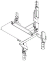
Referring to fig. 1, 11 and 12, these figures illustrate a die transfer device 400 according to some embodiments of the present disclosure. The small piece transfer device 400 is located on the side of the large piece breaking device 300 opposite to the large piece transfer device 200. The small piece transfer device 400 is used to feed the long glass pieces broken by the large piece breaking device 300 to the small piece breaking device 500 along the Y-axis direction.
The die transfer apparatus 400 generally includes a die glass holding mechanism, a second displacement mechanism, and a die holding base 414. The small glass holding mechanism may specifically be a vacuum suction type mechanism (hereinafter referred to as a small glass suction mechanism). The second displacement mechanism may include a die Y-axis drive mechanism, a die X-axis drive mechanism, and a die Z-axis drive mechanism.
The small piece Y-axis driving mechanism is used for enabling the small piece glass adsorption mechanism to move along the Y-axis direction. The small piece Y-axis driving mechanism comprises a small piece Y-axis motor 401, a small piece Y-axis nut connecting block 402, a small piece Y-axis nut rear seat 418, a small piece Y-axis screw rod assembly 419, a small piece Y-axis nut front seat 420, a small piece Y-axis motor seat 421 and a small piece Y-axis linear guide rail assembly 422. Wherein, the small piece Y-axis linear guide rail assembly 422, the small piece Y-axis nut rear seat 418, the small piece Y-axis nut front seat 420 and the small piece Y-axis motor seat 421 are fixedly arranged on the frame. The die Y-axis motor 401 is mounted on a die Y-axis motor mount 421. The small piece Y-axis moving plate 403 is installed on a sliding block of a small piece Y-axis linear guide rail assembly 422, and the sliding block is connected with a small piece Y-axis lead screw assembly 419 through a small piece Y-axis nut connecting block 402. The small piece Y-axis motor 401 drives the small piece Y-axis screw rod assembly 419 to rotate, and further the small piece Y-axis nut connecting block 402 is driven to drive the sliding block on the small piece Y-axis linear guide rail assembly 422 to synchronously move. Movement of the slider causes the die Y-axis moving plate 403 to move along the Y-axis.
The small piece X-axis driving mechanism is used for enabling the small piece glass adsorption mechanism to move along the X-axis direction. The small piece X-axis driving mechanism generally includes a small piece X-axis motor 407, a small piece X-axis motor base 408, a screw rod assembly (not shown in the figure), and a small piece X-axis linear guide assembly 423. A small piece X-axis motor mount 408 is fixed to the small piece Y-axis moving plate 403 and is used to fix the small piece X-axis motor 407. The small piece X-axis linear guide assembly 423 is fixed to the small piece Y-axis moving plate 403. A small piece X-axis moving plate 404 is mounted on the small piece X-axis linear guide assembly 423. Similar to the small piece Y-axis driving mechanism, the small piece X-axis motor 407 drives the screw rod assembly to rotate, thereby driving the small piece X-axis moving plate 404 to move along the small piece X-axis linear guide assembly 423.
And the small piece Z-axis driving mechanism is used for controlling the small piece glass adsorption mechanism to move along the Z-axis direction. The small piece Z-axis driving mechanism comprises a small piece Z-axis lead screw seat 405, a small piece Z-axis lead screw assembly 406, a small piece Z-axis motor seat 409, a small piece Z-axis motor 410 and a small piece Z-axis linear guide rail assembly 411. The small piece Z-axis lead screw seat 405, the small piece Z-axis motor seat 409 and the small piece Z-axis linear guide rail assembly 411 are fixed on the small piece X-axis moving plate 404, and the small piece Z-axis motor seat 409 is installed on the small piece Z-axis motor seat 409. The small piece Z-axis lifter plate 417 is mounted to the slide of the small piece Z-axis linear guide assembly 411. The working principle of the small piece Z-axis driving mechanism is similar to that of the small piece Y-axis driving mechanism, and the main difference is that the small piece Z-axis driving mechanism drives the small piece Z-axis lifting plate 417 to move up and down.
The chip suction mechanism is used for sucking the primarily broken long glass and feeding it into the chip breaking device 500. The die attach mechanism generally includes a die chuck securing screw 412, a die chuck securing block 413, a die chuck 415, and a die chuck securing lever 416. The die chuck fixing lever 416 is fixedly mounted on the die Z-axis elevating plate 417. At least one die suction cup 415 is mounted on the die suction cup mounting bar 416 by a die suction cup mounting screw 412 and a die suction cup mounting block 413. Die chuck 415 is mounted in a manner similar to that of vacuum chuck 209. The number and relative positions of the die pads 415 are determined by the length dimension and number of die glasses. The chip suction pad 415 is connected to a vacuum machine through a vacuum line to control the suction pad to suck and release the glass using the vacuum machine.
A die support base 414 is fixedly mounted to the frame. The chip support base 414 extends between the chip glass support mechanism and the chip Y-axis drive mechanism of the chip breaking apparatus 300 and has a height similar to the height of the support plate 208. A die holding base plate 414 is located below the die attach mechanism and is used to receive the glass released by the die attach mechanism.
A tab severing device 500 according to the present disclosure is illustrated with reference to fig. 1, 13-15. The small piece breaking device 500 is used to break the long glass strip in another scribing direction (generally in the X-axis direction) to be divided into a plurality of small pieces. The chip breaking device 500 is provided in front of the chip holding base 414 in the feeding direction (the direction indicated by the arrow in fig. 3).
The die severing device 500 generally includes a die support mechanism, a die severing mechanism, and an optional die feed mechanism.
The small piece supporting mechanism plays a role of supporting and supporting the glass. The small piece supporting mechanism comprises a small piece breaking-off rod 516 and two sets of small piece breaking-off rod supporting components for supporting two ends of the small piece breaking-off rod 516. The tab severing bar 516 extends generally in the X-axis direction. Two sets of small piece breaking bar supporting assemblies are respectively arranged at one side close to the large piece breaking device 300 and one side close to the small piece Y-axis moving plate 403. Each set of small broken rod supporting components comprises a lower actuator 512 and a broken rod supporting strip 513. The breaking bar support bars 513 are used to support the small-piece breaking bars 516. The lower actuator 512 can drive the breaking bar supporting bar 513 to move up and down. Optionally, each set of small breaking-off rod supporting assembly may further include a small scale display panel 511 and a small pointer 517, which are used for displaying the highest position of the small breaking-off rod 516, so as to facilitate adjustment of the position of the small breaking-off rod 516. The scale display panel 511 and the lower actuator 512 are directly fixed on the frame.
The small piece breaking mechanism swings downwards to apply breaking pressure to the glass so as to break the glass. The small piece breaking-off mechanism is arranged right above the small piece supporting mechanism. The small piece breaking-off mechanism mainly comprises small piece breaking-off strips 503 and two sets of small piece breaking-off strip mounting assemblies arranged at two ends of the small piece breaking-off strips 503. The small piece breaking-off bar 503 extends in the X-axis direction and is located right above the small piece breaking-off rod 516. Each set of small-piece breaking-off mounting assembly comprises a breaking-off connecting block 504, a small-piece breaking-off pressing wheel 505, a small-piece breaking-off pressing wheel seat 506, a small-piece breaking-off air cylinder 507, a guide wheel supporting plate 510 and two small-piece breaking-off guide wheels 518. The structure and action of the breaking-off bar coupling block 504 are similar to those of the breaking-off bar holder 301. One side of the breaking-off bar connecting block 504 is connected with the small-piece breaking-off bar 503, and the other side is provided with two small-piece breaking-off guide wheels 518. The guide wheel supporting plate 510 is provided with an arc groove H. The small piece breaking guide wheel 518 is installed in the arc groove H. The breaking-off bar connecting block 504 is also provided with a pinch roller groove G. The small piece breaking pinch roller 505 is installed in the pinch roller groove G. The pinch roller shafts of the small-piece snapping pinch rollers 505 are mounted on the corresponding small-piece snapping pinch roller bases 506. The piece breaking cylinder 507 includes a main body mounted on the corresponding guide wheel support plate 510 and an output end connected to the corresponding piece breaking press wheel base 506. The small breaking cylinder 507 drives the small breaking pressure wheel seat 506 to move downwards, so that the small breaking pressure wheel 505 drives the small breaking guide wheel 518 mounted on the breaking bar connecting block 504 to slide in the arc groove H, the breaking bar connecting block 504 swings downwards around the axis of the arc groove H, and the action mode of the breaking bar connecting block is similar to that of a large breaking mechanism. Optionally, each set of die break bar mounting assemblies may further include an upper actuator 509. The upper actuator 509 may be mounted on the frame. Specifically, the upper actuator 509 includes an upper actuator fixing section connected to the frame and an upper actuator raising and lowering section movable in the Z-axis direction with respect to the upper actuator fixing section. The bearing block 508 may have a pair of vertical portions mounted on the upper actuator lift portion of the corresponding upper actuator 509 and a lateral portion connecting the pair of vertical portions laterally, wherein the vertical portion of the bearing block 508 is fixedly connected with the idler support plate 510. The upper actuator 509 can drive the support base 508 and the guide wheel support plate 510 up and down to adjust the height of the die severing bar 503.
The small piece conveying mechanism is used for conveying the small pieces of glass broken by the small piece breaking mechanism to the next working procedure. The chip transport mechanism generally includes a belt pallet 501, a chip conveyor belt 502, a chip driven roller 514, a chip drive roller 515, and a motor. Both the die driven roller 514 and the die drive roller 515 extend in the X direction and are attached to the frame at both ends. A tab follower roller 514 is disposed adjacent to tab severing bar 516. The die drive rollers 515 are disposed at positions spaced apart by a predetermined distance in the die feeding direction. The belt pallet 501 is disposed between a die driven roller 514 and a die drive roller 515. The chip conveyor 502 is wound around two rollers. Where the chip drive roller 515 may be driven by a motor and the chip driven roller 514 rotated by the chip conveyor 502. The small piece conveyor 502 rolls in the Y-axis direction (as indicated by an arrow in fig. 13) with the rotation of the small piece driving roller 515 to convey the broken small pieces of glass to the next process. Alternatively, other forms of conveying mechanisms commonly used in the art may be devised by those skilled in the art in place of the rollers and belts.
Alternatively, as shown in fig. 14, the lower portion of the small piece breaking bar 503 has a plurality of elongated dust suction ports J, and the dust generated when the glass is broken is sucked in and discharged through the dust suction joint I.
The controller includes a processor and a memory. The memory stores information for controlling the actions of the motor and the suction mechanism. The processor executes instructions stored by the memory to effect the various movements desired. The controller may be a single controller that controls all of the motors and the suction mechanisms, or may be a plurality of controllers that control the respective motors and the suction mechanisms, respectively.
The workflow of the fully automatic film opening system according to the present disclosure is described below. The glass a is placed at the loading position shown in fig. 3, the glass scribe shape data is introduced into the controller, and the controller is started after confirming that the cutter head 116 is at the working home position. The controller gives an instruction to move the cutter head 116 to the marking starting position, then the cutter head lifting cylinder 110 descends with the cutter head cylinder 115 in sequence to press the cutter head 116 on the upper surface of the glass A, and the marking depth is controlled by the cutter head cylinder 115. If only the Y-axis scribing driving mechanism or the X-axis scribing driving mechanism works independently, only one straight line can be scribed, and the two mechanisms can scribe a curve by interpolation movement. The cutter head rotation driving mechanism functions to control the cutting direction of the scribing cutter of the cutter head 116 to be the same as the tangential direction of the drawn curve or straight line.
After the glass A is scribed, the large glass adsorption mechanism is lifted by the large lifting mechanism, and then the large glass adsorption mechanism is conveyed to the position right above the scribing area by the large transfer mechanism. Then a large glass adsorption mechanism is placed on the upper surface of the marked glass by a large lifting mechanism, and a vacuum machine is started to adsorb the glass. Then, the glass is lifted and transferred to the placing position corresponding to the breaking-off device 300, and the glass is placed on the glass pallet 208, and then the vacuum machine is turned off, and the glass adsorption mechanism is lifted. Subsequently, the large transfer mechanism moves a distance corresponding to the width of one small glass sheet in the direction of the scribing apparatus 100. Thereafter, the large glass suction mechanism drops again and the vacuum machine is started to suck and lift the glass to move a distance of a small glass width in a direction close to the large breaking device 300, at which time the line closest to the large breaking device 300 is right above the breaking bar 308, and then the glass is lowered and released. The large glass suction mechanism is raised again and moved inward (in a direction away from the large breaking-off device 300) by the width distance of a small piece of glass, at which time the breaking-off bars 309 are positioned directly above the wire and breaking-off rods 308. When the glass is broken, the glass support mechanism is at the lowest position, and at this time, the large piece transfer device 200 has conveyed the outermost long glass of the glass a to the upper position of the glass support mechanism, and the scribe mark should be right above the central axis of the breaking bar 308. Subsequently, the breaking-off rod actuator 306 pushes the breaking-off rod 308 to rise to slightly lift the glass a from below, and then the breaking-off cylinder 304 acts to drive the pressing wheel 302 to move downwards, so that the breaking-off bar seat 301 is forced to rotate around the central axis of the arc guide groove C by an angle. The rotation of the breaking-off bar holder 301 causes the breaking-off bars 309 to deflect, and the deflection motion causes one side of the breaking-off bars 309 to press against the glass, and since the lower surface of the glass has been supported by the breaking-off bars 308, the glass is broken along the scratches under pressure, thereby obtaining a long glass including a plurality of small pieces. After the outermost glass is broken off by the large-piece breaking device 300, the large-piece glass adsorption mechanism descends again to move the glass outward by the distance of one piece of glass, and the process is repeated until all the glass is broken off completely. The last piece of glass may be transferred by the suction mechanism directly onto the tab substrate 414. In addition, the operation frequency of the large piece breaking device 300 should match the operation of the small piece breaking device 500.
The long glass ribbon cut off by the large-piece cutting device 300 is placed on the small-piece base 414. And the small piece X-axis driving mechanism sends the small piece adsorption mechanism to the position above the broken long glass strip, and then the small piece Z-axis driving mechanism descends to attach the small piece suction cup 415 to the upper surface of the glass and starts a vacuum machine to adsorb the long glass strip. The die Z-axis drive mechanism then ascends. The X-axis drive mechanism for the pieces is reset and the glass strip is transferred to the breaking position for the pieces, and then the Z-axis drive mechanism for the pieces is lowered again to place the glass strip on the bottom plate 414 for the pieces and the vacuum is turned off. Then the small piece Z-axis driving mechanism drives the small piece adsorption mechanism to ascend again and move backwards (i.e. in the direction away from the small piece breaking-off device 500) by the distance of the length dimension of the small piece of glass under the action of the small piece Y-axis driving mechanism. Then the small piece Z-axis driving mechanism drives the small piece adsorption mechanism to descend again to adsorb the glass and ascend, and the small piece Y-axis driving mechanism moves forwards by the distance of the length size of the small piece of glass. Thereafter, the chip Z-axis drive mechanism again drives the chip pick-up mechanism down and drops the glass onto the chip floor 414. At this time, the foremost small glass pieces of the long glass strips enter the breaking station of the small glass piece breaking device 500. When the small pieces are broken, it is confirmed that the small piece transfer device 400 sends the foremost small piece of glass on the glass strip to the small piece breaking station and the breaking score line of the glass surface is located right above the central axis of the small piece breaking bar 516. Then, the small piece supporting mechanism starts to operate, and the small piece lower actuator 512 lifts the small piece breaking bar 516 via the small piece breaking bar supporting bar 513 to lift the glass from below. Next, the piece breaking mechanism is operated, and the piece upper actuator 509 moves down all the components mounted thereon to make the lower surface of the piece breaking bar 503 abut on the upper surface of the glass. And then a small piece breaking cylinder 507 is started to enable a small piece breaking bar 503 to generate deflection action to press and break the glass along the surface scribing line. And then the small piece supporting mechanism and the small piece breaking mechanism are reset completely. The crushed glass chips are just landed on the chip conveyor 502 of the chip conveyor and conveyed to the next process. And repeating the process of breaking off the small glass pieces until the whole glass piece is broken into small pieces. The last piece of glass can be transferred to the piece conveyor 502 using the piece transfer apparatus 400.
The preferred embodiments of the present disclosure are described in detail with reference to the accompanying drawings, however, the present disclosure is not limited to the specific details of the above embodiments, and various simple modifications may be made to the technical solution of the present disclosure within the technical idea of the present disclosure, and these simple modifications all belong to the protection scope of the present disclosure.
It should be noted that, in the foregoing embodiments, various features described in the above embodiments may be combined in any suitable manner, and in order to avoid unnecessary repetition, various combinations that are possible in the present disclosure are not described again.
In addition, any combination of various embodiments of the present disclosure may be made, and the same should be considered as the disclosure of the present disclosure, as long as it does not depart from the spirit of the present disclosure.
Claims (10)
1. A full-automatic film opening system is characterized by comprising:
the scribing device comprises a cutter and a scribing driving mechanism for driving the cutter to move, and the scribing driving mechanism drives the cutter to scribe along at least two directions;
a large-piece transfer device including a large-piece glass holding mechanism, a pallet, and a first shift mechanism, the pallet being located on a side of the scribing device, the large-piece glass holding mechanism being mounted on the first shift mechanism and being moved between an area above the scribing device and an area above the pallet by being driven by the first shift mechanism;
the large sheet breaking device is positioned on one side of the large sheet transferring device opposite to the scribing device, and the large sheet breaking device breaks glass along one of at least two scribing directions;
a small piece transfer device that is located on the opposite side of the large piece breaking-off device from the large piece transfer device, the small piece transfer device including a small piece glass holding mechanism, a small piece holding base plate that extends between the large piece breaking-off device and the second displacement mechanism, and a second displacement mechanism on which the small piece glass holding mechanism is mounted and that is driven by the second displacement mechanism to move in another direction perpendicular to the movement direction of the large piece glass holding mechanism; and
and the small piece breaking device is closely adjacent to one end of the small piece bearing bottom plate and extends from one side close to the large piece breaking device to one side close to the second displacement mechanism, and the small piece breaking device breaks the glass along the other direction of at least two scribing directions.
2. The system of claim 1, wherein the scribing driving mechanism comprises three sets of driving mechanisms for driving the cutter to move in three directions perpendicular to each other, each set of driving mechanism comprises a fixed portion and a sliding portion, the sliding portion is capable of being displaced relative to the fixed portion under the action of the actuator, the fixed portion of the second set of driving mechanism is mounted on the sliding portion of the first set of driving mechanism, the first set of driving mechanism drives the second set of driving mechanism to move in a first transverse direction, the fixed portion of the third set of driving mechanism is mounted on the sliding portion of the second set of driving mechanism, so as to drive the third set of driving mechanism to move in a second transverse direction perpendicular to the first transverse direction by using the second set of driving mechanism, the cutter is arranged on the sliding portion of the third set of driving mechanism, and the cutter is driven to move in a third vertical direction perpendicular to both the first transverse direction and the second transverse direction .
3. The system according to claim 1, characterized in that it comprises two sets of the following means: the large-piece transferring device, the large-piece breaking device, the small-piece transferring device and the small-piece breaking device are symmetrically arranged on two sides of the marking device.
4. The system of claim 1, wherein the breaking apparatus comprises a large glass support mechanism and a large glass breaking mechanism located above the large glass support mechanism with a gap therebetween for receiving glass, the large glass breaking mechanism being capable of swinging downward and breaking glass in one of at least two scoring directions.
5. The system of claim 4, wherein the tab breaking device comprises a tab support mechanism and a tab breaking mechanism located above the tab support mechanism, the tab breaking mechanism being swingable downward to break the glass in the other of the at least two scoring directions.
6. The system of claim 1, wherein the bulk glass holding mechanism comprises a plurality of vacuum cups arranged in an array on the same horizontal plane.
7. The system of claim 2, wherein the scoring drive mechanism further comprises a tool tip rotational drive mechanism for driving a tool tip in rotation about a vertical axis, the first set of drive mechanism, the second set of drive mechanism, the third set of drive mechanism, and the tool tip rotational drive mechanism operating in an interpolated motion controlled manner.
8. The system according to claim 4, wherein the bulk glass supporting mechanism comprises an elongated breaking bar and two sets of breaking bar supporting assemblies supporting the breaking bar at both ends of the breaking bar, and the bulk glass press-breaking mechanism comprises a breaking bar and breaking bar mounting assemblies at both ends of the breaking bar, the breaking bar mounting assemblies driving the breaking bar to rotate around an axis parallel to an axis of the breaking bar, and the breaking bar is parallel to the breaking bar.
9. The system according to claim 8, further comprising a frame, wherein the breaking-off bar supporting assembly is fixedly mounted on the frame and has a breaking-off bar actuator for driving the breaking-off bars to move upward, and the breaking-off bar mounting assembly is connected to the first shifting mechanism of the large sheet transfer device and moves synchronously with the large sheet glass holding mechanism.
10. The system of claim 9, wherein each set of the snap-off bar mounting assemblies comprises:
a support block having a guide groove;
the breaking-off cylinder is mounted on the supporting block;
the pinch roller seat is arranged below the breaking-off cylinder and can move up and down under the driving of the breaking-off cylinder;
the wheel shaft of the pinch roller is arranged on the pinch roller seat;
the device comprises a breaking-off strip seat, wherein one side of the breaking-off strip seat is connected with the breaking-off strip, the other side of the breaking-off strip seat is provided with a convex shaft of a guide wheel, one side of the breaking-off strip seat, which is provided with the convex shaft of the guide wheel, also comprises an open slot, and the press wheel is arranged in the open slot;
a guide wheel disposed in the guide groove of the support block to define a movement path of the guide wheel with the guide groove.
Priority Applications (1)
| Application Number | Priority Date | Filing Date | Title |
|---|---|---|---|
| CN202110992534.7A CN113683297B (en) | 2021-08-27 | 2021-08-27 | Full-automatic system of opening sheet |
Applications Claiming Priority (1)
| Application Number | Priority Date | Filing Date | Title |
|---|---|---|---|
| CN202110992534.7A CN113683297B (en) | 2021-08-27 | 2021-08-27 | Full-automatic system of opening sheet |
Publications (2)
| Publication Number | Publication Date |
|---|---|
| CN113683297A true CN113683297A (en) | 2021-11-23 |
| CN113683297B CN113683297B (en) | 2023-06-23 |
Family
ID=78583235
Family Applications (1)
| Application Number | Title | Priority Date | Filing Date |
|---|---|---|---|
| CN202110992534.7A Active CN113683297B (en) | 2021-08-27 | 2021-08-27 | Full-automatic system of opening sheet |
Country Status (1)
| Country | Link |
|---|---|
| CN (1) | CN113683297B (en) |
Cited By (2)
| Publication number | Priority date | Publication date | Assignee | Title |
|---|---|---|---|---|
| CN114163116A (en) * | 2021-12-08 | 2022-03-11 | 苏州精海激光智能科技有限公司 | Large-breadth glass laser cutting equipment |
| CN115432918A (en) * | 2022-08-31 | 2022-12-06 | 彩虹(合肥)液晶玻璃有限公司 | Break disconnected workstation off with fingers and thumb based on cutting of glass substrate |
Citations (8)
| Publication number | Priority date | Publication date | Assignee | Title |
|---|---|---|---|---|
| GB759358A (en) * | 1952-05-06 | 1956-10-17 | Asahi Garasu Kabushiki Kaisha | Apparatus for automatically cutting glass sheets |
| US20030127484A1 (en) * | 2001-12-14 | 2003-07-10 | Bernd Wirsam | Method and equipment to divide glass plates into cut pieces |
| CN101125730A (en) * | 2007-08-29 | 2008-02-20 | 郑书法 | Flat glass on-line severing machine |
| JP3170661U (en) * | 2011-07-14 | 2011-09-22 | 株式会社シライテック | Glass substrate processing equipment |
| CN105800925A (en) * | 2016-03-11 | 2016-07-27 | 东莞市银锐精密机械有限公司 | Full-automatic glass slitting assembly line |
| CN106865968A (en) * | 2017-03-17 | 2017-06-20 | 东莞奔迅汽车玻璃有限公司 | The automatic hacking equipment of glass |
| CN206624779U (en) * | 2017-03-30 | 2017-11-10 | 郑州旭飞光电科技有限公司 | Press plate mechanism and glass substrate rip cutting mechanism for glass substrate line |
| CN109437537A (en) * | 2018-12-11 | 2019-03-08 | 浙江旭恒甬鑫智能科技有限公司 | Glass substrate cutting machine |
-
2021
- 2021-08-27 CN CN202110992534.7A patent/CN113683297B/en active Active
Patent Citations (8)
| Publication number | Priority date | Publication date | Assignee | Title |
|---|---|---|---|---|
| GB759358A (en) * | 1952-05-06 | 1956-10-17 | Asahi Garasu Kabushiki Kaisha | Apparatus for automatically cutting glass sheets |
| US20030127484A1 (en) * | 2001-12-14 | 2003-07-10 | Bernd Wirsam | Method and equipment to divide glass plates into cut pieces |
| CN101125730A (en) * | 2007-08-29 | 2008-02-20 | 郑书法 | Flat glass on-line severing machine |
| JP3170661U (en) * | 2011-07-14 | 2011-09-22 | 株式会社シライテック | Glass substrate processing equipment |
| CN105800925A (en) * | 2016-03-11 | 2016-07-27 | 东莞市银锐精密机械有限公司 | Full-automatic glass slitting assembly line |
| CN106865968A (en) * | 2017-03-17 | 2017-06-20 | 东莞奔迅汽车玻璃有限公司 | The automatic hacking equipment of glass |
| CN206624779U (en) * | 2017-03-30 | 2017-11-10 | 郑州旭飞光电科技有限公司 | Press plate mechanism and glass substrate rip cutting mechanism for glass substrate line |
| CN109437537A (en) * | 2018-12-11 | 2019-03-08 | 浙江旭恒甬鑫智能科技有限公司 | Glass substrate cutting machine |
Cited By (2)
| Publication number | Priority date | Publication date | Assignee | Title |
|---|---|---|---|---|
| CN114163116A (en) * | 2021-12-08 | 2022-03-11 | 苏州精海激光智能科技有限公司 | Large-breadth glass laser cutting equipment |
| CN115432918A (en) * | 2022-08-31 | 2022-12-06 | 彩虹(合肥)液晶玻璃有限公司 | Break disconnected workstation off with fingers and thumb based on cutting of glass substrate |
Also Published As
| Publication number | Publication date |
|---|---|
| CN113683297B (en) | 2023-06-23 |
Similar Documents
| Publication | Publication Date | Title |
|---|---|---|
| JP5434014B2 (en) | Glass plate processing method and glass plate processing apparatus | |
| CN113683297B (en) | Full-automatic system of opening sheet | |
| WO2015129252A1 (en) | Method and apparatus for processing glass sheet | |
| JP2020040877A (en) | Glass plate processing apparatus | |
| CN104766821A (en) | Cell splitting device and cell splitting method | |
| KR101991267B1 (en) | Apparatus for cutting substrate | |
| JP6195008B2 (en) | Glass plate processing equipment | |
| JP4149750B2 (en) | Glass plate processing equipment | |
| CN115057271A (en) | Smart card anti-overlapping feeding device and smart card production equipment | |
| JP3184284B2 (en) | Glass plate feeder | |
| KR101735040B1 (en) | Device to support glass plate | |
| CN216099249U (en) | Circuit board cutting machine | |
| CN114132751B (en) | Automatic separation device and separation method for tray | |
| CN113540923B (en) | Terminal cutting and breaking-off integrated machine for swing disc | |
| CN215433736U (en) | Battery piece suction mechanism, battery piece carrying device and series welding machine | |
| CN107601131A (en) | A kind of new storage paper conveyer and storage paper paper conveying method | |
| KR102328420B1 (en) | Support device for brittle substrate scribing process | |
| KR20190059577A (en) | Apparatus for cutting substrate | |
| JP5776830B2 (en) | Glass plate processing method and glass plate processing apparatus | |
| WO2015136946A1 (en) | Glass plate processing method and processing device | |
| CN105293039B (en) | Substrate transfer device | |
| JP3317280B2 (en) | Alignment transfer system for substrate and alignment transfer method | |
| JP6708825B2 (en) | Glass plate processing equipment | |
| CN216072110U (en) | Glass sheet unloading inserted sheet loading line | |
| CN112620911B (en) | Resistance welding equipment |
Legal Events
| Date | Code | Title | Description |
|---|---|---|---|
| PB01 | Publication | ||
| PB01 | Publication | ||
| SE01 | Entry into force of request for substantive examination | ||
| SE01 | Entry into force of request for substantive examination | ||
| GR01 | Patent grant | ||
| GR01 | Patent grant |