Waste box separation structure for box-contained diaphragm stripping device
Technical Field
The invention relates to the technical field of diaphragm cutting equipment, in particular to a waste box separating structure for a diaphragm stripping device with a box.
Background
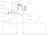
Many packaging bottles are packaged closed by a septum prior to filling with liquid or solid contents. As shown in fig. 1, a fixed number of bottle bodies 1 are completely packed in a package 2 having an open top, and the package 2 is closed at the outside and the top by a diaphragm 3. Before using the bottle 1 on a full stop line, it is necessary to peel off the package 2 and the diaphragm 3.
In the prior art, a cassette separator peeling apparatus shown in fig. 2 is used to separate a bottle body 1, a separator 3, and a packing box 2. The material will be packed and placed on pan feeding platform 4, material passageway 10 sets up in pan feeding platform 4, between ejection of compact platform 5, entry propelling movement structure 11, material turnover structure 9, material corner pay-off structure 8, two side belts connect material structure 7, material sharp propelling movement structure 6 with the material along material passageway 10 propelling movement to cut on the station of membrane structure 12, cut the membrane end back, the diaphragm waste material that is cut off in 1 bottom of bottle remains on cutting the station of membrane structure 12, bottle 1 and the packing carton 2 at top, diaphragm 3 need send into next station and separate. However, the existing tape cassette separator peeling device can only manually separate the waste tape cassette by workers, which is not only inefficient, but also costly.
Disclosure of Invention
In order to solve the problems that the efficiency of a separation process is low and the cost is high due to the fact that workers are required to completely and manually separate a packaging box, a diaphragm and a bottle body in the existing tape box diaphragm stripping device, the invention provides a waste box separation structure for the tape box diaphragm stripping device, the workers are not required to manually separate the packaging box, the bottle body and the diaphragm, the overall process efficiency is improved, and the system cost is reduced.
The technical scheme of the invention is as follows: the utility model provides a take box diaphragm stripping off device with useless box separation structure which characterized in that, it includes: the waste box clamping structure, the waste box lifting structure and the waste box horizontal moving structure are arranged on the waste box separating bracket; the waste box lifting structure drives the waste box clamping structure to perform lifting motion in the vertical direction, and the waste box horizontal moving structure drives the waste box lifting structure to perform parallel movement in the horizontal direction;
useless box clamping structure includes: the waste box clamping plates are arranged in pairs, are respectively arranged at the piston ends of the waste box clamping cylinders and horizontally move in opposite directions;
the waste box lifting structure comprises a box taking lifting cylinder, the piston end of the box taking lifting cylinder is vertically arranged downwards, and the waste box clamping structure is fixedly connected with the piston end of the box taking lifting cylinder;
the waste box horizontal moving structure comprises a waste box horizontal moving linear module, wherein the waste box horizontal moving linear module is arranged above a station of a waste box separating structure, the waste box lifting structure is arranged on a horizontal moving sliding seat of the waste box horizontal moving linear module, and the horizontal moving sliding seat moves above the station of the waste box separating structure and a waste box.
It is further characterized in that:
the waste box horizontal moving mechanism further comprises a shaking structure, wherein the shaking structure comprises a shaking cylinder, the shaking cylinder is arranged on the horizontal moving sliding seat of the waste box horizontal moving linear module, and the waste box lifting structure is connected to a piston rod of the shaking cylinder;
a piston rod of the shaking cylinder is horizontally arranged, and the waste box lifting structure is driven by the shaking cylinder to move in the horizontal direction;
the bottom end of the horizontal moving sliding seat is connected with the horizontal moving guide rail in a sliding manner through a sliding block and sliding rail structure;
the waste box lifting structure is fixedly connected with one end of a horizontal connecting plate, and the other end of the horizontal connecting plate is connected with the piston end of the shaking cylinder; the bottom end of the horizontal connecting plate is connected with the guide rail for shaking in a sliding mode through a sliding block sliding rail structure.
According to the waste box separation structure for the film stripping device with the box, the packaging box at the top of the bottle body is clamped from two sides through the waste box clamping plates, the waste box lifting structure drives the packaging box and the diaphragm sleeved outside the packaging box to lift, the waste box horizontal moving structure drives the packaging box and the diaphragm to horizontally move to the upper part of the waste box, the waste box clamping plates loosen clamping on the packaging box from two sides, the packaging box and the diaphragm fall into the waste box, and separation operation of the bottle body, the packaging box and the diaphragm in pair is carried out; in the whole separation process, workers do not need to manually perform separation operation, so that the efficiency of the separation process is improved, and the cost of the whole system is reduced.
Drawings
FIG. 1 is a schematic structural view showing the structural relationship among a diaphragm, a packing box and a bottle body;
fig. 2 is a schematic structural view of a prior art separator for a tape cassette;
FIG. 3 is a schematic view of the overall structure of the waste box separating structure in a front view;
FIG. 4 is a schematic top view of the waste box separating structure according to the present invention;
fig. 5 is a schematic view showing the overall structure of a tape cassette separator peeling apparatus to which the waste cassette separating structure of the present invention is attached.
Detailed Description
As shown in fig. 3 to 5, the waste box separating structure for a separating device of a separating film with a box of the present invention includes: a waste box clamping structure, a waste box lifting structure and a waste box horizontal moving structure which are arranged on the waste box separation bracket 13-12; the waste box lifting structure drives the waste box clamping structure to perform lifting motion in the vertical direction, and the waste box horizontal moving structure drives the waste box lifting structure to perform parallel movement in the horizontal direction.
The material linear pushing structure 6 pushes the material to the station of the film cutting structure 12 along the material channel 10, after the film cutting is finished, the membrane waste materials cut from the bottom of the bottle body 1 are remained on the station of the film cutting structure 12, and the bottle body 1 and the packing box 2 and the membrane 3 at the top of the bottle body are sent to the station of the waste box separating structure 13.
Useless box clamping structure includes: the waste box clamping plates 13-1, the waste box clamping plates 13-1 appear in pairs, are respectively arranged at the piston ends of the waste box clamping cylinders 13-2 and move horizontally in opposite directions; the waste box clamping structure comprises 1 pair of waste box clamping plates 13-1 and a waste box clamping cylinder 13-2, wherein the waste box clamping cylinder 13-2 is fixed on the bottom end face of a lifting connecting plate 13-6, and the two waste box clamping plates 13-1 are symmetrically arranged on the bottom end face of the lifting connecting plate 13-6; the bottom end face of the lifting connecting plate 13-6 is respectively provided with two sliding rails 13-3 for clamping along the movement direction of the piston of the waste box clamping cylinder 13-2, the top end faces of the two waste box clamping plates 13-1 are respectively connected with the sliding rails 13-3 for clamping in a sliding mode through sliding rail and sliding block structures, and the two waste box clamping plates 13-1 can stably move in the horizontal direction through the sliding rails 13-3 for clamping; the farthest distance of the stroke between the two waste box holding plates 13-1 is larger than the width between the two held side walls of the packing box 2, ensuring that the two waste box holding plates 13-1 can hold the side walls of the two sides of the packing box 2 from both sides. The vertical default position of the waste box clamping plates 13-1 is right above the station of the waste box separation structure, the height of the materials entering the station of the waste box separation structure cannot be influenced, and the default distance between the two waste box clamping plates 13-1 is the maximum separation distance.
The waste box lifting structure comprises a box taking lifting cylinder 13-5, the piston end of the box taking lifting cylinder 13-5 is vertically arranged downwards, and the piston end of the box taking lifting cylinder 13-5 is fixedly connected with the top end face of a lifting connecting plate 13-6 to drive the waste box clamping structure to perform lifting movement.
The waste box horizontal moving structure is arranged at the top end of the waste box separating bracket 13-12 and comprises a waste box horizontal moving linear module 13-4, the waste box horizontal moving linear module 13-4 is arranged above a station of the waste box separating structure, a waste box lifting structure is arranged on a horizontal moving sliding seat 13-10 of the waste box horizontal moving linear module 13-4, and the horizontal moving sliding seat 13-10 moves above the station of the waste box separating structure and a waste box 14. The linear module 13-4 is implemented based on a device capable of implementing linear driving in the prior art, such as a module based on a synchronous belt type, a ball screw type, a linear motor type, or an air cylinder, and the linear module in this embodiment is implemented based on a linear module driven by a servo motor. The linear module 13-4 drives the waste box clamping structure, the clamped packaging box 2 and the diaphragm 3 to move between the station of the waste box separating structure and the waste box 14 through the horizontal moving sliding seat 13-10, so that the packaging box 2 is clamped, and the packaging box 2 and the diaphragm 3 are placed in the waste box 14.
The bottom end of the horizontal moving sliding seat 13-10 is provided with a horizontal moving guide rail 13-11, the horizontal moving guide rail 13-11 is arranged in parallel with the motion direction of the horizontal moving sliding seat 13-10 of the linear module 13-4, the bottom end of the horizontal moving sliding seat 13-10 is connected with the horizontal moving guide rail 13-11 in a sliding mode through a sliding block and sliding rail structure, and the horizontal moving sliding seat 13-10 is supported through the horizontal moving guide rail 13-11 in the process that the horizontal moving sliding seat 13-10 drives the waste box clamping structure to move horizontally, so that stable movement is achieved.
The waste box separation structure also comprises a shaking structure, and the shaking structure comprises: the shaking cylinder 13-7, the shaking cylinder 13-7 is arranged on a horizontal moving sliding seat 13-10 of the waste box horizontal moving linear module 13-4, and the waste box lifting structure is connected to a piston rod of the shaking cylinder 13-7; a piston rod of a shaking cylinder 13-7 is horizontally arranged, and a waste box lifting structure is driven by the shaking cylinder 13-7 to move in the horizontal direction; the shaking guide rail 13-8 is parallel to the moving direction of a piston rod of the shaking cylinder 13-7 and is arranged on the upper end surface of the horizontal moving sliding seat 13-10, the waste box lifting structure is fixedly connected with one end of a horizontal connecting plate 13-9, and the other end of the horizontal connecting plate 13-9 is connected with the piston end of the shaking cylinder 13-7; the bottom end of the horizontal connecting plate 13-9 is connected with a shaking guide rail 13-8 in a sliding manner through a slide block and slide rail structure. After the shaking air cylinder 13-7 is started, the waste box lifting structure is driven by the horizontal connecting plate to move in the horizontal direction, and the shaking guide rail 13-8 supports the horizontal connecting plate 13-9 to stably slide on the upper end face of the horizontal moving sliding seat 13-10, so that the integral balance in the sliding process is ensured.
Based on the technical scheme of the invention, when the separation operation of the packaging box 2 and the bottle body 1 is required, the box taking lifting cylinder 13-5 is started to drive the waste box clamping plate 13-1 to descend to the outer sides of the top ends of the two side walls of the packaging box 2 from the default position, the two waste box clamping cylinders 13-2 are started to drive the two waste box clamping plates 13-1 to clamp the top ends of the two opposite side walls of the packaging box 2 from the two sides and then stop; the shaking cylinder 13-7 is started to drive the waste box lifting structure, the packaging box 2 and the diaphragm 3 to slide along the shaking guide rail 13-8 in the horizontal direction for a short distance, and then the shaking cylinder 13-7 is started reversely to drive the waste box lifting structure, the packaging box 2 and the diaphragm 3 to slide reversely along the shaking guide rail 13-8 in the horizontal direction for a very short distance, so that the shaking effect on the packaging box 2 and the diaphragm 3 is realized through repeated short-distance horizontal sliding for several times in a short time, the diaphragm 3 and the packaging box 2 are separated from the bottle body 1 packaged in the packaging box, and the diaphragm 3 and the packaging box 2 are prevented from driving the bottle body 1 to lift simultaneously due to friction force in subsequent lifting movement; the repeated horizontal movement times of the specific shaking air cylinders 13-7 are set according to the material and the weight of the bottle body 1; after shaking is finished, the box taking lifting cylinder 13-5 is started reversely to drive the packing box 2 to rise to a default height position and then stop; the linear module 13-4 is started, and the horizontally moving sliding seat 13-10 drives the clamped diaphragm 3 and the packing box 2 to horizontally move until the diaphragms move to the position above the opening of the waste box 14 and then stop moving; the two waste box clamping cylinders 13-2 are started to be started reversely, the two waste box clamping plates 13-1 are driven to move to the two sides to the default positions and then stop, and the packaging box 2 and the diaphragm 3 are loosened and fall into the waste box 14; starting the linear module 13-4 in a reverse direction to drive the two waste box clamping plates 13-1 to return to default positions, and finishing the waste box separating operation; the bottle bodies 1 at the station of the waste box separating structure 13 are conveyed to the discharging platform 5.