CN113668849A - Post-cast strip pouring equipment and construction method thereof - Google Patents
Post-cast strip pouring equipment and construction method thereof Download PDFInfo
- Publication number
- CN113668849A CN113668849A CN202110976300.3A CN202110976300A CN113668849A CN 113668849 A CN113668849 A CN 113668849A CN 202110976300 A CN202110976300 A CN 202110976300A CN 113668849 A CN113668849 A CN 113668849A
- Authority
- CN
- China
- Prior art keywords
- back edge
- post
- template
- hoisting
- plate
- Prior art date
- Legal status (The legal status is an assumption and is not a legal conclusion. Google has not performed a legal analysis and makes no representation as to the accuracy of the status listed.)
- Pending
Links
Images


Classifications
-
- E—FIXED CONSTRUCTIONS
- E04—BUILDING
- E04G—SCAFFOLDING; FORMS; SHUTTERING; BUILDING IMPLEMENTS OR AIDS, OR THEIR USE; HANDLING BUILDING MATERIALS ON THE SITE; REPAIRING, BREAKING-UP OR OTHER WORK ON EXISTING BUILDINGS
- E04G13/00—Falsework, forms, or shutterings for particular parts of buildings, e.g. stairs, steps, cornices, balconies foundations, sills
-
- E—FIXED CONSTRUCTIONS
- E04—BUILDING
- E04G—SCAFFOLDING; FORMS; SHUTTERING; BUILDING IMPLEMENTS OR AIDS, OR THEIR USE; HANDLING BUILDING MATERIALS ON THE SITE; REPAIRING, BREAKING-UP OR OTHER WORK ON EXISTING BUILDINGS
- E04G17/00—Connecting or other auxiliary members for forms, falsework structures, or shutterings
- E04G17/001—Corner fastening or connecting means for forming or stiffening elements
Abstract
The invention provides post-cast strip pouring equipment and a construction method thereof, wherein the post-cast strip pouring equipment comprises a movable hoisting trolley and a hoisting template assembly, the movable hoisting trolley comprises a trolley body, a slider, an electric winch and a screw connector, the electric winch is arranged on the trolley body through the slider, and the end part of a steel wire rope of the electric winch is connected with the screw connector; the hoisting assembly template comprises a plate bottom hoisting assembly template and a beam bottom hoisting assembly template; the uppermost ends of the screws in the hoisting template assembly are connected through screw connectors, so that the hoisting template assembly is hoisted to the bottom of the post-cast strip by using a hoisting trolley; and (4) performing concrete pouring on the post-cast strip after the template assembly is hoisted, and dismantling and recycling the beam bottom hoisting template assembly after the dismantling condition is met. The invention carries out template combination deepening on the construction area of the post-cast strip, reduces the trouble of on-site assembly, improves the construction efficiency, can repeatedly use equipment with the same structure and avoids secondary disassembly and assembly.
Description
Technical Field
The invention belongs to the field of building construction, and particularly relates to post-cast strip pouring equipment and a construction method thereof.
Background
Along with the rapid development of the construction industry, super high-rise and deep foundation pit buildings are more and more, the set volume of the post-cast strip of the underground structure is increased, and the post-cast strip is more and more frequently deposited, temperature post-cast strip and shrinkage post-cast strip in construction, so that the problems of large casting volume, difficult casting and the like at the post-cast strip are increasingly highlighted. Particularly, in the post-cast strip located in the basement, the transportation, erection and concrete pouring of the construction materials are very difficult.
In view of the above problems, it is important to have a more efficient apparatus and a construction method thereof.
Disclosure of Invention
Aiming at the problems in the prior art, the invention aims to provide post-cast strip pouring equipment and a construction method thereof.
The purpose of the invention is realized by the following technical scheme:
a post-cast strip pouring device comprises a movable hoisting trolley and a hoisting template assembly, wherein the movable hoisting trolley comprises a trolley body, a slider, an electric winch and a screw connector, the electric winch is installed on the trolley body through the slider, and the end of a steel wire rope of the electric winch is connected with the screw connector;
the hoisting assembly template comprises a plate bottom hoisting assembly template and a beam bottom hoisting assembly template;
the plate bottom hoisting template assembly comprises a screw, a plate top back edge, a template, a plate bottom longitudinal back edge and a plate bottom transverse back edge, a hole is formed in the middle of the template and used for the screw to penetrate through, the plate top back edge, the template, the plate bottom longitudinal back edge and the plate bottom transverse back edge are all installed on the screw, the plate top back edge is located at the upper part of the post-cast strip structure and perpendicular to the post-cast strip direction, the template, the plate bottom longitudinal back edge and the plate bottom transverse back edge are located at the lower part of the post-cast strip structure, and the template and the plate bottom longitudinal back edge are perpendicular to the post-cast strip direction, and the plate bottom transverse back edge is parallel to the post-cast strip direction;
the beam bottom hoisting template assembly comprises a screw, three plate top back ridges, a template, two plate bottom longitudinal back ridges, six L-shaped back ridges, three beam bottom transverse back ridges and one beam bottom longitudinal back ridge, a hole is formed in the middle of the template and used for the screw to pass through, the plate top back ridges, the beam bottom transverse back ridges and the beam bottom longitudinal back ridges are all installed on the screw, the plate top back ridges are located at the upper part of the post-pouring belt structure, other back ridges are located at the lower part of the post-pouring belt structure, the beam bottom transverse back ridges are parallel to the post-pouring belt direction, and the plate bottom longitudinal back ridges and the beam bottom longitudinal back ridges are perpendicular to the post-pouring belt direction; the non-hole end of the L-shaped back edge and the longitudinal back edge of the plate bottom are connected with the template and the plate top back edge through screws, the lower end of the L-shaped back edge is perforated, the two ends of the transverse back edge of the beam bottom are perforated, and the L-shaped back edge and the longitudinal back edge of the plate bottom are connected through short bolts; the beam bottom transverse back edge and the beam bottom longitudinal back edge are connected with the plate top back edge through screws;
and the uppermost ends of the screws in the hoisting template assemblies are connected through screw connectors, so that the hoisting template assemblies are hoisted to the bottom of the post-cast strip by utilizing the hoisting trolley.
Furthermore, the screw connector comprises an upper convex concave type threaded sleeve, a concave type opening sleeve and a non-threaded screw rod, the upper portion of the non-threaded screw rod penetrates through the opening of the concave type opening sleeve and is connected with a steel wire rope on the electric winch, and the upper convex thread of the upper convex concave type threaded sleeve is connected with the concave type opening sleeve and is screwed down.
Furthermore, the cross section of the plate top back edge is U-shaped.
Further, the bottom of the trolley body is provided with a movable wheel.
Furthermore, each back edge in the equipment is a double-square steel back edge and is fixed on the screw rod through a gasket and a nut.
Further, the diameter of a hole in the right middle of the template is larger than the diameter of the screw and the diameter of the screw connector.
Further, the plate bottom hoisting template assembly comprises at least three plate bottom longitudinal back edges and three plate bottom transverse back edges, the plate bottom transverse back edges positioned in the middle are connected with the plate bottom longitudinal back edges through screws, and the two plate bottom transverse back edges with separation blades used for fixing the two sides are welded at the two ends of the plate bottom longitudinal back edges.
Furthermore, the template in the beam bottom hoisting template assembly comprises a plate bottom template, beam side templates and a beam bottom template, wherein the plate and the beam internal corners are connected with the bottom template and the beam side templates through C-shaped grooves, and the angle aluminum is connected with the beam side templates and the beam bottom template.
Another aspect of the invention:
a pouring construction method for a closed post-cast strip comprises the following steps:
firstly, selecting a plate top back edge, a template, a plate bottom longitudinal back edge and a plate bottom transverse back edge which are suitable for the sizes according to the pouring size of a plate bottom post-pouring belt;
then, assembling the plate bottom hoisting template assembly, enabling a screw to penetrate through a hole in the center of the template and fix the hole, vertically overlapping the plate bottom longitudinal back edge and the plate bottom transverse back edge below the template, and fixing the plate bottom longitudinal back edge and the plate bottom transverse back edge in the middle through the screw, upper and lower mounting gaskets and nuts, so that the plate bottom hoisting template assembly except the plate top back edge is formed in an overlapping manner;
thirdly, placing the assembled template assembly for hoisting at the bottom of the plate except the top and the back of the plate on the lower structural surface of the post-construction casting belt, hoisting the template assembly by using a movable hoisting trolley, connecting a screw connector with a screw, adjusting the position of the template assembly by using a slider to enable the template assembly to be positioned at the corresponding position of the post-construction casting belt, and starting an electric winch to hoist the template assembly to the bottom of the post-construction casting belt; reinforcing the screw rod in the middle, firstly installing a sleeve, then installing the plate top back ridges on the screw rod in the middle, and then respectively installing the plate top back ridges on the two sides;
and fourthly, pouring concrete into the post-pouring belt after the template assembly is hoisted, and dismantling and recycling the plate bottom hoisting template assembly after the dismantling condition is met.
A pouring construction method for a post-cast strip at a beam bottom comprises the following steps:
firstly, selecting a plate top back edge, a template, a plate bottom longitudinal back edge, an L-shaped back edge, a beam bottom transverse back edge and a beam bottom longitudinal back edge which are suitable for the sizes according to the pouring size of a post-pouring strip beam;
then, assembling the beam bottom hoisting template assembly, connecting the bottom die and the beam side die at the internal corners of the plate and the beam by using a C-shaped groove, connecting the beam side die and the beam bottom die by using angle aluminum, punching at the lower end of the L-shaped back edge, punching at two ends of the transverse back edge of the beam bottom, and connecting the two through short bolts according to the size of the beam; the L-shaped back edge and the beam bottom lotus-flavor back edge are respectively connected with the plate bottom die and the beam bottom die through screws, and the two longitudinal back edges of the plate bottom and the longitudinal back edge of the beam bottom are respectively arranged at the non-porous end of the L-shaped back edge and the lower part of the transverse back edge of the beam bottom and are fixed on the screws, so that the beam bottom hoisting template assembly except the plate top back edge is formed in a lap joint manner;
thirdly, placing the beam bottom hoisting template assembly assembled in the previous step except the plate top and back edges on the lower structural surface of the post-construction casting belt, hoisting the beam bottom hoisting template assembly by using a movable hoisting trolley, connecting a screw connector with a screw, adjusting the position of the beam bottom hoisting template by using a slider to enable the beam bottom hoisting template assembly to be positioned at the corresponding position of the post-construction casting belt, and starting an electric winch to hoist the template assembly to the bottom of the post-construction casting belt; reinforcing a middle screw rod arranged on a beam bottom back edge, firstly installing a sleeve, then installing a plate top back edge on the middle screw rod, arranging two ends of the plate top back edge on the tops of two side plates of a post-cast strip, repeating the installation process after the reinforcing is finished, and then respectively reinforcing the screw rods arranged on the two L-shaped back edges;
and fourthly, pouring concrete into the post-cast strip after the template assembly is hoisted, and dismantling and recycling the beam bottom hoisting template assembly after the dismantling condition is met.
Compared with the prior art, the invention has the beneficial effects that:
1. according to the invention, template combination deepening is carried out on a post-cast strip construction area, the trouble of field assembly is reduced, template assembly and combination construction is preferentially used, and a wood template is used for a special position; the construction efficiency can be greatly improved, and the post-cast strip pouring equipment can be repeatedly used for the same structure, so that secondary disassembly and assembly are avoided;
2. in the post-cast strip pouring equipment, the template and other various materials can be used for multiple times, the material turnover rate is high, the loss is small, the template can be transferred to other projects after the project is finished, the material cost is greatly saved, and the material transportation is more convenient than that of the traditional construction method.
Drawings
The invention is further illustrated by the following examples in conjunction with the accompanying drawings:
FIG. 1 is a schematic structural diagram of a plate bottom post-cast strip pouring device in embodiment 1;
FIG. 2 is a schematic structural view of the screw connector;
FIG. 3 is a schematic view of the construction of a slab bottom post-cast strip pouring hoisting assembly in example 1;
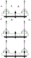
FIG. 4 is a schematic structural diagram of the beam bottom post-cast strip casting equipment in embodiment 2;
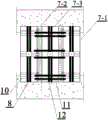
FIG. 5 is a bottom view of FIG. 4;
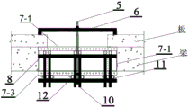
FIG. 6 is a side view of FIG. 4;
in the figure:
a trolley body (1); a slider (2); an electric winch (3); the device comprises a screw connector (4), an upper convex and lower concave threaded sleeve (4-1), a concave hole-opening sleeve (4-2) and a non-threaded screw (4-3); a screw (5); a plate top back edge (6); the template (7), the template bottom die (7-1), the beam side die (7-2) and the beam bottom die (7-3); the longitudinal back edge (8) of the plate bottom; a transverse back edge (9) of the plate bottom; an L-shaped back edge (10); a beam bottom transverse back edge (11); a bottom longitudinal back edge (12); a baffle plate (13); a C tank (14); an angle aluminum (15); a gasket (16); a nut (17).
Detailed Description
The technical solution of the present patent will be described in further detail with reference to the following embodiments.
Reference will now be made in detail to embodiments of the present patent, examples of which are illustrated in the accompanying drawings, wherein like or similar reference numerals refer to the same or similar elements or elements having the same or similar function throughout. The embodiments described below with reference to the drawings are exemplary only for the purpose of explaining the present patent and are not to be construed as limiting the present patent.
Example 1
As shown in fig. 1, the embodiment provides a slab bottom post-cast strip casting equipment, which comprises a movable hoisting trolley and a slab bottom hoisting template assembly, wherein the movable hoisting trolley comprises a trolley body 1, a slider 2, an electric winch 3 and a screw connector 4, the electric winch is installed on the trolley body through the slider, and the end of a steel wire rope of the electric winch is connected with the screw connector.
Hoist and mount template subassembly includes screw rod 5, the stupefied 6 of board top back of the body, aluminum alloy template 7, the stupefied 8 of board bottom longitudinal back of the body and the stupefied 9 of board bottom transverse back of the body, open a hole in the middle of aluminum alloy template 7 is positive, and the diameter is greater than the diameter of screw rod 5 diameter and screw connector 4 for the screw rod passes, and the stupefied 6 of board top back of the body, template 7, the stupefied 8 of board bottom longitudinal back of the body and the stupefied 9 of board bottom transverse back of the body are all installed on screw rod 5, and the stupefied upper portion that 6 of board top back of the body is located post-cast strip structure and perpendicular to post-cast strip direction, and the stupefied lower portion that 8 of board bottom longitudinal back of the body and board bottom transverse back of the body are located post-cast strip structure, and the stupefied direction of board bottom longitudinal back of the body perpendicular to post-cast strip direction, and the stupefied direction of board bottom transverse back of the body is parallel to post-cast strip direction.
As shown in fig. 2, the screw connector 4 is composed of an upper convex and lower concave type threaded sleeve 4-1, a concave type opening sleeve 4-2 and a non-threaded screw 4-3, the upper part of the non-threaded screw passes through the opening of the concave type opening sleeve and is connected with a steel wire rope on the electric winch 3, and the upper convex thread of the upper convex and lower concave type threaded sleeve is connected with the concave type opening sleeve and is screwed tightly; the upper convex concave type threaded sleeve 4-1 at the lowermost end is connected with the uppermost end of a screw rod 5 in the plate bottom hoisting template assembly, so that the plate bottom hoisting template assembly is hoisted to the bottom of the post-cast strip by using a hoisting trolley.
In this embodiment the back of the body is stupefied to the both sides steel back of the body, the stupefied 8 of the vertical back of the body of board and the stupefied 9 nodical position department of the horizontal back of the body of board are from supreme order down: the screw rod 5, the gasket 16, the longitudinal back edge 8 of the plate bottom, the transverse back edge 9 of the plate bottom, the gasket 16, the nut 17 and the aluminum alloy template 7 are fixed through the screw rod, the gasket and the nut. The number of the transverse back edges 9 of the plate bottom is three, one is positioned in the middle, and the other two are positioned at two ends. And the two ends of the longitudinal back edge 8 of the plate bottom are welded with the blocking pieces 13 for fixing the transverse back edges of the plate bottom on the two sides.
The length and the size of the aluminum alloy template 7 are fixed, the same length is adopted, the width is of various types, the length is increased to 400mm from 100mm one by taking 50mm as a unit, the length required by pouring of the assembled post-cast strip is longer, and the aluminum alloy templates with different sizes are reasonably used according to the pouring length.
As shown in fig. 3, a specific method for performing slab bottom post-cast strip casting construction by applying the slab bottom post-cast strip casting device in this embodiment is as follows:
firstly, at least three aluminum alloy templates 7 form a hoisting group and at least three screws 5 are used, the number of the plate bottom transverse back ridges 9 of each group is three, the number of the plate bottom longitudinal back ridges 8 is the same as that of the screws 5, the plate bottom transverse back ridges 9 are determined according to the size of a post-cast strip to be poured and are telescopic back ridges, the height difference exists between the stretched back ridges and the original back ridges, and the plate bottom longitudinal back ridges 8 are the same as the aluminum alloy templates 7 in length through leveling gaskets.
Then, assembling a plate bottom hoisting template assembly, enabling a screw to penetrate through a hole in the center of a template and be fixed, vertically overlapping a plate bottom longitudinal back edge 8 and a plate bottom transverse back edge 9 below the template, fixing the plate bottom longitudinal back edge 8 and a plate bottom transverse back edge 9 in the middle through the screw 5, and vertically installing a gasket and a nut so as to overlap and form the plate bottom hoisting template assembly except a plate top back edge 6;
thirdly, placing the assembled template assembly for hoisting at the bottom of the plate except the top and the back of the plate on the lower structural surface of the post-construction casting belt, hoisting the template assembly by using a movable hoisting trolley, connecting a screw connector with a screw, adjusting the position of the template assembly by using a slider to enable the template assembly to be positioned at the corresponding position of the post-construction casting belt, and starting an electric winch to hoist the template assembly to the bottom of the post-construction casting belt; reinforcing the screw rod in the middle, firstly installing a sleeve, and then installing a plate top back ridge on the middle screw rod to finish the hoisting of a group of template components; loosening the screw connector 4 at one end after the middle part is reinforced, repeating the installation process, hoisting another group of template components, loosening the screw connector 4 after the middle part is reinforced, repeating the installation process again until the hoisting assembly required by the post-cast strip which needs to be poured at one end is completed;
fourthly, plugging two ends of a post-cast strip to be poured by using a wire netting, pouring concrete into the post-cast strip after the template assembly is hoisted, moving the movable hoisting trolley to the position above the demolished template after the demolition condition is met, loosening one end nut, connecting a screw connector, loosening the other end nut, connecting the screw connector, finally loosening the middle nut, starting an electric winch to place the hoisted template assembly on the next layer of structural surface, repeating the demolition process, and demolishing and recycling the plate bottom hoisting template assembly.
Example 2
As shown in fig. 4 to 6, the present embodiment provides post-cast strip casting equipment, which includes a movable hoisting trolley and a beam bottom hoisting template assembly, and the structure of the movable hoisting trolley and the connection manner of the movable hoisting trolley and the hoisting template assembly are the same as those in embodiment 1.
The beam bottom hoisting template assembly comprises a screw rod 5, three beam top back ridges 6, an aluminum alloy template 7, two beam bottom longitudinal back ridges 8, six L-shaped back ridges 10, three beam bottom transverse back ridges 11 and one beam bottom longitudinal back ridge 12, wherein the beam top back ridge 6 is positioned at the upper part of the post-cast strip structure, other back ridges are positioned at the lower part of the post-cast strip structure, the beam bottom transverse back ridge 11 is parallel to the post-cast strip direction, and the beam bottom longitudinal back ridge 8 and the beam bottom longitudinal back ridge 12 are perpendicular to the post-cast strip direction; the aluminum alloy template 7 comprises a bottom template 7-1, side beam templates 7-2 and a bottom template 7-3, a C-shaped groove 14 is adopted to connect the bottom template and the side beam templates at the internal corners of the template and the beam, an angle aluminum 15 is connected with the side beam templates 7-2 and the bottom template 7-3, a hole is formed in the middle of each of the bottom template 7-1 and the bottom template 7-3, the diameter of the hole is larger than that of a screw 5 and that of a screw connector 4 and is used for the screw to pass through, both the top back edge 6 and the bottom longitudinal back edge 8 of the template are installed on the screw, the non-hole end of the L-shaped back edge 10 and the bottom longitudinal back edge 12 of the template are connected with the aluminum alloy template 7 and the top back edge 6 of the template through the screw 5, the lower end of the L-shaped back edge 10 is perforated, and the two ends of the transverse back edge 11 of the beam are perforated and connected through short bolts; the beam bottom transverse back edge 11 and the beam bottom longitudinal back edge 12 are connected with the plate top back edge 6 through screws.
As shown in fig. 2, the screw connector 4 is composed of an upper convex and lower concave type threaded sleeve 4-1, a concave type opening sleeve 4-2 and a non-threaded screw 4-3, the upper part of the non-threaded screw passes through the opening of the concave type opening sleeve and is connected with a steel wire rope on the electric winch 3, and the upper convex thread of the upper convex and lower concave type threaded sleeve is connected with the concave type opening sleeve and is screwed tightly; the upper convex concave type threaded sleeve 4-1 at the lowermost end is connected with the uppermost end of a screw rod in the beam bottom hoisting template assembly, so that the plate bottom hoisting template assembly is hoisted to the bottom of the post-cast strip by using a hoisting trolley.
When carrying out the equipment of roof beam bottom formwork subassembly, the principle is the same with embodiment 1 board bottom formwork subassembly equipment principle, only there is the difference with the stupefied existence of the back of the body of the roof beam of the L type back of the body, when carrying out the installation of the back of the body of the roof beam, according to the size of roof beam to the stupefied 10 of the back of the body of the L type and the stupefied 11 of the horizontal back of the body of the roof beam adjust, adjust back both through bolted connection, concrete method is:
firstly, selecting a plate top back edge 6, an aluminum alloy template 7, a plate bottom longitudinal back edge 8, an L-shaped back edge 10, a beam bottom transverse back edge 11 and a beam bottom longitudinal back edge 12 which are suitable for the sizes according to the pouring size of a post-pouring strip beam;
then, assembling a beam bottom hoisting template assembly, connecting a bottom die 7-1 and a beam side die 7-2 at the internal corner of a plate and a beam by using a C groove 13, connecting the beam side die 7-2 and the beam bottom die 7-3 by using an angle aluminum 15, punching at the lower end of an L-shaped back ridge 10, punching at two ends of a beam bottom transverse back ridge 11, and connecting the two by using short bolts according to the size of the beam; the L-shaped back edge 10 and the beam bottom transverse back edge 11 are respectively connected with the plate bottom die 7-1 and the beam bottom die 7-3 through the screw 5, and the two plate bottom longitudinal back edges 8 and the one beam bottom longitudinal back edge 12 are respectively arranged at the non-porous end of the L-shaped back edge 10 and the lower part of the beam bottom transverse back edge 11 and are fixed on the screw, so that a beam bottom hoisting template assembly except the plate top back edge 6 is formed in a lap joint manner;
thirdly, placing the beam bottom hoisting template assembly assembled in the previous step except the top and back ridges of the plate on the lower structure surface of the post-construction casting belt, hoisting the beam bottom hoisting template assembly by using a movable hoisting trolley, connecting a screw connector 4 with a screw 5, adjusting the position of the beam bottom hoisting template by using a slider 2 to enable the beam bottom hoisting template assembly to be positioned at the corresponding position of the post-construction casting belt, and starting an electric winch 3 to hoist the template assembly to the bottom of the post-construction casting belt; reinforcing a middle screw rod arranged on a transverse back edge 11 at the bottom of the beam, firstly installing a sleeve, then installing a plate top back edge 6 on a middle screw rod 5, arranging two ends of the plate top back edge 6 on the tops of two side plates of a post-cast strip, repeating the installation process after the reinforcement is finished, and respectively reinforcing the screw rods 5 arranged on two L-shaped back edges 10;
and fourthly, pouring concrete into the post-cast strip after the template assembly is hoisted, and dismantling and recycling the beam bottom hoisting template assembly after the dismantling condition is met.
Finally, it should be noted that the above only illustrates the technical solution of the present invention, but not limited thereto, and although the present invention has been described in detail with reference to the preferred arrangement, it will be understood by those skilled in the art that modifications or equivalent substitutions may be made thereto without departing from the spirit and scope of the technical solution of the present invention.
Claims (10)
1. The post-cast strip pouring equipment is characterized by comprising a movable hoisting trolley and a hoisting template assembly, wherein the movable hoisting trolley comprises a trolley body (1), a slider (2), an electric winch (3) and a screw connector (4), the electric winch is installed on the trolley body through the slider, and the end part of a steel wire rope of the electric winch is connected with the screw connector;
the hoisting assembly template comprises a plate bottom hoisting assembly template and a beam bottom hoisting assembly template;
the plate bottom hoisting template assembly comprises a screw rod (5), a plate top back edge (6), a template (7), a plate bottom longitudinal back edge (8) and a plate bottom transverse back edge (9), a hole is formed in the middle of the template (7) and used for the screw rod to pass through, the plate top back edge (6), the template (7), the plate bottom longitudinal back edge (8) and the plate bottom transverse back edge (9) are all installed on the screw rod (5), the plate top back edge (6) is located on the upper portion of the post-cast strip structure and perpendicular to the post-cast strip direction, the template (7), the plate bottom longitudinal back edge (8) and the plate bottom transverse back edge (9) are located on the lower portion of the post-cast strip structure, the template (7) and the plate bottom longitudinal back edge (8) are perpendicular to the post-cast strip direction, and the plate bottom transverse back edge (9) is parallel to the post-cast strip direction;
the beam bottom hoisting template assembly comprises a screw (5), three beam top back ridges (6), a template (7), two beam bottom longitudinal back ridges (8), six L-shaped back ridges (10), three beam bottom transverse back ridges (11) and one beam bottom longitudinal back ridge (12), a hole is formed in the middle of the template (7) and used for the screw to penetrate through, the beam top back ridges (6), the beam bottom transverse back ridges (11) and the beam bottom longitudinal back ridges (12) are all installed on the screw, the beam top back ridges (6) are located on the upper portion of a post-cast strip structure, other back ridges are located on the lower portion of the post-cast strip structure, the beam bottom transverse back ridges (11) are parallel to the post-cast strip direction, and the beam bottom longitudinal back ridges (8) and the beam bottom longitudinal back ridges (12) are perpendicular to the post-cast strip direction; the non-porous end of the L-shaped back edge (10) and the longitudinal back edge (8) of the plate bottom are connected with the template (7) and the plate top back edge (6) through screws (5), the lower end of the L-shaped back edge (10) is perforated, the two ends of the transverse back edge (11) of the beam bottom are perforated, and the L-shaped back edge and the transverse back edge are connected through short bolts; the beam bottom transverse back edge (11) and the beam bottom longitudinal back edge (12) are connected with the plate top back edge (6) through a screw (5);
the uppermost ends of the screws in the hoisting template assembly are connected through the screw connectors (4), so that the hoisting template assembly is hoisted to the bottom of the post-cast strip by using the hoisting trolley.
2. The post-cast strip casting equipment according to claim 1, wherein the screw connector (4) is composed of an upper convex and lower concave type threaded sleeve (4-1), a concave type open hole sleeve (4-2) and a non-threaded screw (4-3), the upper part of the non-threaded screw penetrates through the opening of the concave type open hole sleeve and is connected with a steel wire rope on the electric winch (3), and the upper convex thread of the upper convex and lower concave type threaded sleeve is connected with the concave type open hole sleeve and is screwed tightly.
3. Post-cast strip casting equipment according to claim 1, characterized in that the cross section of the sheet top back edge (6) is "U" shaped.
4. Post-cast strip casting equipment according to claim 1, characterized in that the bottom of the trolley body (1) is provided with moving wheels.
5. Post-cast strip casting equipment according to claim 1, characterized in that each back edge of the equipment is a double square steel back edge and is fixed on the screw (5) through a gasket (16) and a nut (17).
6. Post-cast strip casting equipment according to claim 1, characterized in that the diameter of the right-middle opening of the formwork (7) is larger than the diameter of the screw (5) and the screw connector (4).
7. The post-cast strip casting equipment according to claim 1, wherein the plate bottom hoisting template assembly comprises at least three plate bottom longitudinal back edges (8) and three plate bottom transverse back edges (9), the plate bottom transverse back edges in the middle are connected with the plate bottom longitudinal back edges through screws (5), and blocking pieces (13) are welded at two ends of each plate bottom longitudinal back edge (8) and used for fixing the two plate bottom transverse back edges at two sides.
8. The post-cast strip casting equipment according to claim 1, wherein the template (7) in the beam bottom hoisting template assembly comprises a template bottom die (7-1), a beam side die (7-2) and a beam bottom die (7-3), the template bottom die (7-1) and the beam side die (7-2) are connected at the internal corners of the plate and the beam by adopting a C-shaped groove (14), and an angle aluminum (15) is connected with the beam side die (7-2) and the beam bottom die (7-3).
9. A closed post-cast strip pouring construction method is characterized in that the method utilizes the equipment of any one of claims 1-7, and comprises the following steps:
firstly, selecting a plate top back edge (6), a template (7), a plate bottom longitudinal back edge (8) and a plate bottom transverse back edge (9) which are suitable for the sizes according to the pouring size of a plate bottom post-pouring strip;
then, assembling a plate bottom hoisting template assembly, enabling a screw rod (5) to penetrate through a hole in the center of a template and be fixed, vertically overlapping a plate bottom longitudinal back edge (8) and a plate bottom transverse back edge (9) below the template, fixing the plate bottom longitudinal back edge (8) and the middle plate bottom transverse back edge (9) through the screw rod, upper and lower mounting gaskets and nuts, and thus overlapping to form the plate bottom hoisting template assembly except for a plate top back edge (6);
thirdly, placing the assembled template assembly at the bottom of the plate except the top and the back of the plate on the lower structural surface of the post-construction casting belt, hoisting the template assembly by using a movable hoisting trolley, connecting a screw connector (4) with a screw, adjusting the position of the template assembly by using a slider (2) to enable the template assembly to be positioned at the corresponding position of the post-construction casting belt, and starting an electric winch (3) to hoist the template assembly to the bottom of the post-construction casting belt; reinforcing the screw rod in the middle, firstly installing a sleeve, then installing plate top back ridges (6) on the screw rod in the middle, and then respectively installing plate top back ridges (6) on two sides;
and fourthly, pouring concrete into the post-pouring belt after the template assembly is hoisted, and dismantling and recycling the plate bottom hoisting template assembly after the dismantling condition is met.
10. A method for casting and constructing a post-cast strip at the bottom of a beam, which is characterized by utilizing the equipment of any one of claims 1-6 or 8 and comprises the following steps:
firstly, selecting a plate top back edge (6), a template (7), a plate bottom longitudinal back edge (8), an L-shaped back edge (10), a beam bottom transverse back edge (11) and a beam bottom longitudinal back edge (12) which are suitable for the size according to the casting size of a post-cast strip beam;
then, assembling a beam bottom hoisting template assembly, connecting a bottom die (7-1) and a beam side die (7-2) at the internal corner of a plate and a beam by using a C groove (13), connecting the beam side die (7-2) and the beam bottom die (7-3) by using an angle aluminum (15), punching at the lower end of an L-shaped back edge (10), punching at two ends of a beam bottom transverse back edge (11), and connecting the two through short bolts according to the size of the beam; the L-shaped back edge (10) and the beam bottom transverse back edge (11) are respectively connected with the plate bottom die (7-1) and the beam bottom die (7-3) through the screw (5), and the two longitudinal back edges of the two plate bottoms and one longitudinal back edge of the beam bottom are respectively arranged at the non-porous end of the L-shaped back edge (10) and the lower part of the beam bottom transverse back edge and are fixed on the screw, so that the beam bottom hoisting template assembly except the plate top back edge (6) is formed in an overlapping mode;
thirdly, placing the beam bottom hoisting template assembly assembled in the previous step except the plate top and back edges (6) on a lower structural surface of a post-construction casting belt, hoisting the beam bottom hoisting template assembly by using a movable hoisting trolley, connecting a screw connector (4) with a screw (5), adjusting the position of the beam bottom hoisting template by using a slider (2) so that the beam bottom hoisting template assembly can be positioned at a corresponding position of the post-construction casting belt, and starting an electric winch (3) to hoist the template assembly to the bottom of the post-construction casting belt; reinforcing a middle screw rod arranged on a beam bottom back edge (11), firstly installing a sleeve, then installing a plate top back edge (6) on the middle screw rod, arranging two ends of the plate top back edge (6) on the tops of two side plates of a post-cast strip, repeating the installation process after the reinforcement is finished, and then respectively reinforcing screw rods (5) arranged on two L-shaped back edges (10);
and fourthly, pouring concrete into the post-cast strip after the template assembly is hoisted, and dismantling and recycling the beam bottom hoisting template assembly after the dismantling condition is met.
Priority Applications (1)
| Application Number | Priority Date | Filing Date | Title |
|---|---|---|---|
| CN202110976300.3A CN113668849A (en) | 2021-08-24 | 2021-08-24 | Post-cast strip pouring equipment and construction method thereof |
Applications Claiming Priority (1)
| Application Number | Priority Date | Filing Date | Title |
|---|---|---|---|
| CN202110976300.3A CN113668849A (en) | 2021-08-24 | 2021-08-24 | Post-cast strip pouring equipment and construction method thereof |
Publications (1)
| Publication Number | Publication Date |
|---|---|
| CN113668849A true CN113668849A (en) | 2021-11-19 |
Family
ID=78545756
Family Applications (1)
| Application Number | Title | Priority Date | Filing Date |
|---|---|---|---|
| CN202110976300.3A Pending CN113668849A (en) | 2021-08-24 | 2021-08-24 | Post-cast strip pouring equipment and construction method thereof |
Country Status (1)
| Country | Link |
|---|---|
| CN (1) | CN113668849A (en) |
Cited By (1)
| Publication number | Priority date | Publication date | Assignee | Title |
|---|---|---|---|---|
| CN117230738A (en) * | 2023-11-14 | 2023-12-15 | 山西八建集团有限公司 | Construction device and method for supporting-free disassembly-free formwork of trench cover plate |
Citations (6)
| Publication number | Priority date | Publication date | Assignee | Title |
|---|---|---|---|---|
| CN108946545A (en) * | 2018-08-17 | 2018-12-07 | 中国冶集团有限公司 | A kind of packaged type circular formwork Lift-on/Lift-off System |
| CN109680931A (en) * | 2018-12-29 | 2019-04-26 | 中建四局第六建筑工程有限公司 | A kind of post-cast strip is without shoring formwork bracing means and its construction method |
| CN209337950U (en) * | 2019-01-13 | 2019-09-03 | 上海连山金属材料有限公司 | A kind of lifting transportation by lighter suspender for welding wire reel |
| CN211447763U (en) * | 2019-11-21 | 2020-09-08 | 杭州建工集团有限责任公司 | Improved post-cast strip formwork device for laminated floor |
| CN111731988A (en) * | 2020-07-07 | 2020-10-02 | 中国建筑第四工程局有限公司 | Lifting installation method and device for T-beam wet joint template |
| CN212127357U (en) * | 2020-03-28 | 2020-12-11 | 中交路桥建设有限公司 | Bridge cast-in-place wet seam template hoist device |
-
2021
- 2021-08-24 CN CN202110976300.3A patent/CN113668849A/en active Pending
Patent Citations (6)
| Publication number | Priority date | Publication date | Assignee | Title |
|---|---|---|---|---|
| CN108946545A (en) * | 2018-08-17 | 2018-12-07 | 中国冶集团有限公司 | A kind of packaged type circular formwork Lift-on/Lift-off System |
| CN109680931A (en) * | 2018-12-29 | 2019-04-26 | 中建四局第六建筑工程有限公司 | A kind of post-cast strip is without shoring formwork bracing means and its construction method |
| CN209337950U (en) * | 2019-01-13 | 2019-09-03 | 上海连山金属材料有限公司 | A kind of lifting transportation by lighter suspender for welding wire reel |
| CN211447763U (en) * | 2019-11-21 | 2020-09-08 | 杭州建工集团有限责任公司 | Improved post-cast strip formwork device for laminated floor |
| CN212127357U (en) * | 2020-03-28 | 2020-12-11 | 中交路桥建设有限公司 | Bridge cast-in-place wet seam template hoist device |
| CN111731988A (en) * | 2020-07-07 | 2020-10-02 | 中国建筑第四工程局有限公司 | Lifting installation method and device for T-beam wet joint template |
Cited By (2)
| Publication number | Priority date | Publication date | Assignee | Title |
|---|---|---|---|---|
| CN117230738A (en) * | 2023-11-14 | 2023-12-15 | 山西八建集团有限公司 | Construction device and method for supporting-free disassembly-free formwork of trench cover plate |
| CN117230738B (en) * | 2023-11-14 | 2024-02-02 | 山西八建集团有限公司 | Construction device and method for supporting-free disassembly-free formwork of trench cover plate |
Similar Documents
| Publication | Publication Date | Title |
|---|---|---|
| CN204960296U (en) | Adjustable shaped steel stencil assembly | |
| CN105952148A (en) | Easy-to-demount inner aluminum form support system for narrow deformation joint and construction method | |
| CN104110136A (en) | Erecting method for concrete pouring formwork with structural transition layer comprising H-type steel crossbeam | |
| CN113668849A (en) | Post-cast strip pouring equipment and construction method thereof | |
| CN213062904U (en) | Structure is assembled to big template of aluminium membrane | |
| CN105780922A (en) | Construction method for segmental formwork hoisting system of large-span steel reinforced concrete transfer truss | |
| CN211850804U (en) | Shear force wall settlement joint steel wood combines template to prop up establishes device | |
| CN103225396B (en) | Beam frame type construction template system | |
| CN112921785A (en) | Telescopic sliding formwork device for prefabricating steel-concrete composite beam | |
| CN112343330A (en) | Cylinder wall construction method and cylinder wall template structure of large-diameter reinforced concrete cylinder | |
| CN214993171U (en) | Bridge bent cap construction is with assembled sectional shelf-unit platform | |
| CN115288504A (en) | Construction method of concrete floor on top of large-scale bin body structure | |
| CN110118014B (en) | Exterior wall template system free of exterior scaffold and construction method thereof | |
| CN210396093U (en) | Double-shear wall deformation joint steel formwork | |
| CN209760889U (en) | Can dismantle overhanging type reinforcing bar canopy | |
| CN103216087B (en) | A kind of two-way self-bearing type construction formwork system | |
| CN211341606U (en) | Operating platform for structural light well part | |
| CN203188612U (en) | Beam frame type building template system | |
| CN210659227U (en) | Exterior wall formwork system free of external scaffold | |
| CN209907886U (en) | Adjustable assembled stair construction platform | |
| CN210289158U (en) | Temporary support device for connecting laminated plate with beam or wall | |
| CN209924989U (en) | Rapid formwork system for concrete ring frame beam of ultra-deep shaft | |
| CN215519944U (en) | Post-cast strip construction equipment | |
| CN112360216A (en) | Concrete storage bin top plate construction method | |
| CN111364663A (en) | Steel truss floor support plate with bottom template convenient to disassemble |
Legal Events
| Date | Code | Title | Description |
|---|---|---|---|
| PB01 | Publication | ||
| PB01 | Publication | ||
| SE01 | Entry into force of request for substantive examination | ||
| SE01 | Entry into force of request for substantive examination | ||
| RJ01 | Rejection of invention patent application after publication |
Application publication date: 20211119 |
|
| RJ01 | Rejection of invention patent application after publication |