CN215519944U - Post-cast strip construction equipment - Google Patents
Post-cast strip construction equipment Download PDFInfo
- Publication number
- CN215519944U CN215519944U CN202122001451.5U CN202122001451U CN215519944U CN 215519944 U CN215519944 U CN 215519944U CN 202122001451 U CN202122001451 U CN 202122001451U CN 215519944 U CN215519944 U CN 215519944U
- Authority
- CN
- China
- Prior art keywords
- post
- screw
- cast strip
- template
- hoisting
- Prior art date
- Legal status (The legal status is an assumption and is not a legal conclusion. Google has not performed a legal analysis and makes no representation as to the accuracy of the status listed.)
- Expired - Fee Related
Links
Images

Landscapes
- Conveying And Assembling Of Building Elements In Situ (AREA)
Abstract
The utility model provides a post-cast strip construction device which comprises a movable hoisting trolley and a hoisting template assembly, wherein the movable hoisting trolley comprises a trolley body, a slider, an electric winch and a screw connector; the hoisting template assembly comprises a screw, a plate top back ridge, a template and a plate bottom back ridge, a hole is formed in the middle of the template and used for the screw to pass through, and the plate top back ridge and the plate bottom back ridge are both arranged on the screw and are respectively positioned on the upper side and the lower side of the template; the plate top back ridge is positioned at the upper part of the post-cast strip structure; the screw rod is connected through the screw rod connector, so that the hoisting template assembly is hoisted to the bottom of the post-cast strip through the hoisting trolley. The utility model carries out template combination deepening on the post-cast strip construction area, reduces the trouble of on-site assembly and improves the construction efficiency.
Description
Technical Field
The utility model belongs to the field of building construction, and particularly relates to a post-cast strip construction device.
Background
Along with the rapid development of the construction industry, super high-rise and deep foundation pit buildings are more and more, the set volume of the post-cast strip of the underground structure is increased, and the post-cast strip is more and more frequently deposited, temperature post-cast strip and shrinkage post-cast strip in construction, so that the problems of large casting volume, difficult casting and the like at the post-cast strip are increasingly highlighted. Particularly, the post-pouring strip positioned in the underground chamber has very difficult transportation, erection and concrete pouring of construction materials; in view of the above problems, it is important to have a more efficient device and a construction method thereof.
Disclosure of Invention
Aiming at the problems in the prior art, the utility model aims to provide a post-cast strip construction device which can be repeatedly used and has low loss, and various post-cast strip constructions in buildings can be efficiently and conveniently completed by using the device, so that the construction efficiency is improved.
The purpose of the utility model is realized by the following technical scheme:
a post-cast strip construction device comprises a movable hoisting trolley and a hoisting template assembly, wherein the movable hoisting trolley comprises a trolley body, a slider, an electric winch and a screw connector, the electric winch is installed on the trolley body through the slider, and the end of a steel wire rope of the electric winch is connected with the screw connector; the hoisting template assembly comprises a screw, a plate top back ridge, a template and a plate bottom back ridge, a hole is formed in the middle of the template and used for the screw to pass through, and the plate top back ridge and the plate bottom back ridge are both arranged on the screw and are respectively positioned on the upper side and the lower side of the template; the template and the plate bottom back ridge are positioned at the lower part of the post-cast strip structure, the template is vertical to the post-cast strip direction, and the plate bottom back ridge is parallel to the post-cast strip direction; the screw rod is connected through the screw rod connector, so that the hoisting template assembly is hoisted to the bottom of the post-cast strip through the hoisting trolley.
Furthermore, the screw connector comprises an upper convex concave type threaded sleeve, a concave type opening sleeve and a non-threaded screw rod, the upper portion of the non-threaded screw rod penetrates through the opening of the concave type opening sleeve and is connected with a steel wire rope on the electric winch, and the upper convex thread of the upper convex concave type threaded sleeve is connected with the concave type opening sleeve and is screwed down.
Furthermore, the bottom of the trolley body is provided with a movable wheel.
Further, the diameter of a hole formed in the middle of the template is larger than the diameter of the screw and the diameter of the screw connector.
Furthermore, the back edges are all double-square steel back edges.
Furthermore, the back edge of the plate bottom is fixed with the screw rod through a gasket and a nut.
Furthermore, the upper part of the screw rod is fixed on the plate top back edge through a gasket and a nut, and the cross section of the plate top back edge is U-shaped.
Further, the number of the screws is at least three, and the number of the screws is not less than half of the number of the templates.
Compared with the prior art, the utility model has the beneficial effects that:
1. the construction device for the post-cast strip can be repeatedly used for the same structure, and secondary disassembly and assembly are avoided;
2. according to the post-cast strip application device, the template and other various materials can be used repeatedly, the material turnover rate is high, the loss is small, the template can be transferred to other projects after the project is finished, the material cost is greatly saved, and the material transportation is more convenient than that of the traditional construction method.
Drawings
The utility model is further illustrated by the following examples in conjunction with the accompanying drawings:
FIG. 1 is a schematic structural view of a post-cast strip construction apparatus according to embodiment 1;
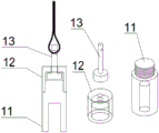
FIG. 2 is a schematic structural view of the screw connector;
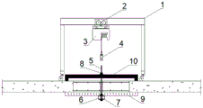
FIG. 3 is a view showing the completion of the installation of the post-cast strip installation apparatus according to example 1;
in the figure: the novel trolley comprises a trolley body (1), a slider (2), an electric winch (3), a screw connector (4), a screw (5), a plate bottom back ridge (6), a gasket (7), a nut (8), a template (9), a plate top back ridge (10), an upper convex and lower concave threaded sleeve (11), a concave hole-opening sleeve (12) and a non-threaded screw (13).
Detailed Description
The technical solution of the present patent will be described in further detail with reference to the following embodiments.
Reference will now be made in detail to embodiments of the present patent, examples of which are illustrated in the accompanying drawings, wherein like or similar reference numerals refer to the same or similar elements or elements having the same or similar function throughout. The embodiments described below with reference to the drawings are exemplary only for the purpose of explaining the present patent and are not to be construed as limiting the present patent.
Example 1
As shown in fig. 1, the present embodiment provides a post-cast strip construction device, which includes a movable hoisting trolley and a hoisting formwork assembly, wherein the movable hoisting trolley includes a trolley body 1, a slider 2, an electric winch 3 and a screw connector 4. The slider is installed on the dolly body, and electric capstan installs on the slider, demolishs the original couple of wire rope on the electric capstan, installs the screw connector.
The hoisting template assembly comprises a screw rod 5, a plate top back ridge 10, an aluminum alloy template 9 and a plate bottom back ridge 6, wherein a hole is formed in the middle of the template 9 and used for the screw rod 5 to penetrate through, the diameter of the hole is slightly larger than that of the screw rod 5 and that of a screw rod connector 4, and the plate top back ridge 10 and the plate bottom back ridge 6 are both installed on the screw rod and are respectively positioned on the upper side and the lower side of the template; the screw 5 is connected through a screw connector 4; as shown in fig. 2, the screw connector is composed of an upper convex and lower concave type threaded sleeve 11, a concave type opening sleeve 12 and a non-threaded screw 13, the upper part of the non-threaded screw 13 penetrates through the opening of the concave type opening sleeve 12 and is connected with a steel wire rope on the electric winch 3, and the upper convex thread of the upper convex and lower concave type threaded sleeve 11 is connected with the concave type opening sleeve 12 and is screwed tightly. The screw 5 is connected through a convex-concave type threaded sleeve 11 at the lowest end of the screw connector 4. Thereby utilizing the hoisting trolley to hoist the hoisting template component to the bottom of the post-cast strip.
The plate bottom back edge 6 is fixed with the screw 5 through a gasket 7 and a nut 8.
The templates 9 are freely assembled according to the size of the post-pouring belt.
In order to move conveniently, the bottom of the trolley body 1 is provided with a moving wheel.
In this embodiment, the back ridges are all square steel back ridges.
The trolley body 1, the slider 2 and the electric capstan 3 form a power device, and a steel wire rope of the electric capstan 3 is provided with a screw connector 4 for pulling the lower part to hoist the template assembly. The power device is positioned on a post-construction casting belt layer, namely the upper part of the hoisting template assembly. When the template assembly is hoisted, the screw rod connector 4 is connected with the screw rod 5, and the power device is started to pull the assembled template to rise to the bottom of the post-cast strip.
As shown in fig. 3, after the assembled template assembly is hoisted to the bottom of the post-cast strip, the template assembly is adjusted by using the trolley body 1 and the slider 2 so as to be positioned at the center of the post-cast strip. Reinforcing the screw 5 in the middle, firstly installing a sleeve, then installing a plate top back ridge 10 on the screw 5, placing two ends of the plate top back ridge 10 on the tops of the two side plates of the post-cast strip, installing a gasket 7 and a nut 8, and screwing the nut; and loosening the screw connector 4 at one end after the middle part is reinforced, repeating the installation process, loosening the screw connector 4 at the other end after the middle part is reinforced, and repeating the installation process. And after all the post-cast strips are installed, the two ends of the post-cast strip to be cast are plugged by using wire netting, and concrete is cast. And when the dismantling condition is met, dismantling the hoisting template assembly.
Claims (8)
1. The post-cast strip construction device is characterized by comprising a movable hoisting trolley and a hoisting template assembly, wherein the movable hoisting trolley comprises a trolley body (1), a slider (2), an electric winch (3) and a screw connector (4), the electric winch is installed on the trolley body through the slider, and the end part of a steel wire rope of the electric winch is connected with the screw connector; the hoisting template assembly comprises a screw (5), a plate top back edge (10), a template (9) and a plate bottom back edge (6), a hole is formed in the middle of the template (9) and used for the screw to pass through, and the plate top back edge (10) and the plate bottom back edge (6) are both installed on the screw (5) and are respectively located on the upper side and the lower side of the template; the plate top back ridge (10) is positioned at the upper part of the post-cast strip structure, the plate top back ridge (10) is vertical to the post-cast strip direction, the template (9) and the plate bottom back ridge (6) are positioned at the lower part of the post-cast strip structure, the template (9) is vertical to the post-cast strip direction, and the plate bottom back ridge (6) is parallel to the post-cast strip direction; the screw rod (5) is connected through the screw rod connector (4), so that the hoisting template assembly is hoisted to the bottom of the post-cast strip by using the trolley body (1).
2. The post-cast strip construction equipment according to claim 1, wherein the screw connector (4) is composed of an upper convex and lower concave type screw sleeve (11), a concave type open hole sleeve (12) and a non-screw (13), the upper part of the non-screw passes through the hole of the concave type open hole sleeve and is connected with a steel wire rope on the electric winch (3), and the upper convex screw of the upper convex and lower concave type screw sleeve is connected with the concave type open hole sleeve and is screwed down.
3. The post-cast strip construction device according to claim 1, characterized in that moving wheels are installed at the bottom of the trolley body (1).
4. Post-cast strip construction equipment according to claim 1, characterised in that the diameter of the right-way opening of the formwork (9) is greater than the diameter of the screw (5) and the screw connector (4).
5. The post-cast strip construction equipment of claim 1, wherein the back edges are all square steel back edges.
6. Post-cast strip construction equipment according to claim 1, characterised in that the plate bottom back edge (6) is fixed with the screw (5) by means of a washer (7) and a nut (8).
7. The post-cast strip construction device according to claim 1, wherein the upper part of the screw (5) is fixed on the plate top back edge (10) through a gasket (7) and a nut (8), and the section of the plate top back edge (10) is U-shaped.
8. Post-cast strip construction equipment according to claim 1, characterised in that the number of said screws (5) is at least three and must not be less than half the number of formwork.
Priority Applications (1)
| Application Number | Priority Date | Filing Date | Title |
|---|---|---|---|
| CN202122001451.5U CN215519944U (en) | 2021-08-24 | 2021-08-24 | Post-cast strip construction equipment |
Applications Claiming Priority (1)
| Application Number | Priority Date | Filing Date | Title |
|---|---|---|---|
| CN202122001451.5U CN215519944U (en) | 2021-08-24 | 2021-08-24 | Post-cast strip construction equipment |
Publications (1)
| Publication Number | Publication Date |
|---|---|
| CN215519944U true CN215519944U (en) | 2022-01-14 |
Family
ID=79793031
Family Applications (1)
| Application Number | Title | Priority Date | Filing Date |
|---|---|---|---|
| CN202122001451.5U Expired - Fee Related CN215519944U (en) | 2021-08-24 | 2021-08-24 | Post-cast strip construction equipment |
Country Status (1)
| Country | Link |
|---|---|
| CN (1) | CN215519944U (en) |
-
2021
- 2021-08-24 CN CN202122001451.5U patent/CN215519944U/en not_active Expired - Fee Related
Similar Documents
| Publication | Publication Date | Title |
|---|---|---|
| CN111561061A (en) | A prefabricated wall panel, wall structure and construction method thereof | |
| CN113668849A (en) | Post-cast strip pouring equipment and construction method thereof | |
| CN115126220B (en) | Parapet sliding formwork structure for steel structure building and construction method thereof | |
| CN111173263A (en) | Integral aluminum formwork based on narrow expansion joints | |
| CN103225396B (en) | Beam frame type construction template system | |
| CN106639042A (en) | Dry type connected concrete shear wall and dry type wall connecting method | |
| CN220848703U (en) | A connection assembly and support structure for aluminum-wood composite formwork | |
| CN203188612U (en) | Beam frame type building template system | |
| CN221590371U (en) | Detachable lifting ring anchor bolt device for cantilever type steel wire rope with inclined pull | |
| CN111058621B (en) | Early system of tearing open of floor template support-free | |
| CN212027094U (en) | Integral aluminum formwork based on narrow expansion joints | |
| CN206513689U (en) | Embedded bolt assembly | |
| CN214737292U (en) | Telescopic sliding formwork device for prefabricating steel-concrete composite beam | |
| CN212104746U (en) | Bottom die detachable steel bar truss floor support plate | |
| CN209341178U (en) | The prefabricated dedicated wire box of superimposed sheet | |
| CN209244293U (en) | Temporary fixing device for movable arched rod | |
| CN209815480U (en) | Prefabricated post hoisting structure | |
| CN103216087B (en) | A kind of two-way self-bearing type construction formwork system | |
| CN222044561U (en) | A prefabricated building wall connection reinforcement structure | |
| CN213741207U (en) | A formwork reinforcement device for basement exterior wall guide wall | |
| CN223446668U (en) | Wallboard mounting device | |
| CN215631590U (en) | Shear wall tie rod device and connecting structure at connecting part of cast-in-place concrete floor slab | |
| CN219471615U (en) | A simple protective device for the reserved hole for setting out wires | |
| CN219011511U (en) | An easy-to-install concrete prefabricated component | |
| CN203160565U (en) | Color plate water groove for steel structure building |
Legal Events
| Date | Code | Title | Description |
|---|---|---|---|
| GR01 | Patent grant | ||
| GR01 | Patent grant | ||
| CF01 | Termination of patent right due to non-payment of annual fee |
Granted publication date: 20220114 |
|
| CF01 | Termination of patent right due to non-payment of annual fee |