CN113602826B - Rail-bridge integrated rapid transit system and dam-turning transportation system - Google Patents
Rail-bridge integrated rapid transit system and dam-turning transportation system Download PDFInfo
- Publication number
- CN113602826B CN113602826B CN202110833039.1A CN202110833039A CN113602826B CN 113602826 B CN113602826 B CN 113602826B CN 202110833039 A CN202110833039 A CN 202110833039A CN 113602826 B CN113602826 B CN 113602826B
- Authority
- CN
- China
- Prior art keywords
- assembly
- rail
- bridge
- reloading
- loading
- Prior art date
- Legal status (The legal status is an assumption and is not a legal conclusion. Google has not performed a legal analysis and makes no representation as to the accuracy of the status listed.)
- Active
Links
Images


Classifications
-
- B—PERFORMING OPERATIONS; TRANSPORTING
- B65—CONVEYING; PACKING; STORING; HANDLING THIN OR FILAMENTARY MATERIAL
- B65G—TRANSPORT OR STORAGE DEVICES, e.g. CONVEYORS FOR LOADING OR TIPPING, SHOP CONVEYOR SYSTEMS OR PNEUMATIC TUBE CONVEYORS
- B65G63/00—Transferring or trans-shipping at storage areas, railway yards or harbours or in opening mining cuts; Marshalling yard installations
- B65G63/02—Transferring or trans-shipping at storage areas, railway yards or harbours or in opening mining cuts; Marshalling yard installations with essentially horizontal transit otherwise than by bridge
- B65G63/022—Transferring or trans-shipping at storage areas, railway yards or harbours or in opening mining cuts; Marshalling yard installations with essentially horizontal transit otherwise than by bridge for articles
-
- B—PERFORMING OPERATIONS; TRANSPORTING
- B65—CONVEYING; PACKING; STORING; HANDLING THIN OR FILAMENTARY MATERIAL
- B65G—TRANSPORT OR STORAGE DEVICES, e.g. CONVEYORS FOR LOADING OR TIPPING, SHOP CONVEYOR SYSTEMS OR PNEUMATIC TUBE CONVEYORS
- B65G63/00—Transferring or trans-shipping at storage areas, railway yards or harbours or in opening mining cuts; Marshalling yard installations
- B65G63/06—Transferring or trans-shipping at storage areas, railway yards or harbours or in opening mining cuts; Marshalling yard installations with essentially-vertical transit
- B65G63/062—Transferring or trans-shipping at storage areas, railway yards or harbours or in opening mining cuts; Marshalling yard installations with essentially-vertical transit for articles
-
- B—PERFORMING OPERATIONS; TRANSPORTING
- B65—CONVEYING; PACKING; STORING; HANDLING THIN OR FILAMENTARY MATERIAL
- B65G—TRANSPORT OR STORAGE DEVICES, e.g. CONVEYORS FOR LOADING OR TIPPING, SHOP CONVEYOR SYSTEMS OR PNEUMATIC TUBE CONVEYORS
- B65G67/00—Loading or unloading vehicles
- B65G67/60—Loading or unloading ships
- B65G67/603—Loading or unloading ships using devices specially adapted for articles
-
- B—PERFORMING OPERATIONS; TRANSPORTING
- B66—HOISTING; LIFTING; HAULING
- B66C—CRANES; LOAD-ENGAGING ELEMENTS OR DEVICES FOR CRANES, CAPSTANS, WINCHES, OR TACKLES
- B66C19/00—Cranes comprising trolleys or crabs running on fixed or movable bridges or gantries
Landscapes
- Engineering & Computer Science (AREA)
- Mechanical Engineering (AREA)
- Ocean & Marine Engineering (AREA)
- Aviation & Aerospace Engineering (AREA)
- Bridges Or Land Bridges (AREA)
Abstract
The invention discloses a rail-bridge integrated rapid transit system and a dam-turning transportation system, which solve the technical problem of low cargo transfer efficiency of multi-type intermodal transportation equipment at present. The rail-bridge integrated rapid transport system comprises a bridge frame, a loading and unloading hoisting device and a reloading device; the bridge frame is arranged on a river bank, a rail mounting position for the rail composition of the air rail system to penetrate is arranged on the bridge frame, and the air rail system can directly penetrate into the bridge frame; the loading and unloading lifting device is arranged on the bridge and moves on the bridge in a reciprocating manner to realize the transfer of goods between the ship and the reloading device; the reloading device is arranged in the area below the loading and unloading lifting device and the rail mounting position, can move in a reciprocating mode, and can transfer goods between the loading and unloading lifting device and the empty rail system. The rail-bridge integrated rapid transport system perfectly matches the grabbing and transporting equipment at the front edge of the shoreline with the empty rail, so that the empty rail system can realize the engineering application of container transportation at the front edge of the inland river shoreline.
Description
Technical Field
The application belongs to the technical field of cargo handling and transferring equipment, and particularly relates to a rail-bridge integrated rapid transit system and a dam-turning transportation system.
Background
At present, the front edge of an inland river shoreline is generally butted with a ship by adopting a shore bridge. The bank bridge is arranged on the bank side of a port and a wharf, a track is laid on the ground of the wharf, a cart walking device is arranged on a door frame assembly of the bank bridge, and the bank bridge is driven by the cart walking device to longitudinally walk along the track, namely a river bank. The lifting trolley is arranged on the front girder of the shore bridge, the lifting trolley can realize the lifting of goods (such as containers) and the vertical (along the bridge direction) movement along the river bank, and when the goods at different positions of a hoisting ship or the goods of different ships are loaded and unloaded, the bridge frame of the shore bridge is required to move along the longitudinal (transverse bridge direction) direction of the river bank.
The cargoes transported by the shore bridge are usually temporarily stored in ports, the port collecting and dredging system in China is mainly completed by roads (the occupied road ratio is up to 84 percent) at present, the road transportation environment pollution is large, the transportation cost is high, and particularly the problem of facility connection of the last kilometer of container ports becomes the first difficult problem of the development of the comprehensive transportation system in China.
Disclosure of Invention
In order to solve the technical problems, the invention provides a rail-bridge integrated rapid transit system and a dam-turning transport system, which perfectly match grabbing and transport equipment at the front edge of a shoreline with an air rail, so that the air rail system can realize the engineering application of container transport at the front edge of the inland river shoreline.
The technical scheme adopted for realizing the purpose of the invention is that the rail-bridge integrated rapid transport system comprises a bridge frame, a loading and unloading hoisting device and a reloading device; wherein:
the bridge is arranged on the river bank, and a track installation position for the track of the air rail system to penetrate is arranged on the bridge;
the loading and unloading hoisting device is arranged on the bridge and moves back and forth on the bridge so as to butt joint a ship and the reloading device;
the reloading device is arranged in the area below the loading and unloading lifting device and the rail mounting position, and the reloading device reciprocates in the area below the loading and unloading lifting device and the rail mounting position so as to be in butt joint with the loading and unloading lifting device and the air rail system.
Optionally, the bridge frame comprises a front girder, a rear girder, a support leg assembly and a bracket assembly; wherein:
the front girder is provided with a loading and unloading rail assembly along the axial direction of the front girder, the loading and unloading hoisting device is arranged on the front girder and can move back and forth along the loading and unloading rail assembly;
the replacing device is arranged on the supporting leg assembly;
the bracket constitute set up in the landing leg is constituteed, just the bracket constitute with the back girder is connected, the bracket is constituteed and is constituted the track installation position.
Optionally, the landing leg is constituteed into bilayer structure, including upper landing leg and lower floor's landing leg, the upper landing leg with be provided with the articulamentum that is used for connecting between the landing leg of lower floor, be provided with on the articulamentum and reserve interface, the platform of changing outfit is constituteed pass through reserve interface install in on the landing leg is constituteed.
Optionally, the leg assembly is a four-leg structure, and includes two front upper leg assemblies, two rear upper leg assemblies, two upper beam assemblies, a front connection assembly, a rear connection assembly, two middle beam assemblies, two front lower leg assemblies, and two rear lower leg assemblies; the two front upper leg assemblies are connected into an H-shaped structure through one of the upper cross beam assemblies, the two rear upper leg assemblies are connected into an H-shaped structure through the other upper cross beam assembly, and the two H-shaped structures form the upper-layer leg; the front connecting assembly and the rear connecting assembly are connected into a rectangular frame structure through the two middle cross beam assemblies to form the connecting layer; the two front lower leg assemblies are respectively connected with two ends of the front connecting assembly, and the two rear lower leg assemblies are respectively connected with two ends of the rear connecting assembly to form the lower-layer leg.
Optionally, the front connection assembly is connected with the front upper leg assembly and the front lower leg assembly through a flange structure; the rear connecting assembly is connected with the rear upper supporting leg assembly and the rear lower supporting leg assembly through a flange structure; the front connecting assembly and the rear connecting assembly are both provided with the reserved connecting interfaces.
Optionally, the front upper support leg assembly, the front lower support leg assembly, the rear upper support leg assembly and the rear lower support leg assembly are all box-shaped structures welded by plates, and a reinforcing partition plate is arranged in the middle of each box-shaped structure; the cross section size of the front upper supporting leg assembly and the front lower supporting leg assembly is larger than that of the rear upper supporting leg assembly and the rear lower supporting leg assembly.
Optionally, the bridge further includes an upper frame assembly and a pull rod assembly, the upper frame assembly is located at the top end of the bridge, and the support leg assembly is located at the bottom end of the bridge; a main beam assembly is arranged between the upper frame assembly and the supporting leg assembly, one end of the main beam assembly is fixed between the upper frame assembly and the supporting leg assembly to form the rear girder, and the other end of the main beam assembly extends outwards to form the front girder; two ends of the pull rod assembly are respectively connected with the upper frame assembly and the main beam assembly.
Optionally, the pull rod assembly comprises a pull rod assembly, a support assembly and a center pin assembly; the pull rod assembly comprises a pull rod plate and a pull rod; the support assembly comprises two support plates and a plurality of rib plates, the two ends of the main beam assembly and the upper frame assembly are respectively provided with the support assembly, and the support assembly and the pull rod plate of the pull rod assembly are fixedly connected through the center pin assembly.
Optionally, the front girder is a pre-arched girder having a pre-arching amount.
Optionally, the middle part of back girder is provided with the arm that hangs down, the bracket is constituteed to be installed on the arm that hangs down.
Optionally, the number of the bridge frames is N, wherein N is more than or equal to 2; the number of the reloading devices is N-1, and the reloading devices are arranged between every two adjacent bridges.
Optionally, the reloading device comprises a reloading platform assembly, a reloading transfer vehicle and a reloading track assembly; the reloading platform assembly is arranged between two adjacent bridges; the reloading track assembly is arranged on the reloading platform assembly; the reloading transfer trolley moves back and forth along the reloading track to be in butt joint with the loading and unloading lifting device and the empty rail system.
Optionally, the reloading platform assembly comprises a front cross beam assembly, a rear cross beam assembly, a longitudinal beam assembly, a reinforcing beam assembly and a bolting plate assembly; wherein: the front cross beam assembly and the rear cross beam assembly are connected into a whole through the longitudinal beam assembly; the stiffening beam assembly is mounted on the longitudinal beam assembly; the bolted plate assembly is arranged on the front beam assembly and the rear beam assembly and used for connecting the reloading platform assembly and the bridge.
Optionally, the handling and hoisting device comprises N translation cars, a track beam and N-1 lifting cars; the translation vehicle moves along the loading and unloading rail assembly, and a connecting hanger is arranged on the translation vehicle; the track beam is arranged on a connecting hanger of the N translation vehicles, and the axis of the track beam is perpendicular to the translation direction of the translation vehicles; the N-1 lifting vehicles are respectively arranged on the track beams and comprise frame assemblies, track traveling mechanisms, lifting appliances and lifting mechanisms for lifting the lifting appliances, the track traveling mechanisms and the lifting mechanisms are respectively arranged on the frame assemblies, and the track traveling mechanisms are matched with the track beams so that the lifting vehicles move along the track beams under the driving of the track traveling mechanisms.
Optionally, the number of the bridges is 3; the loading and unloading hoisting device comprises 3 translation vehicles, 1 track beam and 2 lifting vehicles; 2 of the 3 translation vehicles positioned on the outer side are provided with translation traveling mechanisms, and the translation vehicles are driven by the translation traveling mechanisms to move along the loading and unloading rail assembly; the track beam is hung, installed and fixed through the connection of the 3 translation vehicles, and the 2 lifting vehicles are arranged along the axial direction of the track beam.
Optionally, the rail-bridge integrated rapid transit system further comprises a fixed pile foundation, and the bridge is fixedly connected with the pile foundation through anchor bolts.
Based on the same inventive concept, the invention also correspondingly provides a dam-overturning transportation system, which comprises two rail-bridge integrated rapid transportation systems and an air rail system; the two rail-bridge integrated rapid transit systems are respectively arranged on the upstream river bank and the downstream river bank of the river dam; the air rail system is connected with the two rail-bridge integrated rapid transit systems so as to transfer goods between the two rail-bridge integrated rapid transit systems.
Optionally, the number of the bridges is 6, wherein 3 bridges are arranged on the bank upstream of the dam, and the remaining 3 bridges are arranged on the bank downstream of the dam; the upstream 3 bridges and the downstream 3 bridges are respectively provided with a set of loading and unloading hoisting device; the upstream 3 bridges and the downstream 3 bridges are respectively provided with two reloading devices, and each reloading device is respectively installed between two adjacent bridges.
According to the technical scheme, the rail-bridge integrated rapid transport system comprises a bridge frame, a loading and unloading lifting device and a reloading device. The bridge is arranged on the river bank and can extend above a ship in the river channel, the structure of the bridge is improved aiming at the existing bank bridge, a rail installation position for the rail assembly of the air rail system to penetrate through is arranged on the bridge, and the air rail system can directly penetrate through the bridge; the loading and unloading hoisting device is arranged on the bridge and moves back and forth on the bridge, and can be directly butted with the ship and the reloading device, so that the cargo is transferred between the ship and the reloading device; the reloading device is arranged in the area below the loading and unloading lifting device and the rail mounting position, can move in a reciprocating mode, and can be directly abutted to the loading and unloading lifting device and the empty rail system, so that the transfer of goods between the loading and unloading lifting device and the empty rail system is achieved.
Compared with the prior art, the rail-bridge integrated rapid transport system provided by the invention realizes seamless butt joint of ship transportation and a mature air rail system through the bridge, the loading and unloading hoisting device and the reloading device, so that the air rail system realizes the engineering application of container transportation at the front edge of the inland river shoreline, a novel transportation scene of the air rail system is developed, and the development of multi-type intermodal transportation is promoted.
The rail-bridge integrated rapid transport system provided by the invention adopts a vehicle-ship container direct taking mode to directly lift, transport and store the containers, reduces the accurate positioning times of reloading the containers, improves the transport efficiency of the system, accords with the development direction of an intelligent container station, and enables the loading, unloading and transporting operations of goods to be more flexible.
In addition, the rail and bridge integrated rapid transit system provided by the invention has the advantages that the rail installation positions for the rails of the air rail system to form the penetrating rail are arranged on the bridge frame, the air rail system can directly penetrate through the bridge frame, and on one hand, the air rail system serves as the balance weight of the bridge frame, so that the bridge frame in the rail and bridge integrated rapid transit system provided by the invention does not need to be additionally provided with a balance weight mechanism, is reasonable in integral stress and has higher anti-overturning capacity; on the other hand, the bridge serves as one of the supporting piles of the air rail system, and the cost of the supporting structure of the air rail system is saved.
The dam-turning transportation system provided by the invention comprises two rail-bridge integrated rapid transportation systems and an air rail system, wherein the two rail-bridge integrated rapid transportation systems are respectively arranged on the upstream river bank and the downstream river bank of a dam, the two rail-bridge integrated rapid transportation systems are integrally butted through the air rail system, the air rail system is arranged on the river bank along the flow direction of a river channel, and the air rail system extends at the upstream and the downstream of the dam.
By adopting the rail-bridge integrated rapid transport system, cargo transport modes are completed in the air, and the requirement on the geological environment at the front edge of a shoreline is reduced, so that the bridge structure can be constructed on a dam shoreline, and the bridge structure is matched with an air rail system to realize a dam-overturning operation mode of 'no excessive cargo passing' and solve the problems of difficult dam passing and slow dam passing of the current inland waterway ships.
Drawings
Fig. 1 is a schematic structural diagram of a rail-bridge integrated rapid transit system in embodiment 1 of the present invention.
Fig. 2 is a side view of fig. 1.
Fig. 3 is a front view of fig. 1.
Fig. 4 is a schematic structural diagram of a middle bridge in the rail-bridge integrated rapid transit system of fig. 1.
Fig. 5 is a schematic structural view of a leg assembly of the bridge of fig. 4.
Fig. 6 is a schematic structural view of a main beam assembly in the bridge frame of fig. 4.
Fig. 7 is a front view of the main beam assembly of fig. 6.
Fig. 8 is a schematic structural view of an upper frame assembly in the bridge frame of fig. 4.
Fig. 9 is a partially enlarged view of a portion a of fig. 4.
Fig. 10 is a partially enlarged view of fig. 4 at B.
Fig. 11 is a schematic structural view of a unloading and hoisting device in the rail-bridge integrated rapid transit system of fig. 1.
Fig. 12 is a schematic structural diagram of a reloading device in the rail-bridge integrated rapid transit system of fig. 1.
Fig. 13 is a schematic structural view of a component of the reloading platform in the reloading apparatus of fig. 12.
Fig. 14 is a first longitudinal movement use state diagram of the rail-bridge integrated rapid transit system of fig. 1.
Fig. 15 is a second longitudinal movement use state diagram of the rail-bridge integrated transporting system of fig. 1.
Fig. 16 is a first lateral movement use state diagram of the rail-bridge integrated short-cut system of fig. 1.
Fig. 17 is a second lateral movement use state diagram of the rail-bridge integrated rapid transit system of fig. 1.
Fig. 18 is a third diagram of the lateral movement use state of the rail-bridge integrated short-cut system in fig. 1.
Fig. 19 is a schematic structural view of a dam-turned transportation system in embodiment 2 of the present invention.
Description of reference numerals:
100-loading and unloading a hoisting device; 110-translation vehicle, 111-connection hanger; 120-a track beam; 130-lifting vehicle, 131-vehicle frame assembly, 132-track traveling mechanism, 133-lifting mechanism and 134-lifting appliance; 140-trolley line electricity-taking device.
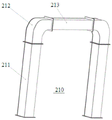
200-a bridge frame; 210-upper frame assembly, 211-upright post assembly, 212-elbow joint assembly, 213-connecting beam assembly; 220-pull rod assembly, 221-pull rod assembly, 2211-pull rod plate, 2212-pull rod, 222-support assembly, 2221-support plate, 2222-rib plate and 223-center pin assembly; 230-main beam assembly, 231-front beam, 232-rear beam, 233-vertical arm, 234-middle connecting section and 235-walking plate; 240-assembly and disassembly track; 250-support leg assembly, 2501-upper support leg, 2502-lower support leg, 2503-connecting layer, 251-front upper support leg assembly, 252-upper beam assembly, 253-front connecting assembly, 254-front lower support leg assembly, 255-rear upper support leg assembly, 256-rear connecting assembly, 257-middle beam assembly, 258-rear lower support leg assembly and 259-reserved connecting interface; 260-bracket composition; 270-fence and accessories.
300-air rail system; 310-track composition; 320-freight car.
400-a changing device, 410-a changing platform assembly, 411-a front beam assembly, 412-a rear beam assembly, 413-a longitudinal beam assembly, 414-a reinforcing beam assembly, 415-a bolting plate assembly and 420-a changing transfer vehicle; 430-replacing the track; 440-protection and accessories.
500-a container; 600-a ship; 700-river dam.
Detailed Description
In order to make the present application more clearly understood by those skilled in the art to which the present application pertains, the following detailed description of the present application is made with reference to the accompanying drawings.
Aiming at the technical problems of complex loading, unloading and transferring operation and low efficiency of the existing multi-type intermodal transportation equipment, the invention provides a rail-bridge integrated rapid transit system, which is used for realizing the grabbing and transporting of containers at the front edge and realizing the seamless connection with an air rail. The basic inventive concept of the present invention is as follows:
the rail-bridge integrated rapid transportation system provided by the invention comprises a bridge frame, a loading and unloading hoisting device and a reloading device. The bridge is arranged on the river bank and can extend above a ship in the river channel, the structure of the bridge is improved aiming at the existing bank bridge, a rail installation position for the rail assembly of the air rail system to penetrate through is arranged on the bridge, and the air rail system can directly penetrate through the bridge; the loading and unloading hoisting device is arranged on the bridge and moves back and forth on the bridge, and can be directly butted with the ship and the reloading device, so that the cargo is transferred between the ship and the reloading device; the reloading device is arranged in the area below the loading and unloading lifting device and the rail mounting position, can move in a reciprocating mode, and can be directly abutted to the loading and unloading lifting device and the empty rail system, so that the transfer of goods between the loading and unloading lifting device and the empty rail system is achieved.
Therefore, the rail-bridge integrated rapid transport system provided by the invention realizes seamless butt joint of ship transportation and a mature air rail system through the bridge, the loading and unloading hoisting device and the reloading device, so that the air rail system realizes the engineering application of container transportation at the front edge of an inland river shoreline, a novel transportation scene of the air rail system is opened up, and the development of multi-type combined transportation is promoted.
The above technical solution of the present invention is described in detail with reference to the following specific embodiments:
example 1:
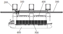
the embodiment provides a rail-bridge integrated rapid transit system, and particularly referring to fig. 1 to 3, the system comprises a bridge frame 200, a loading and unloading lifting device 100 and a reloading device 400. The crane span structure 200 sets up on the river bank, and the front end of crane span structure 200 can extend to the top of the ship 600 in the river course, compares in current bank bridge, is provided with the track installation position that is used for supplying the track component 310 of air rail system 300 to wear to establish on the crane span structure 200, and air rail system 300 can directly wear to locate in the crane span structure 200. The handling trolley 100 is installed on the bridge 200, the handling trolley 100 can reciprocate on the bridge 200, and the handling trolley 200 can directly butt joint the ship 600 and the reloading device 400, so that the cargo can be transferred between the ship 600 and the reloading device 400. The reloading device 400 is arranged in the region below the loading and unloading swing device 100 and the rail mounting position, and the reloading device can move back and forth, that is, the reloading device 400 can shuttle in the region below the loading and unloading swing device 100 and the air rail system 300, so that the loading and unloading swing device 100 and the air rail system 300 are directly butted, and the transfer of goods between the loading and unloading swing device 100 and the air rail system 300 is realized.
When the ship 600 carries the cargo below the bridge 200, the handling trolley 100 moves along the bridge 200 to move to the position above the ship 600, and the handling trolley 100 transfers the cargo on the ship 600 to the position above the reloading device 400. The reloading device 400 starts moving after receiving the goods, and transfers the goods to the lower part of the empty rail system 300, and the goods are transported to the far end by the empty rail system 300. The vehicle-ship container direct taking mode is adopted, and goods are directly lifted, transferred and stocked, so that the goods are more flexibly loaded, unloaded and transferred.
In the whole rail-bridge integrated rapid transit system, the bridge frame 200 is the supporting base of the system, and the empty rail system 300, the handling and hoisting device 100 and the reloading device 400 are either installed on the bridge frame 200 or supported and fixed through the bridge frame 200. The bridge 200 of the present invention can be obtained by arranging the rail installation site on the leg or the back beam of the existing shore bridge in consideration of the need of the air rail system 300 for penetrating, and the specific structure of the rail installation site can refer to the installation structure of the rail assembly 310 in the air rail system 300. The specific structure of the bridge and its rail mounting locations is not limiting of the present invention.
Referring specifically to fig. 4, in this embodiment, the bridge 200 includes a front girder 231, a rear girder 232, a leg assembly 250, and a corbel assembly 260. The front girder 231 is provided with a loading and unloading rail assembly 240 along the axial direction thereof, the loading and unloading trolley 100 is mounted on the front girder 231, and the loading and unloading trolley 100 can reciprocate along the loading and unloading rail assembly 240. The reloading device 400 is mounted on the leg assembly 250 of the bridge 200. The bracket assembly 260 is disposed in the supporting leg assembly 250, the bracket assembly 260 is connected to the rear girder 232, and the bracket assembly 260 is used for installing the rail assembly 310 of the air rail system 300, that is, the bracket assembly 260 constitutes the rail installation site. Compared with the existing shore bridge structure, the bridge frame 200 of the invention omits a counterweight on a rear girder, and designs the bracket assembly 260 for the air rail system 300, and the specific structure of the bracket assembly 260 can refer to the support structure of the support pile in the air rail system 300 to the track assembly 310, and the specific content is not described herein. Other specific structures of the bridge frame can refer to the existing shore bridge, and the specific content is not limited by the invention.
Referring to fig. 4, the bridge frame 200 provided in this embodiment includes an upper frame assembly 210, a leg assembly 250, a main beam assembly 230, a pull rod assembly 220, a loading and unloading rail assembly 240, and a bracket assembly 260. The upper frame assembly 210, the leg assembly 250, the main beam assembly 230 and the pull rod assembly 220 form a main frame of the bridge frame 200, the upper frame assembly 210 is located at the top end of the main frame, and the leg assembly 250 is located at the bottom end of the main frame. The main beam assembly 230 is located between the upper frame assembly 210 and the supporting leg assembly 250, the main beam assembly 230 is perpendicular to the upper frame assembly 210 and the supporting leg assembly 250, one end of the main beam assembly 230 is fixed between the upper frame assembly 210 and the supporting leg assembly 250 to form a rear girder 232, the other end of the main beam assembly 230 extends outwards to form a front girder 231, and the front girder 231 is a cantilever beam. The two ends of the pull rod assembly 220 are respectively connected with the upper frame assembly 210 and the main beam assembly 230, the upper frame assembly 210 and the front girder 231 are connected through the pull rod assembly 220, and the upper frame assembly 210 and the rear girder 232 ensure the rigidity of the main beam assembly 230 and the overall stability of the bridge frame 200. The loading and unloading rail assembly 240 is arranged on the front girder 231 along the axial direction of the main beam assembly 230 and is used for installing a device for loading, unloading and lifting cargoes. The bracket assembly 260 is disposed in the support leg assembly 250, and the bracket assembly 260 is connected to the rear crossbeam 232, and the bracket assembly 260 can support the rail assembly 310 of the conventional air rail system 300, so that the air rail system 300 is directly inserted into the bridge frame 200. For safety, the bridge 200 of the present embodiment further includes a rail and accessory assembly 270.
In order to facilitate the connection of the components of the bridge 200, in this embodiment, flange interfaces are reserved for the components, and the final connection is implemented by bolts. In order to facilitate transportation and installation, in the embodiment, the upper frame assembly 210, the support leg assembly 250 and the main beam assembly 230 are designed in a segmented manner, and all the parts are connected through flanges, so that the transportation requirement of a common road can be met. The structure of the components of the bridge 200 will be described in detail below.
The leg assembly 250 is one of the core components of the bridge 200, and the weight of the bridge 200 and the load of the handling trolley 100 and the goods carried on the bridge 200 are all borne by the leg assembly 250, so that the structure of the bridge needs to be designed strictly by combining the overall stress characteristics of the leg assembly 250. For the stability of the whole structure, the bridge frame 200 is designed to be of a four-leg structure, and the legs are connected together by a cross beam, so that the whole stability of the legs is ensured. In addition, in order to facilitate the docking with the air rail system 300, in this embodiment, the leg assembly 250 is designed to be a double-layer structure, and includes an upper-layer leg 2501 and a lower-layer leg 2502, a connection layer 2503 for connection is disposed between the upper-layer leg 2501 and the lower-layer leg 2502, as shown in fig. 5, a reserved connection interface 259 is disposed on the connection layer 2503, so as to connect to other devices. Of the upper leg 2501 and the lower leg 2502, the upper leg 2501 is used for mounting the main beam assembly 230, and the lower leg 2502 mainly plays a bearing role.
Referring to fig. 5, leg assembly 250 includes two front upper leg assemblies 251, two rear upper leg assemblies 255, two upper beam assemblies 252, a front connection assembly 253, a rear connection assembly 256, two middle beam assemblies 257, two front lower leg assemblies 254, and two rear lower leg assemblies 258. Wherein: the two front upper leg assemblies 251 are connected into an H-shaped structure through one upper crossbeam assembly 252, the two rear upper leg assemblies 255 are connected into an H-shaped structure through the other upper crossbeam assembly 252, and the two H-shaped structures form an upper leg 2501; the front connection assembly 253 and the rear connection assembly 256 are connected into a rectangular frame structure through two middle cross beam assemblies 257 to form a connection layer 2503; two front lower leg assemblies 254 are connected to the two ends of the front connection assembly 253, and two rear lower leg assemblies 258 are connected to the two ends of the rear connection assembly 256, respectively, to form a lower leg 2502.
Specifically, the front upper support leg assembly 251, the front lower support leg assembly 254, the rear upper support leg assembly 255 and the rear lower support leg assembly 258 are all of a box-shaped structure welded by plates, and a reinforcing partition plate is arranged in the middle of the box-shaped structure to ensure the stability of the structure. When the leg assembly 250 is designed, the stress of the front and rear legs is analyzed and obtained to have larger difference by combining the integral stress characteristic of the bridge frame 200, so that the front and rear legs are designed independently according to the stress characteristic, the cross section sizes of the front upper leg assembly 251 and the front lower leg assembly 254 are larger than the cross section sizes of the rear upper leg assembly 255 and the rear lower leg assembly 258, and the strength of the legs is ensured to be matched with the load.
To facilitate the connection of the parts of the leg assembly 250, the front connection assembly 253 is connected to the front upper leg assembly 251 and the front lower leg assembly 254 by a flange structure; the rear connecting assembly 256 is connected with the rear upper leg assembly 255 and the rear lower leg assembly 258 through flange structures; reserved connection interfaces 259 are arranged on the front connection assembly 253 and the rear connection assembly 256. The front connection assembly 253 and the rear connection assembly 256 are connected with three-side interfaces (a front/rear upper leg assembly 255, a front/rear lower leg assembly 258 and a middle cross beam assembly 257) through arc transition, so that stress concentration of the structure is avoided, and the integral stability of the leg assembly 250 is ensured.
The main beam assembly 230 is another core component of the bridge 200, and a longer main beam cantilever, i.e., a front beam 231, is designed according to the functional requirements of the bridge 200 in the overall structural design, as shown in fig. 6. In consideration of the force characteristics of the cantilever, in this embodiment, a certain pre-arching is provided on the front girder 231 to resist the downward deflection of the front cantilever, as shown in fig. 7, and the pre-arching amount d (d represents the vertical pre-bending height) is calculated according to the cantilever length of the front girder 231 and the load. The front girder 231 is designed as a pre-arched girder, reducing the influence of the movement irregularity of the handling trolley 100 due to the cantilever downwarping.
In order to facilitate later transportation and installation of the main beam assembly 230, the main beam assembly 230 is manufactured in segments, and in this embodiment, the two main beams of the front span are divided into 6 segments in total, as shown in fig. 7, wherein the front span, i.e., the front girder 231, is divided into two segments, and the rear span, i.e., the rear girder 232, is divided into one segment. The middle part of the rear girder 232 is provided with a vertical arm 233 for mounting a corbel assembly 260.
The upper frame assembly 210 and the drawbar assembly 220 are structurally designed to increase the rigidity of the main beam assembly 230. Wherein the upper frame assembly 210 mainly provides a pivot point for the drawbar assembly 220 to ensure the stability of the drawbar assembly 220, and the drawbar assembly 220 pulls the main beam assembly 230.
Referring to fig. 8, in the present embodiment, the upper frame assembly 210 includes a column assembly 211, an elbow joint assembly 212, and a connecting beam assembly 213, which are integrally shaped like a frame, and two column assemblies 211 of the upper frame assembly 210 are respectively connected to the middle connecting section 234 of the two-span main beam of the main beam assembly 230. The elbow assembly 212 is designed to avoid stress concentrations in the structure. The upper frame assembly 210 is also designed to have a box-type structure, and is connected to the lower frame assembly in a flange manner by means of a sectional design so as to ensure later transportation and installation.
Referring to fig. 9 and 10, in the present embodiment, the drawbar assembly 220 includes a drawbar assembly 221, a support assembly 222, and a center pin assembly 223. Wherein: the drawbar assembly 221 includes a drawbar plate 2211 and a drawbar 2212, in this embodiment, the drawbar 2212 is made of a steel pipe, that is, the drawbar assembly 221 is formed by welding the drawbar plate 2211 and the steel pipe. The support assembly 222 includes two support plates 2221 and a plurality of rib plates 2222, the rib plates 2222 ensure the connection strength of the support plates 2221, and the support assembly 222 and the tie rod plate 2211 of the tie rod assembly 221 are fixedly connected by the center pin assembly 223. Because the pull rod assembly 220 is used for connecting the main beam assembly 230 and the upper frame assembly 210, in this embodiment, the two ends of the main beam assembly 230 and the upper frame assembly 210 are both provided with the support assembly 222, in order to ensure the connection strength of the support, the support assembly 222 on the main beam assembly 230 is installed on the walking plate 235 of the main beam assembly 230, and the walking plate 235 adopts a fish belly type structure design, so as to provide enough space for the design of the support assembly 222 and ensure the design strength of the support assembly 222.
The bracket assembly 260 is arranged in the support leg assembly 250 of the bridge 200 of the embodiment, so that the bridge 200 can be perfectly matched with the existing air rail system 300, and on one hand, the air rail system 300 serves as a counterweight of the bridge 200, so that the bridge 200 provided by the invention does not need to be additionally provided with a counterweight mechanism, is reasonable in overall stress and has higher anti-overturning capacity; on the other hand, the bridge frame 200 serves as one of the supporting piles of the air rail system 300, so that the supporting structure cost of the air rail system 300 is saved. In the rail-bridge integrated rapid transit system provided by the invention, the bridge frame 200 adopts the structural arrangement mode, so that the structural stress of a rail-bridge system is facilitated, the anti-overturning capacity of the system is improved, and the design requirement of pier foundation is also reduced.
The handling and hoisting device 100 may be a trolley traveling mechanism of an existing shore bridge system, or other cargo transportation devices, and the specific structure is not limited by the invention. Referring specifically to fig. 11, handling trolley 100 includes a translation car 110, a track beam 120, and a lift car 130; the translation vehicle 110 is used for driving the track beam 120 and the lifting vehicle 130 to move vertically (along the bridge direction) along the river bank, and the translation vehicle 110 is provided with a connecting hanger 111; the track beam 120 is installed on the coupling hanger 111 of the translational vehicle 110, and the axis of the track beam 120 is perpendicular to the translational direction of the translational vehicle 110, and the track beam 120 is used for providing a walking track for the lift truck 130, so that the lift truck 130 can walk along the track beam 120, that is, along the longitudinal direction (transverse bridge direction) of the river bank; the hoist 130 functions to lift a spreader 134 and/or freight and drive the spreader 134 and/or freight to be transferred in a longitudinal direction (transverse direction) of the river bank, the hoist 130 is mounted on the rail beam 120, the hoist 130 includes a frame assembly 131, a rail running mechanism 132, a spreader 134 and a lifting mechanism 133 for lifting the spreader 134, the rail running mechanism 132 and the lifting mechanism 133 are respectively mounted on the frame assembly 131, and the rail running mechanism 132 cooperates with the rail beam 120 so that the hoist 130 moves along the rail beam 120 under the driving of the rail running mechanism 132. The trolley line electricity-taking device 140 is arranged on the track beam 120 and used for supplying power to the lifting vehicle 130.
Because the track beam 120 has a certain length, the track beam 120 is generally driven by a plurality of the translation vehicles 110 to move together, that is, the handling and hoisting device 100 includes N translation vehicles 110, the N translation vehicles 110 are sequentially arranged along the axial direction of the track beam 120, the track beam 120 is installed on the connection hanger 111 of the N translation vehicles 110, and each translation vehicle 110 should be uniformly and symmetrically distributed on the track beam 120, so as to avoid uneven stress on the track beam 120. The specific number of the lifting trucks 130 can also be set as a plurality according to the capacity design, i.e. the handling trolley 100 comprises N-1 lifting trucks 130, N-1 lifting trucks 130 are respectively mounted on the track beam 120, and one lifting truck 130 is arranged between two adjacent translation trucks 110.
In this embodiment, there are 3 bridge frames 200, and correspondingly, the handling trolley 100 includes 3 translation cars 110, 1 track beam 120, and 2 lifting cars 130. The 3 translation vehicles 110 are respectively installed on the front girders 231 of the 3 bridges 200, the 2 translation vehicles 110 located at the outer side are provided with translation traveling mechanisms, the middle translation vehicle 110 is only used for supporting and guiding, and the translation traveling mechanisms drive the translation vehicles 110 to axially travel along the track beams 120. The specific structure of the translation traveling mechanism can refer to any existing traveling mechanism, such as a trolley traveling mechanism of a shore bridge system, and the specific structure of the translation traveling mechanism is not limited in the invention. The translation running gear in this embodiment includes motor, reduction gear, transmission shaft and the walking wheel that connects gradually, installs the transmission shaft and the walking wheel that are used for walking on the track equally on middle translation car 110, because do not set up the motor, consequently middle translation car 110 does not do the drive and uses, only plays the effect of support and direction.
The loading and unloading lifting device 100 can independently finish the transportation of goods in the longitudinal direction (transverse direction), the vertical direction (along bridge direction) and the vertical direction of the river bank, so that the crane travel mechanism of the existing bank bridge can be omitted at the bottom of the bridge frame 200, and the foundation of the system only needs to be mainly fixed pile foundations. In the rail-bridge integrated rapid transit system of the embodiment, the bridge frame 200 is directly installed on the fixed pile foundation, and the supporting leg assembly 250 of the bridge frame 200 is fixedly connected with the pile foundation through the anchor bolt.
The reloading device 400 is disposed in the area below the handling trolley 100 and the empty rail system 300, and the reloading device 400 is mounted on the leg assemblies 250 of the bridge 200 in consideration of the mounting height of each device, for example, the reloading device 400 is mounted on the connection layer 2503 of the leg assemblies 250, and of course, the reloading device 400 may be simultaneously supported by two bridges 200. In this embodiment, the exchanging device 400 is installed on the reserved connecting interface 259 of two adjacent bridges 200. Since the reloading device 400 requires two bridges 200 to be supported simultaneously, the number of bridges 200 should be more than 2. The number of the reloading devices 400 is one less than that of the bridges 200, so that each reloading device 400 is ensured to be respectively arranged between two bridges 200 adjacent to the reloading device.
The reloading device 400 comprises a reloading platform assembly 410, a reloading transfer car 420 and a reloading track 430, wherein the reloading track 430 assembly is arranged on the reloading platform assembly 410, and the reloading transfer car 420 moves along the reloading track 430 assembly to butt the loading and unloading lifting device 100 and the empty rail system 300; the leg assembly 250 of the bridge frame 200 is provided with a reserved connection interface 259, and the reloading platform assembly 410 is installed on the bridge frame 200 through the reserved connection interface 259. In order to improve the operation safety, a stop assembly is further arranged in the reloading track 430, and is mainly used for providing a track limiting function for the reloading transfer trolley 420. For safety reasons, the reloading device 400 provided by this embodiment further comprises a protection and accessory component 240.
The reloading platform assembly 410 provides structural support to the reloading device 400 and designs a cantilever of a certain length for front end boxing operation according to system requirements. The reloading transfer car 420 mainly realizes the longitudinal (along the bridge direction) transportation of goods to the position below the empty rail line, has a jacking function, meets the requirement of the box grabbing operation function of the goods transportation car 320 of the empty rail system 300, and the reloading transfer car 420 can refer to any existing rail goods transfer car, such as a container 500 transfer car of the empty rail system 300, and the specific structure of the reloading transfer car 420 is not limited by the invention.
The reloading platform assembly 410 is designed mainly according to a reloading transfer cart 420, and referring to fig. 12 and 13 in particular, in this embodiment, the reloading platform assembly 410 includes a front cross member assembly 411, a rear cross member assembly 412, a longitudinal member assembly 413, a reinforcing member assembly 414, and a bolting plate assembly 415. The front cross beam assembly 411 and the rear cross beam assembly 412 are connected into a whole through a longitudinal beam assembly 413, and the center of the front cross beam assembly 411 protrudes forwards to form a cantilever for the operation of a front end joint box; the stiffening beam assembly 414 is installed on the longitudinal beam assembly 413, and the bolting plate assembly 415 is installed on the front cross beam assembly 411 and the rear cross beam assembly 412, and is used for connecting the reloading platform assembly 410 and the bridge frame 200.
The rail-bridge integrated rapid transit system provided by this embodiment is configured with a corresponding master control system and a corresponding detection device, the master control system and the detection device operate in a conventional connection manner disclosed in the related art, and detection signals of the detection device include, but are not limited to, a spreader 134 moving position signal, a translation vehicle 110 moving position signal, a lifting vehicle 130 moving position signal, and the like.
Referring to fig. 14 to 18, the operation principle of the rail-bridge integrated transportation system will be described in detail below by taking a rail-bridge integrated transportation system configured with 3 bridges 200, 2 reloading devices 400 (hereinafter referred to as a reloading platform 1 and a reloading platform 2), 3 translation vehicles 110, 1 track beam 120, and 2 lifting vehicles 130 as an example:
the rail-bridge integrated rapid transit system controls the loading and unloading lifting device 100 to drive the container 500 lifting appliance 134 to move transversely (transverse bridge direction, parallel to the ship length and lower common mode) and longitudinally (bridge direction, perpendicular to the ship length and lower common mode) through positioning the container 500 on the ship 600, so that the centering operation on the container 500 is realized. Lateral movement of the container 500 as shown in fig. 14 and 15, the hoist carriage 130 moves the spreader 134 along the rail beam 120 so that the spreader 134 is laterally centered with the container 500 to be hoisted. Longitudinal movement of the container 500 as shown in fig. 16 and 18, the 3 translatory vehicles 110 move the rail beams 120 and the lift trucks 130 along the front longerons 231 of the bridge 200 so that the spreaders 134 are longitudinally aligned with the hoisted container 500.
After the rail-bridge integrated rapid transit system judges that the spreader 134 and the container 500 are aligned, the lifting vehicle 130 performs winding work, lowers the spreader 134, grabs the container 500 on the ship 600, and then lifts the container 500 to a safe height.
And the rail-bridge integrated rapid transit system judges that the container grabbing operation is finished, identifies the distances between the grabbed container 500 and the number 1 and number 2 reloading platforms, and selects the platform close to the grabber to realize the container falling operation.
The lift trucks 130 and the translation trucks 110 of the handling and hoisting device 100 drive the container 500 to perform lateral and longitudinal adjustment, thereby realizing the centering operation of the container 500 and the reloading transfer truck 420 of the reloading device 400, and realizing the box falling on the reloading transfer truck 420.
The rail-bridge integrated rapid transit system judges that the container 500 is completely unloaded, the loading and unloading transfer car drives the container 500 to move along the longitudinal direction, the container 500 arrives below the appointed empty rail line to stop, and the container 500 is jacked to the appointed height.
After the freight motor cars 320 of the air rail system 300 are aligned with the container 500, the container grabbing operation is performed, and then the container 500 is transported to a designated position.
In the rail-bridge integrated rapid transport system provided by the embodiment, the empty rail system 300 and the handling and lifting device 100 are in seamless butt joint through the reloading device 400, and the container direct taking mode of 'vehicle-ship' is adopted to directly hoist, transport and pile the containers 500, so that the accurate positioning times of reloading the containers 500 are reduced, the transportation efficiency of the system is improved, the development direction of an intelligent container 500 station is met, and the molten iron combined transport of the railway containers 500 is realized.
Example 2:
based on the same inventive concept, the embodiment provides a dam-overturning transportation system, which adopts the air rail system 300 to realize a dam-overturning operation mode of 'no cargo passing ship' aiming at the condition that ships in inland waterway pass the dam difficultly and pass the dam slowly.
Referring to fig. 19, the dam-overturning transportation system includes an air rail system 300 and two rail-bridge integrated short-cut transportation systems of the above embodiment 2, the two rail-bridge integrated short-cut transportation systems are respectively disposed on the river bank upstream and the river bank downstream of the river dam 700, the two rail-bridge integrated short-cut transportation systems are butted into a whole through the air rail system 300, the air rail system 300 is disposed on the river bank along the flow direction of the river channel, and the air rail system 300 extends upstream and downstream of the river dam 700 and covers the river dam 700 of the river channel. The bridges 200 of the two rail-bridge integrated rapid transit system are respectively arranged on the river bank at the upstream and the river bank at the downstream of the dam 700, and the air rail system 300 is respectively butted with the handling and hoisting device 100 of each bridge 200. The specific number of bridges 200 depends on the capacity of the inland waterway ship 600, and the present invention is not limited thereto.
In this embodiment, the number of bridges 200 is 6, wherein 3 bridges 200 are disposed on the bank upstream of the dam 700, and the remaining 3 bridges 200 are disposed on the bank downstream of the dam 700; a set of handling trolley 100 is provided on each of the upstream 3 bridges 200 and the downstream 3 bridges 200, so that the spreader 134 of the handling trolley 100 can move between the 3 bridges 200. The handling trolley 100 comprises 3 translation trucks 110, 1 track beam 120 and 2 lifting trucks 130; the 2 translation vehicles 110 positioned on the outer side of the 3 translation vehicles 110 are provided with translation traveling mechanisms, the track beam 120 is fixedly installed through the connecting hangers 111 of the 3 translation vehicles 110, and the 2 lifting vehicles 130 are axially arranged along the track beam 120; two reloading devices 400 are respectively arranged on the upstream 3 bridges 200 and the downstream 3 bridges 200, and each reloading device 400 is respectively arranged between two adjacent bridges 200.
The working principle of the dam-overturning transportation system provided by the invention is as follows:
the rail-bridge integrated rapid transport system at the upstream controls the handling and hoisting device 100 to drive the container 500 spreader 134 to move transversely (in the transverse bridge direction, parallel to the length of the ship 600, and the same below) and longitudinally (in the bridge direction, perpendicular to the length of the ship 600, and the same below) by positioning the container 500 on the ship 600, so that the centering operation of the container 500 is realized. Lateral movement of the container 500 as shown in fig. 14 and 15, the hoist carriage 130 moves the spreader 134 along the rail beams 120 so that the spreader 134 is laterally centered with the hoisted container 500. Longitudinal movement of the container 500 as shown in fig. 16 and 18, the 3 translatory vehicles 110 move the rail beams 120 and the lifting vehicles 130 along the front girders 231 of the bridge 200 such that the spreaders 134 are longitudinally aligned with the hoisted container 500.
After the rail-bridge integrated rapid transit system at the upstream judges that the spreader 134 and the container 500 are aligned, the lifting vehicle 130 carries out hoisting operation, lowers the spreader 134, grabs the container 500 on the ship 600, and then lifts the container 500 to a safe height.
And the rail-bridge integrated rapid transit system at the upstream judges that the container grabbing operation is finished, identifies the distance between the grabbed container 500 and the reloading platform No. 1 and No. 2, and selects the platform close to the grabbed container to realize the container falling operation.
The lifting truck 130 and the transfer truck 110 of the upstream handling and hoisting device 100 drive the container 500 to perform lateral and longitudinal adjustment, thereby realizing the centering operation of the container 500 and the reloading transfer truck 420 of the reloading device 400, and realizing the box falling on the reloading transfer truck 420.
The rail-bridge integrated rapid transit system at the upstream judges that the container 500 is completely unloaded, the loading and unloading transfer car drives the container 500 to move along the longitudinal direction, the container 500 arrives below the appointed empty rail line to stop, and the container 500 is jacked to the appointed height.
After the empty rail system 300 and the freight vehicle 320 are aligned with the container 500, the container grabbing operation is realized, and then the container 500 is transported to the downstream rail-bridge integrated rapid transit system. As shown in fig. 19.
The air rail system 300 transports the container 500 to a rail bridge integrated rapid transit system at the downstream, and reaches a designated platform according to an instruction, so that the container 500 is centered with the reloading transfer vehicle 420 and falls into the container.
And the downstream rail-bridge integrated rapid transit system judges that the box falling operation is finished, and the reloading transfer vehicle 420 longitudinally moves to a specified position of the front suspension arm of the reloading platform.
The loading and unloading lifting device 100 of the downstream rail-bridge integrated rapid transit system is adjusted along the transverse and longitudinal directions to realize the centering with the container 500, and the falling lifting device 134 realizes the grabbing operation of the container 500.
And the downstream rail-bridge integrated rapid transit system judges that the grabbing operation is finished, lifts the container 500 to a safe distance, then transports the container 500 to a ship 600 up-down drop point given by the system, and realizes the dropping operation of the container 500.
The drop operation is completed and the spreader 134 of the container 500 is raised to a safe height and the next operation flow is performed.
The ship 600 carries the container 500 foundation to continue transportation, and the container 500 is turned over.
According to the dam-overturning transportation system provided by the invention, the dam-overturning operation mode that the cargo can not pass through the ship 600 is realized by using the air rail system 300, and the problems that the existing inland waterway ship is difficult to pass through the dam and slow to pass through the dam are solved. Compare in adopting traditional lock mode or ship lift, promote limitedly to navigation ability, and the construction period is long, the investment is big, the maintenance cost is high. In addition, lock navigation has the following disadvantages: 1. under the influence of upstream and downstream water levels, the water level can be switched off to pass through the ship only under the condition of proper height; 2. during maintenance and repair of the ship lock, the lock needs to be closed; 3. the ship lock is used as a part of a hydroelectric junction, belongs to permanent work and is difficult to transform; 4. the ship passing brake time is long, the single ship passing is less, and the ship is not suitable for the channel transportation with large transportation volume. And the problems of large capital investment, high transportation cost, large pollution, high road maintenance cost and the like exist when the collecting cards are adopted to pass through the road dam turning.
Therefore, the dam-overturning transportation system provided by the embodiment of the invention has the following advantages:
1) The dam-overturning transportation system provided by the embodiment of the invention utilizes the air rail system which is a mature product, opens up a novel transportation scene of the air rail system and promotes the development of multimodal transportation. The application of the air rail system enables the container transportation to be completed in the air, and reduces the requirements on the front-edge field of the shore line in the transportation process.
2) The dam-turning transportation system provided by the embodiment of the invention adopts the loading and unloading lifting device which can independently finish the transportation of goods in the longitudinal direction, the vertical direction and the vertical direction of the river bank, so that the bottom of the bridge frame can cancel a cart walking mechanism of the existing bridge frame, the foundation of the system only needs to mainly use a fixed pile foundation, and compared with the conventional wharf foundation, the dam-turning transportation system greatly reduces the cost of the foundation at the front edge of the shore line, greatly reduces the requirement on the geological environment at the front edge of the shore line, and has higher environment applicability.
3) The dam-overturning transportation system provided by the embodiment of the invention realizes fully unmanned operation in the grabbing and transportation operation of the containers, and has an active promotion effect on the establishment of an intelligent transportation system.
While the preferred embodiments of the present application have been described, additional variations and modifications in those embodiments may occur to those skilled in the art once they learn of the basic inventive concepts. Therefore, it is intended that the appended claims be interpreted as including preferred embodiments and all alterations and modifications as fall within the scope of the application.
It will be apparent to those skilled in the art that various changes and modifications may be made in the present application without departing from the spirit and scope of the application. Thus, if such modifications and variations of the present application fall within the scope of the claims of the present application and their equivalents, the present application is intended to include such modifications and variations as well.
Claims (14)
1. The utility model provides an integrative rapid transit system of rail bridge which characterized in that: comprises a bridge frame, a loading and unloading hoisting device and a reloading device; wherein:
the bridge is arranged on a river bank and comprises a front girder, a rear girder, a supporting leg assembly and a bracket assembly, wherein the front girder is axially provided with a loading and unloading rail assembly along the axial direction of the front girder, the bracket assembly is arranged in the supporting leg assembly and is connected with the rear girder, and the bracket assembly forms a rail mounting position for the rail assembly of the air rail system to penetrate through; n bridge frames are arranged, wherein N is more than or equal to 2;
the loading and unloading hoisting device is arranged on a front girder of the bridge frame and moves back and forth along the loading and unloading rail on the bridge frame so as to butt joint a ship and the reloading device; the loading and unloading hoisting device comprises N translation vehicles, a track beam and N-1 lifting vehicles; the translation vehicle moves along the loading and unloading track assembly, and a connecting hanger is arranged on the translation vehicle; the track beam is arranged on a connecting hanger of the N translation vehicles, and the axis of the track beam is perpendicular to the translation direction of the translation vehicles; the N-1 lifting vehicles are respectively arranged on the track beam and comprise a frame assembly, a track travelling mechanism, a lifting appliance and a lifting mechanism for lifting the lifting appliance, the track travelling mechanism and the lifting mechanism are respectively arranged on the frame assembly, and the track travelling mechanism is matched with the track beam so as to enable the lifting vehicles to move along the track beam under the driving of the track travelling mechanism;
the reloading device is arranged in an area below the loading and unloading hoisting device and the rail mounting position; the number of the reloading devices is N-1, and the reloading devices are arranged between two adjacent bridges; the replacing device is arranged on the supporting leg assembly; the reloading device comprises a reloading platform assembly, a reloading transfer trolley and a reloading track assembly; the reloading platform assembly is arranged between two adjacent bridges; the reloading track assembly is arranged on the reloading platform assembly; the reloading transfer car reciprocates in an area below the loading and unloading lifting device and the rail mounting position along the reloading rail assembly so as to be in butt joint with the loading and unloading lifting device and the empty rail system.
2. A rail and bridge integrated rapid transit system as claimed in claim 1, wherein: the landing leg is constituteed into bilayer structure, including upper landing leg and lower floor's landing leg, the upper landing leg with be provided with the articulamentum that is used for connecting between the landing leg of lower floor, be provided with on the articulamentum and reserve the connection interface, the platform of changing the outfit is constituteed to be passed through reserve the connection interface install in on the landing leg is constituteed.
3. The rail-bridge integrated rapid transit system according to claim 2, wherein: the supporting legs are of a four-leg structure and comprise two front upper supporting leg assemblies, two rear upper supporting leg assemblies, two upper cross beam assemblies, a front connecting assembly, a rear connecting assembly, two middle cross beam assemblies, two front lower supporting leg assemblies and two rear lower supporting leg assemblies; the two front upper leg assemblies are connected into an H-shaped structure through one of the upper cross beam assemblies, the two rear upper leg assemblies are connected into an H-shaped structure through the other upper cross beam assembly, and the two H-shaped structures form the upper-layer leg; the front connecting assembly and the rear connecting assembly are connected into a rectangular frame structure through the two middle cross beam assemblies to form the connecting layer; the two front lower leg assemblies are respectively connected with two ends of the front connecting assembly, and the two rear lower leg assemblies are respectively connected with two ends of the rear connecting assembly to form the lower-layer leg.
4. A rail and bridge integrated strap-down system as claimed in claim 3, wherein: the front connecting assembly is connected with the front upper supporting leg assembly and the front lower supporting leg assembly through a flange structure; the rear connecting assembly is connected with the rear upper supporting leg assembly and the rear lower supporting leg assembly through a flange structure; the front connecting assembly and the rear connecting assembly are both provided with the reserved connecting interfaces.
5. A rail and bridge integrated strap-down system as claimed in claim 3, wherein: the front upper supporting leg assembly, the front lower supporting leg assembly, the rear upper supporting leg assembly and the rear lower supporting leg assembly are all of box-type structures welded by plates, and reinforcing partition plates are arranged in the middle of the box-type structures; the cross section size of the front upper supporting leg assembly and the front lower supporting leg assembly is larger than that of the rear upper supporting leg assembly and the rear lower supporting leg assembly.
6. The rail-bridge integrated rapid transit system according to claim 1, wherein: the bridge frame further comprises an upper frame assembly and a pull rod assembly, the upper frame assembly is located at the top end of the bridge frame, and the supporting leg assembly is located at the bottom end of the bridge frame; a main beam assembly is arranged between the upper frame assembly and the supporting leg assembly, one end of the main beam assembly is fixed between the upper frame assembly and the supporting leg assembly to form the rear girder, and the other end of the main beam assembly extends outwards to form the front girder; and two ends of the pull rod assembly are respectively connected with the upper frame assembly and the main beam assembly.
7. The rail-bridge integrated rapid transit system according to claim 6, wherein: the pull rod assembly comprises a pull rod assembly, a support assembly and a center pin assembly; the pull rod assembly comprises a pull rod plate and a pull rod; the support assembly comprises two support plates and a plurality of rib plates, the two ends of the main beam assembly and the upper frame assembly are respectively provided with the support assembly, and the support assembly and the pull rod plate of the pull rod assembly are fixedly connected through the center pin assembly.
8. The rail-bridge integrated rapid transit system according to claim 1, wherein: the front girder is a pre-arched girder with pre-arching amount.
9. A rail and bridge integrated rapid transit system as claimed in claim 1, wherein: the middle part of back girder is provided with hangs down the arm, the bracket is constituteed and is installed hang down on the arm.
10. The rail-bridge integrated agility system according to any one of claims 1-9 wherein: the reloading platform assembly comprises a front cross beam assembly, a rear cross beam assembly, a longitudinal beam assembly, a stiffening beam assembly and a bolting plate assembly; wherein: the front cross beam assembly and the rear cross beam assembly are connected into a whole through the longitudinal beam assembly; the stiffening beam assembly is mounted on the longitudinal beam assembly; the bolted plate assembly is arranged on the front beam assembly and the rear beam assembly and used for connecting the reloading platform assembly and the bridge.
11. A rail and bridge integrated strap-down system according to any one of claims 1 to 9, wherein: 3 bridges are arranged; the loading and unloading hoisting device comprises 3 translation vehicles, 1 track beam and 2 lifting vehicles; 2 of the 3 translation vehicles positioned on the outer side are provided with translation traveling mechanisms, and the translation vehicles are driven by the translation traveling mechanisms to move along the loading and unloading rail assembly; the track beam is hung, installed and fixed through the connection of the 3 translation vehicles, and the 2 lifting vehicles are arranged along the axial direction of the track beam.
12. A rail and bridge integrated strap-down system according to any one of claims 1 to 9, wherein: the rail-bridge integrated rapid transport system further comprises a fixed pile foundation, and the bridge is fixedly connected with the pile foundation through anchor bolts.
13. A dam-turn transportation system is characterized in that: an integrated rail bridge agility system comprising two rail bridge agility systems according to any one of claims 1-12 and an empty rail system; the two rail-bridge integrated rapid transit systems are respectively arranged on the upstream river bank and the downstream river bank of the river dam; the air rail system is connected with the two rail-bridge integrated rapid transit systems so as to transfer goods between the two rail-bridge integrated rapid transit systems.
14. The dam inverted transport system of claim 13, wherein: the number of the bridges is 6, wherein 3 bridges are arranged on the bank at the upstream of the river dam, and the rest 3 bridges are arranged on the bank at the downstream of the river dam; the upstream 3 bridges and the downstream 3 bridges are respectively provided with a set of loading and unloading hoisting device; the upstream 3 bridges and the downstream 3 bridges are respectively provided with two reloading devices, and each reloading device is respectively installed between two adjacent bridges.
Priority Applications (2)
| Application Number | Priority Date | Filing Date | Title |
|---|---|---|---|
| CN202110833039.1A CN113602826B (en) | 2021-07-22 | 2021-07-22 | Rail-bridge integrated rapid transit system and dam-turning transportation system |
| PCT/CN2022/101177 WO2023000921A1 (en) | 2021-07-22 | 2022-06-24 | Track-bridge integrated rapid transport system and cross-dam transport system |
Applications Claiming Priority (1)
| Application Number | Priority Date | Filing Date | Title |
|---|---|---|---|
| CN202110833039.1A CN113602826B (en) | 2021-07-22 | 2021-07-22 | Rail-bridge integrated rapid transit system and dam-turning transportation system |
Publications (2)
| Publication Number | Publication Date |
|---|---|
| CN113602826A CN113602826A (en) | 2021-11-05 |
| CN113602826B true CN113602826B (en) | 2022-11-15 |
Family
ID=78338147
Family Applications (1)
| Application Number | Title | Priority Date | Filing Date |
|---|---|---|---|
| CN202110833039.1A Active CN113602826B (en) | 2021-07-22 | 2021-07-22 | Rail-bridge integrated rapid transit system and dam-turning transportation system |
Country Status (2)
| Country | Link |
|---|---|
| CN (1) | CN113602826B (en) |
| WO (1) | WO2023000921A1 (en) |
Families Citing this family (1)
| Publication number | Priority date | Publication date | Assignee | Title |
|---|---|---|---|---|
| CN113602826B (en) * | 2021-07-22 | 2022-11-15 | 中车长江运输设备集团有限公司 | Rail-bridge integrated rapid transit system and dam-turning transportation system |
Citations (11)
| Publication number | Priority date | Publication date | Assignee | Title |
|---|---|---|---|---|
| CN1158594A (en) * | 1994-09-20 | 1997-09-03 | 瑞吉安尼公开有限公司 | Freight handling plant in depots and related depots |
| DE10244116A1 (en) * | 2002-09-12 | 2004-03-25 | Gottwald Port Technology Gmbh | System for loading and unloading ISO-containers from ships, comprises tower crane with lifting unit mounted on swiveling seaward section of boom and rails on landward section of boom, along which grabs move |
| CN101472816A (en) * | 2006-11-17 | 2009-07-01 | Apm终端管理有限公司 | Plant for transporting cargo to and/or from a ship |
| EP2540655A1 (en) * | 2011-06-30 | 2013-01-02 | Cargotec Netherlands B.V. | Ship to shore crane installation with main support girder |
| CN103466459A (en) * | 2013-07-30 | 2013-12-25 | 华电重工股份有限公司 | Loading and unloading process for cross-sea container and container loading and unloading system with cross-sea trestle |
| US8671490B1 (en) * | 2013-03-06 | 2014-03-18 | Mark Carney | Bridge span replacement system |
| CN109436857A (en) * | 2018-12-22 | 2019-03-08 | 王燏斌 | A kind of interface conveying device for quayside container crane |
| CN109823984A (en) * | 2019-03-28 | 2019-05-31 | 中车长江车辆有限公司 | A kind of container transfer trolley |
| CN111071265A (en) * | 2019-12-31 | 2020-04-28 | 中车长江车辆有限公司 | Air track container transportation method |
| CN210735627U (en) * | 2019-07-29 | 2020-06-12 | 武汉新丝路快铁物流有限公司 | Water-land-water efficient transfer system of container |
| CN112124330A (en) * | 2020-08-26 | 2020-12-25 | 中车长江车辆有限公司 | Empty rail dam-overturning transportation system and transportation method |
Family Cites Families (8)
| Publication number | Priority date | Publication date | Assignee | Title |
|---|---|---|---|---|
| JPH10316207A (en) * | 1997-05-15 | 1998-12-02 | Ishikawajima Harima Heavy Ind Co Ltd | Container terminal |
| JP2002060059A (en) * | 2000-08-23 | 2002-02-26 | Ishikawajima Harima Heavy Ind Co Ltd | Apparatus for storing stack of import container |
| DE10145513A1 (en) * | 2001-09-14 | 2003-04-10 | Siemens Ag | Loading device for ISO containers |
| CN203740624U (en) * | 2014-02-11 | 2014-07-30 | 华电重工股份有限公司 | Novel quayside container handling quay crane and ferry crane combined system |
| CN206486008U (en) * | 2016-10-24 | 2017-09-12 | 中车长江车辆有限公司 | A kind of multimodal transport intercommunicating system |
| CN110304469A (en) * | 2019-07-29 | 2019-10-08 | 武汉新丝路快铁物流有限公司 | A kind of efficient movement system of water-land-water and method of container |
| CN112794107A (en) * | 2020-12-28 | 2021-05-14 | 中铁武汉勘察设计院有限公司 | Direct-taking continuous loading and unloading operation system and method for container molten iron combined transport vehicle and ship |
| CN113602826B (en) * | 2021-07-22 | 2022-11-15 | 中车长江运输设备集团有限公司 | Rail-bridge integrated rapid transit system and dam-turning transportation system |
-
2021
- 2021-07-22 CN CN202110833039.1A patent/CN113602826B/en active Active
-
2022
- 2022-06-24 WO PCT/CN2022/101177 patent/WO2023000921A1/en unknown
Patent Citations (11)
| Publication number | Priority date | Publication date | Assignee | Title |
|---|---|---|---|---|
| CN1158594A (en) * | 1994-09-20 | 1997-09-03 | 瑞吉安尼公开有限公司 | Freight handling plant in depots and related depots |
| DE10244116A1 (en) * | 2002-09-12 | 2004-03-25 | Gottwald Port Technology Gmbh | System for loading and unloading ISO-containers from ships, comprises tower crane with lifting unit mounted on swiveling seaward section of boom and rails on landward section of boom, along which grabs move |
| CN101472816A (en) * | 2006-11-17 | 2009-07-01 | Apm终端管理有限公司 | Plant for transporting cargo to and/or from a ship |
| EP2540655A1 (en) * | 2011-06-30 | 2013-01-02 | Cargotec Netherlands B.V. | Ship to shore crane installation with main support girder |
| US8671490B1 (en) * | 2013-03-06 | 2014-03-18 | Mark Carney | Bridge span replacement system |
| CN103466459A (en) * | 2013-07-30 | 2013-12-25 | 华电重工股份有限公司 | Loading and unloading process for cross-sea container and container loading and unloading system with cross-sea trestle |
| CN109436857A (en) * | 2018-12-22 | 2019-03-08 | 王燏斌 | A kind of interface conveying device for quayside container crane |
| CN109823984A (en) * | 2019-03-28 | 2019-05-31 | 中车长江车辆有限公司 | A kind of container transfer trolley |
| CN210735627U (en) * | 2019-07-29 | 2020-06-12 | 武汉新丝路快铁物流有限公司 | Water-land-water efficient transfer system of container |
| CN111071265A (en) * | 2019-12-31 | 2020-04-28 | 中车长江车辆有限公司 | Air track container transportation method |
| CN112124330A (en) * | 2020-08-26 | 2020-12-25 | 中车长江车辆有限公司 | Empty rail dam-overturning transportation system and transportation method |
Also Published As
| Publication number | Publication date |
|---|---|
| WO2023000921A1 (en) | 2023-01-26 |
| CN113602826A (en) | 2021-11-05 |
Similar Documents
| Publication | Publication Date | Title |
|---|---|---|
| CN113636464B (en) | Loading and unloading overhead hoist, shore bridge and rail bridge integrated shortcut system and dam turning transportation system | |
| KR102257222B1 (en) | STS multi-trolley portal gantry container crane | |
| CN106638687B (en) | A kind of accurate quick-assembling technique of precast assembly pipe gallery | |
| CN106627603B (en) | A kind of multimodal transport intercommunication control system | |
| CN101537973B (en) | Method for continuously hoisting rolling mill housings by hydraulic pushing and lifting | |
| CN109653105A (en) | Box girder bridge cantilever construction main truss cradle system and its application method | |
| CN2793147Y (en) | Steel box suspension beam for multi-span suspension bridge | |
| CN202899040U (en) | Crossing tunnel box girder transporting and mounting all-in-one machine | |
| WO2023279741A1 (en) | New-energy rail transport device having double travelling systems, and use method | |
| CN111172882A (en) | Beam section transportation method for assembling bridge girder cantilever | |
| CN113602826B (en) | Rail-bridge integrated rapid transit system and dam-turning transportation system | |
| JPH10292317A (en) | Installation method and device of bridge girder member | |
| CN109680614B (en) | Method and equipment for quickly transferring ultra-large bridge girder erection machine of assembled steel-concrete combined bridge | |
| CN209652772U (en) | Box girder bridge cantilever construction main truss cradle system | |
| CN203821184U (en) | Spreader used for separating and paving roadbed slabs | |
| CN113622310A (en) | Method for transporting beam and frame beam suitable for small-radius curve section | |
| CN208183540U (en) | Erection crane is used in steel box-girder installation | |
| CN205418901U (en) | Prefab conveyer | |
| CN212128890U (en) | Box girder transverse pushing device | |
| CN203890888U (en) | Girder hoisting traveling crane of single-arm box girder bridge erecting machine | |
| CN212893519U (en) | Front girder lengthening structure applied to shore bridge | |
| CN220013239U (en) | Portable rail collecting and paving machine | |
| CN103924523A (en) | One-arm box girder bridge erecting machine | |
| CN201024387Y (en) | Rail beam transportation vehicle for magnetic suspension train | |
| CN217419345U (en) | Bridge girder erection machine for U-shaped beam |
Legal Events
| Date | Code | Title | Description |
|---|---|---|---|
| PB01 | Publication | ||
| PB01 | Publication | ||
| SE01 | Entry into force of request for substantive examination | ||
| SE01 | Entry into force of request for substantive examination | ||
| GR01 | Patent grant | ||
| GR01 | Patent grant |