CN113600279A - Limestone crusher for building - Google Patents
Limestone crusher for building Download PDFInfo
- Publication number
- CN113600279A CN113600279A CN202110919236.5A CN202110919236A CN113600279A CN 113600279 A CN113600279 A CN 113600279A CN 202110919236 A CN202110919236 A CN 202110919236A CN 113600279 A CN113600279 A CN 113600279A
- Authority
- CN
- China
- Prior art keywords
- plate
- rotating shaft
- limestone
- rotating
- sides
- Prior art date
- Legal status (The legal status is an assumption and is not a legal conclusion. Google has not performed a legal analysis and makes no representation as to the accuracy of the status listed.)
- Pending
Links
Images


Classifications
-
- B—PERFORMING OPERATIONS; TRANSPORTING
- B02—CRUSHING, PULVERISING, OR DISINTEGRATING; PREPARATORY TREATMENT OF GRAIN FOR MILLING
- B02C—CRUSHING, PULVERISING, OR DISINTEGRATING IN GENERAL; MILLING GRAIN
- B02C4/00—Crushing or disintegrating by roller mills
- B02C4/02—Crushing or disintegrating by roller mills with two or more rollers
- B02C4/08—Crushing or disintegrating by roller mills with two or more rollers with co-operating corrugated or toothed crushing-rollers
-
- B—PERFORMING OPERATIONS; TRANSPORTING
- B02—CRUSHING, PULVERISING, OR DISINTEGRATING; PREPARATORY TREATMENT OF GRAIN FOR MILLING
- B02C—CRUSHING, PULVERISING, OR DISINTEGRATING IN GENERAL; MILLING GRAIN
- B02C1/00—Crushing or disintegrating by reciprocating members
- B02C1/005—Crushing or disintegrating by reciprocating members hydraulically or pneumatically operated
-
- B—PERFORMING OPERATIONS; TRANSPORTING
- B02—CRUSHING, PULVERISING, OR DISINTEGRATING; PREPARATORY TREATMENT OF GRAIN FOR MILLING
- B02C—CRUSHING, PULVERISING, OR DISINTEGRATING IN GENERAL; MILLING GRAIN
- B02C1/00—Crushing or disintegrating by reciprocating members
- B02C1/02—Jaw crushers or pulverisers
- B02C1/04—Jaw crushers or pulverisers with single-acting jaws
-
- B—PERFORMING OPERATIONS; TRANSPORTING
- B02—CRUSHING, PULVERISING, OR DISINTEGRATING; PREPARATORY TREATMENT OF GRAIN FOR MILLING
- B02C—CRUSHING, PULVERISING, OR DISINTEGRATING IN GENERAL; MILLING GRAIN
- B02C23/00—Auxiliary methods or auxiliary devices or accessories specially adapted for crushing or disintegrating not provided for in preceding groups or not specially adapted to apparatus covered by a single preceding group
- B02C23/08—Separating or sorting of material, associated with crushing or disintegrating
- B02C23/10—Separating or sorting of material, associated with crushing or disintegrating with separator arranged in discharge path of crushing or disintegrating zone
-
- B—PERFORMING OPERATIONS; TRANSPORTING
- B02—CRUSHING, PULVERISING, OR DISINTEGRATING; PREPARATORY TREATMENT OF GRAIN FOR MILLING
- B02C—CRUSHING, PULVERISING, OR DISINTEGRATING IN GENERAL; MILLING GRAIN
- B02C4/00—Crushing or disintegrating by roller mills
- B02C4/28—Details
-
- B—PERFORMING OPERATIONS; TRANSPORTING
- B08—CLEANING
- B08B—CLEANING IN GENERAL; PREVENTION OF FOULING IN GENERAL
- B08B9/00—Cleaning hollow articles by methods or apparatus specially adapted thereto
- B08B9/08—Cleaning containers, e.g. tanks
- B08B9/087—Cleaning containers, e.g. tanks by methods involving the use of tools, e.g. brushes, scrapers
Abstract
The invention relates to a crusher, in particular to a limestone crusher for buildings. The technical problem is as follows: provided is a limestone crusher for buildings, which can automatically screen limestone and has high working efficiency. The invention provides a limestone crusher for buildings, which comprises a base and an installation frame, wherein the installation frame is arranged between the top parts of the two sides of the base; the mounting plate is mounted on one side, far away from the mounting frame, of the top of the base; and the stirring device is arranged between the upper parts of the mounting plates. According to the invention, the driving motor is used as a driving force to drive the crushing wheel to rotate, so that the limestone can be automatically crushed, the crushed limestone can fall onto the movable inclined plate, and the movable inclined plate and the filter screen can be driven to reciprocate up and down through the matching of the magnetic rotating groove plate and the magnetic rotating plate, so that the crushed limestone is filtered, and the larger limestone can be picked out and crushed again.
Description
Technical Field
The invention relates to a crusher, in particular to a limestone crusher for buildings.
Background
With the rapid development of the building industry, the development of the building material market is driven, the variety of the building materials is various, but cement is always the most basic important building material, and the cement is prepared by taking limestone and clay as main raw materials through the processes of crushing, blending, grinding and the like.
Above-mentioned in-process, the breakage is the most basic also the most important one process, because the size of lime stone is inconsistent, traditional lime stone breaker is in the use, be difficult to once only with the lime stone breakage to required particle progression, still need follow-up manual work to screen, comparatively trouble, the back of screening out, need the secondary crushing, consume time, influence work efficiency, to above-mentioned problem, designed one kind can the autofilter lime stone and the higher lime stone breaker for building of work efficiency.
Disclosure of Invention
In order to overcome traditional lime stone breaker and be difficult to once only with the lime stone broken to required particle progression, still need follow-up manual work to screen, comparatively trouble, the back of screening out needs the secondary crushing, expends time, influences work efficiency's shortcoming, and the technical problem is: provided is a limestone crusher for buildings, which can automatically screen limestone and has high working efficiency.
The technical scheme of the invention is as follows: a limestone crusher for construction, comprising:
the mounting rack is arranged between one side of the top of the base at two sides;
the mounting plate is mounted on one side, far away from the mounting frame, of the top of the base;
the stirring device is arranged between the upper parts of the mounting plates;
the crushing wheel is arranged on the crushing device;
the guide device is arranged between the middle parts of the mounting plates;
and the vibrating device is arranged between the guide device and the stirring device.
Further, the comminution device includes:
the driving motor is arranged on the upper part of the mounting plate on one side;
the crushing box body is arranged between the upper parts of the inner sides of the mounting plates;
the first rotating shaft is rotatably arranged in the crushing box body, the crushing wheels are connected with the first rotating shaft on the same side, and the first rotating shaft on one side is connected with the output shaft of the driving motor;
the gear is arranged on one side of the first rotating shaft and is meshed with the gear;
keep off the material tooth, keep off the material tooth symmetry and install in the middle part of stirring garrulous box inner wall both sides, keep off material tooth and crushing wheel cooperation.
Further, the guiding device comprises:
the fixed slot plates are symmetrically arranged in the middle of the inner side of the mounting plate;
the movable inclined plate is slidably arranged between the fixed groove plates;
the filter screen is arranged on one side of the movable inclined plate;
the first spring is arranged between the movable inclined plate and the fixed groove plate.
Further, the vibration device includes:
the second rotating shaft is rotatably arranged in the middle of the inner side of the mounting plate;
the first belt pulleys are at least two and are respectively arranged in the middle of the second rotating shaft and on two sides of the first rotating shaft on the other side;
the first flat belt is wound between the two first belt pulleys on the same side;
the magnetic rotating plate is arranged on the inner side of the second rotating shaft;
the arc-shaped groove plates are arranged between the tops of the two fixed groove plates on the same side;
the circular sliding block is arranged in the arc-shaped groove plate in a sliding manner;
the magnetic rotating groove plate is arranged on the outer side of the circular sliding block and is rotatably connected with the second rotating shaft on the same side, and the magnetic rotating groove plate is matched with the magnetic rotating plate;
and the second spring is arranged between one side of the circular sliding block and the arc-shaped groove plate on the same side.
Further, still including sweeping the material device, sweep the material device including:
the third rotating shaft is symmetrically and rotatably arranged on the upper part of the inner side of the mounting plate;
the second belt pulleys are at least two in number and are respectively arranged in the middle of the third rotating shaft on one side and on two sides of the first rotating shaft on one side;
the second flat belt is wound between the two second belt wheels on the same side;
the third belt pulley is arranged on the inner side of the third rotating shaft;
a third belt, which is wound between two third belt pulleys on the same side;
the rotating rod is arranged on the inner side of the third rotating shaft and is positioned on the inner side of the third belt pulley;
the fourth rotating shaft is arranged at the lower part of the inner side of the rotating rod;
the swing loop bar is rotatably arranged on the inner side of the fourth rotating shaft;
the connecting rod is arranged at the lower part of the swinging sleeve rod in a sliding manner;
the third spring is arranged between the connecting rod and the swinging sleeve rod;
sweep the material pole, sweep the material pole slidingtype and install in stirring garrulous box lower part both sides, sweep the material pole and be connected with two connecting rod lower part rotary type of homonymy.
Further, the device of refining still includes, and the device of refining includes:
the fixed jaw plate is arranged between the upper middle sides of the bases;
the air cylinder is arranged in the middle of the upper part of the mounting frame;
the sliding rails are symmetrically arranged on the upper middle side of the base and are positioned on one side of the fixed jaw plate;
the fixed sliding block is arranged on the sliding rail in a sliding manner;
the movable jaw plate is arranged between the inner sides of the fixed sliding blocks, the movable jaw plate is matched with the fixed jaw plate, and the movable jaw plate is connected with the telescopic rod of the air cylinder.
Further, still including collection device, collection device includes:
the arc-shaped blanking channel is arranged between the lower parts of the inner sides of the mounting plates and is positioned right below the filter screen;
the lower hopper is arranged between the upper sides of the bases and is positioned below the fixed jaw plates;
the collecting box is placed between one sides of the upper portion of the base and is located below the arc-shaped blanking channel and the blanking hopper.
Furthermore, the movable jaw plate is in an inclined state and can fix the limestone with the fixed jaw plate.
The beneficial effects are that: 1. according to the invention, the driving motor is used as a driving force to drive the crushing wheel to rotate, so that the limestone can be automatically crushed, the crushed limestone can fall onto the movable inclined plate, and the movable inclined plate and the filter screen can be driven to reciprocate up and down through the matching of the magnetic rotating groove plate and the magnetic rotating plate, so that the crushed limestone is filtered, and the larger limestone can be picked out and crushed again.
2. When the first rotating shaft on the left side rotates, the sweeping rod is driven to reciprocate up and down through the swinging sleeve rod and the connecting rod, so that the sweeping rod sweeps the lower part of the inner wall of the stirring box body, and lime stained on the lower part of the inner wall of the stirring box body is swept down.
3. The movable jaw plate is driven to reciprocate left and right by the cylinder serving as driving force, and the larger limestone is crushed under the matching of the fixed jaw plate, so that the larger limestone does not need to be crushed again, the time is saved, and the working efficiency is improved.
4. The collecting box can automatically collect the crushed limestone, and is convenient for people to work.
Drawings
Fig. 1 is a schematic perspective view of the present invention.
Fig. 2 is a schematic perspective sectional view of the present invention.
FIG. 3 is an enlarged view of part A of the present invention.
Fig. 4 is a schematic perspective view of the crushing device of the present invention.
Fig. 5 is an enlarged schematic view of part B of the present invention.
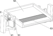
Fig. 6 is a schematic perspective view of the guiding device of the present invention.
Fig. 7 is an enlarged view of part C of the present invention.
Fig. 8 is a schematic perspective view of a vibration device according to the present invention.
Fig. 9 is an enlarged view of the portion D of the present invention.
Fig. 10 is an enlarged view of part E of the present invention.
Fig. 11 is a schematic perspective view of the sweeping device of the present invention.
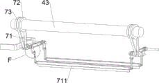
Fig. 12 is an enlarged view of part F of the present invention.
Fig. 13 is a schematic perspective view of the refining apparatus of the present invention.
Fig. 14 is an enlarged view of part G of the present invention.
Fig. 15 is a schematic perspective view of the collecting device of the present invention.
In the reference symbols: 1_ base, 2_ mounting, 21_ mounting plate, 3_ crushing wheel, 4_ crushing device, 41_ driving motor, 42_ crushing box, 43_ first rotating shaft, 44_ gear, 45_ striker tooth, 5_ guide device, 51_ fixed groove plate, 52_ movable inclined plate, 53_ filter screen, 54_ first spring, 6_ vibrator, 61_ second rotating shaft, 62_ first belt pulley, 63_ first flat belt, 64_ magnetic rotating groove plate, 65_ magnetic rotating plate, 66_ arc groove plate, 67_ second spring, 68_ circular slider, 7_ sweeping device, 71_ third rotating shaft, 72_ second belt pulley, 73_ second flat belt pulley, 74_ third belt pulley, 75_ third flat belt, 76_ rotating rod, 77_ fourth rotating shaft, 78_ swinging sleeve rod, 79_ third spring, 710_ connecting rod, 711_ sweeping rod, 8_ refining device, 81_ fixed jaw, 82_ cylinder, 83_ slide rail, 84_ fixed slide block, 85_ movable jaw plate, 9_ collecting device, 91_ arc-shaped blanking channel, 92_ blanking hopper and 93_ collecting box.
Detailed Description
The invention is described in detail below with reference to the figures and the embodiments.
Example 1
The utility model provides a limestone breaker for building, as shown in fig. 1-10, including base 1, mounting bracket 2, mounting panel 21, broken wheel 3, stirring device 4, guider 5 and vibrator 6, be equipped with mounting bracket 2 between the base 1 top right side of both sides around, base 1 top left side all is equipped with mounting panel 21, be equipped with stirring device 4 between mounting panel 21 upper portion, be equipped with two broken wheels 3 on the stirring device 4, be equipped with guider 5 between the mounting panel 21 middle part, be equipped with vibrator 6 between guider 5 and the stirring device 4.
Stirring device 4 is including driving motor 41, stir garrulous box 42, first pivot 43, gear 44 and fender material tooth 45, the mounting panel 21 upper portion of front side is equipped with driving motor 41, be equipped with between the inboard upper portion of mounting panel 21 and stir garrulous box 42, stir the equal rotary type in the inside left and right sides of garrulous box 42 and be equipped with first pivot 43, crushing wheel 3 all is connected with the first pivot 43 of homonymy, left first pivot 43 and driving motor 41 output shaft, first pivot 43 front side all is equipped with gear 44, gear 44 intermeshing, stir the left and right sides middle part of garrulous box 42 inner wall and all be equipped with and keep off material tooth 45, keep off material tooth 45 and the cooperation of crushing wheel 3.
The guide device 5 comprises fixed groove plates 51, movable inclined plates 52, a filter screen 53 and first springs 54, the fixed groove plates 51 are symmetrically arranged in the middle of the inner side of the mounting plate 21 in a bilateral mode, the number of the fixed groove plates 51 is 4, the movable inclined plates 52 are slidably arranged between the fixed groove plates 51, the filter screen 53 is arranged on the right sides of the movable inclined plates 52, and the first springs 54 are arranged between the movable inclined plates 52 and the fixed groove plates 51.
The vibration device 6 comprises a second rotating shaft 61, a first belt pulley 62, a first flat belt 63, a magnetic rotating groove plate 64, a magnetic rotating plate 65, an arc-shaped groove plate 66, a second spring 67 and a circular sliding block 68, wherein the middle part of the inner side of the mounting plate 21 is rotatably provided with the second rotating shaft 61, the front side and the rear side of the first rotating shaft 43 at the middle part and the right side of the second rotating shaft 61 are respectively provided with the first belt pulley 62, the number of the first belt pulleys 62 is 4, the first flat belt 63 is wound between the two first belt pulleys 62 at the same side, the inner side of the second rotating shaft 61 is provided with the magnetic rotating plate 65, the arc-shaped groove plate 66 is arranged between the tops of the two fixed groove plates 51 at the same side, the circular sliding block 68 is arranged in the arc-shaped groove plate 66 in a sliding manner, the outer side of the circular sliding block 68 is provided with the magnetic rotating groove plate 64, the magnetic rotating groove plate 64 is rotatably connected with the second rotating shaft 61 at the same side, and the magnetic rotating groove plate 64 is matched with the magnetic rotating plate 65, a second spring 67 is arranged between the left side of the circular slide block 68 and the arc-shaped groove plate 66 on the same side.
When people need to crush limestone, firstly, the limestone is put into the crushing box body 42, then the driving motor 41 is started, the output shaft of the driving motor 41 drives the first rotating shaft 43 on the left side to rotate, the first rotating shaft 43 on the right side is driven by the gear 44 to rotate, the crushing wheel 3 is driven by the first rotating shaft 43 to rotate, the limestone is crushed by the crushing wheel 3, the material blocking teeth 45 play an auxiliary role, the crushed limestone falls down to the movable inclined plate 52, meanwhile, the first rotating shaft 43 on the right side drives the first belt pulley 62, the first flat belt 63 and the second rotating shaft 61 to rotate, the second rotating shaft 61 drives the magnetic rotating plate 65 to rotate, when the magnetic rotating plate 65 is close to the magnetic rotating groove plate 64, magnetic force is generated to drive the magnetic rotating groove plate 64 to rotate, so as to drive the circular slide block 68 to slide in the arc-shaped groove plate 66, the second spring 67 is compressed, and simultaneously, the magnetic rotating groove plate 64 drives the movable inclined plate 52 to move downwards, the first spring 54 is compressed, when the second spring 67 can not be compressed, the magnetic rotating groove plate 64 stops rotating, the magnetic rotating plate 65 continues rotating, the magnetic rotating plate 65 is far away from the magnetic rotating groove plate 64, the magnetic force disappears, the second spring 67 restores to the original state, the round slide block 68 is driven to slide and reset, so that the magnetic rotating groove plate 64 is driven to rotate reversely and reset, meanwhile, the first spring 54 restores to the original state, the movable inclined plate 52 is driven to move upwards and reset, the movable inclined plate 52 and the filter screen 53 reciprocate up and down, the crushed limestone slides to the right, the smaller limestone falls down through the filter screen 53, the larger limestone continues to slide to the right, then the smaller limestone and the larger limestone are respectively collected manually, the larger limestone can be put into the crushing box 42 again for crushing, the device operates repeatedly, when all the limestone is crushed, the drive motor 41 may be turned off.
Example 2
On the basis of embodiment 1, as shown in fig. 1, 2, 11, 12, 13, 14 and 15, the material sweeping device 7 is further included, the material sweeping device 7 includes a third rotating shaft 71, a second pulley 72, a second flat belt 73, a third pulley 74, a third flat belt 75, a rotating rod 76, a fourth rotating shaft 77, a swinging sleeve 78, a third spring 79, a connecting rod 710 and a material sweeping rod 711, the upper portion of the inner side of the mounting plate 21 is provided with the third rotating shaft 71 in a left-right symmetric rotating manner, the middle portion of the third rotating shaft 71 on the left side and the front and rear sides of the first rotating shaft 43 on the left side are provided with the second pulley 72, the number of the second pulleys 72 is 4, the second flat belt 73 is wound between the two second pulleys 72 on the same side, the third pulley 74 is provided on the inner side of the third rotating shaft 71, the third belt 75 is wound between the two third pulleys 74 on the same side, the rotating rod 76 is provided on the inner side of the third rotating shaft 71, the rotating rod 76 is located on the inner side of the third belt pulley 74, the lower portion of the inner side of the rotating rod 76 is provided with a fourth rotating shaft 77, the inner sides of the fourth rotating shafts 77 are rotatably provided with swing loop bars 78, the lower portions of the swing loop bars 78 are provided with connecting rods 710 in a sliding manner, third springs 79 are arranged between the connecting rods 710 and the swing loop bars 78 on the same side, the left side and the right side of the lower portion of the crushing box body 42 are provided with sweeping rods 711 in a sliding manner, and the sweeping rods 711 are rotatably connected with the lower portions of the two connecting rods 710 on the same side.
When the first rotating shaft 43 on the left side rotates, the third rotating shaft 71 on the left side is driven to rotate by the second flat belt 73 and the second belt pulley 72, the third rotating shaft 71 on the right side is driven to rotate by the third flat belt 75 and the third belt pulley 74, the rotating rod 76 and the fourth rotating shaft 77 are driven to rotate by the third rotating shaft 71, the rotating rod 76 drives the material sweeping rod 711 to reciprocate up and down by the swinging sleeve rod 78 and the connecting rod 710, the third spring 79 deforms adaptively, so that the material sweeping rod 711 cleans the lower part of the inner wall of the crushing box 42, lime stained on the lower part of the inner wall of the crushing box 42 is swept down, and when the first rotating shaft 43 on the left side stops rotating, all the rotating is stopped.
Still refine device 8 including fixed hubei province board 81, the cylinder 82, slide rail 83, gu fixed sliding block 84 and activity hubei province board 85, be equipped with fixed hubei province board 81 between the side in base 1 upper portion, be equipped with cylinder 82 in the middle of the 2 upper portions of mounting bracket, base 1 upper portion middle part front and back symmetry is equipped with slide rail 83, slide rail 83 is located fixed hubei province board 81 right side, it is equipped with fixed sliding block 84 all to slide on the slide rail 83, be equipped with activity hubei province board 85 between the fixed sliding block 84 inboard, activity hubei province board 85 is the tilt state, activity hubei province board 85 cooperates with fixed hubei province board 81, activity hubei province board 85 is connected with the left side of cylinder 82 telescopic link.
When the larger limestone continuously slides to the right, the larger limestone can fall between the fixed jaw plate 81 and the movable jaw plate 85, people can start the air cylinder 82 to control the telescopic rod of the air cylinder 82 to extend and shorten in a reciprocating manner, so that the movable jaw plate 85 is driven to reciprocate left and right, the larger limestone is crushed under the cooperation of the fixed jaw plate 81, the crushed limestone falls downwards and is collected manually, and after all the limestone is crushed, the air cylinder 82 is closed.
Still including collection device 9, collection device 9 is equipped with arc unloading passageway 91 between the inboard lower part of mounting panel 21 including arc unloading passageway 91, lower hopper 92 and collecting box 93, and arc unloading passageway 91 is located under the filter screen 53, is equipped with lower hopper 92 between the middle side in base 1 upper portion, and lower hopper 92 is located fixed hubei province board 81 below, has placed collecting box 93 between the left side in base 1 upper portion, and collecting box 93 is located arc unloading passageway 91 and lower hopper 92 below.
When smaller limestone falls down through the filter screen 53, the smaller limestone falls down into the collecting box 93 through the arc-shaped blanking channel 91, when the movable jaw plate 85 and the fixed jaw plate 81 crush larger limestone, the crushed limestone falls down and falls into the collecting box 93 through the blanking hopper 92, after all the limestone is crushed, the collecting box 93 is taken away manually, then the limestone in the collecting box 93 is taken out, and finally the collecting box 93 is put back to the original position.
The above description is only an embodiment of the present invention, and not intended to limit the scope of the present invention, and all modifications of equivalent structures and equivalent processes, which are made by the present specification, or directly or indirectly applied to other related technical fields, are included in the scope of the present invention.
Claims (8)
1. A limestone crusher for construction is characterized by comprising:
the mounting rack (2) is arranged between the top sides of the two sides of the base (1);
the mounting plate (21), the mounting plate (21) is mounted on one side of the top of the base (1) far away from the mounting frame (2);
the stirring device (4), the stirring device (4) is arranged between the upper parts of the mounting plates (21);
the crushing wheel (3), the crushing wheel (3) is installed on the crushing device (4);
the guide device (5), the guide device (5) is installed between the middle parts of the mounting plates (21);
the vibrating device (6) is arranged between the guide device (5) and the crushing device (4).
2. Limestone crusher for buildings according to claim 1, characterized in that the crushing means (4) comprise:
the driving motor (41), the driving motor (41) is installed on the upper part of the mounting plate (21) on one side;
the stirring box body (42), the stirring box body (42) is arranged between the upper parts of the inner sides of the mounting plates (21);
the first rotating shaft (43) is rotatably arranged in the mincing box body (42), the crushing wheels (3) are connected with the first rotating shaft (43) on the same side, and the first rotating shaft (43) on one side is connected with an output shaft of the driving motor (41);
the gear (44), the gear (44) is installed on one side of the first rotating shaft (43), and the gears (44) are meshed with each other;
keep off material tooth (45), keep off material tooth (45) symmetry and install in the middle part of stirring crushing box (42) inner wall both sides, keep off material tooth (45) and crushing wheel (3) cooperation.
3. Limestone crusher for construction according to claim 2, characterized in that the guide means (5) comprise:
the fixed slotted plates (51), the fixed slotted plates (51) are symmetrically arranged in the middle of the inner side of the mounting plate (21);
the movable inclined plates (52), the movable inclined plates (52) are slidably arranged between the fixed groove plates (51);
the filter screen (53), the filter screen (53) is installed on one side of the movable sloping plate (52);
and the first spring (54), and the first spring (54) is arranged between the movable inclined plate (52) and the fixed groove plate (51).
4. A limestone crusher for buildings according to claim 3, characterized in that the vibrating device (6) comprises:
the second rotating shaft (61), the second rotating shaft (61) is rotatably installed in the middle of the inner side of the installation plate (21);
the number of the first belt pulleys (62) is at least two, and the first belt pulleys (62) are respectively arranged at the middle part of the second rotating shaft (61) and at two sides of the first rotating shaft (43) at the other side;
a first flat belt (63), wherein the first flat belt (63) is wound between two first belt pulleys (62) on the same side;
the magnetic rotating plate (65), the magnetic rotating plate (65) is arranged on the inner side of the second rotating shaft (61);
the arc-shaped slotted plate (66), the arc-shaped slotted plate (66) is installed between the tops of the two fixed slotted plates (51) on the same side;
the round sliding block (68), the round sliding block (68) is installed in the arc-shaped groove plate (66) in a sliding way;
the magnetic rotating groove plate (64) is arranged on the outer side of the circular sliding block (68), the magnetic rotating groove plate (64) is rotatably connected with the second rotating shaft (61) on the same side, and the magnetic rotating groove plate (64) is matched with the magnetic rotating plate (65);
and the second spring (67) is arranged between one side of the circular sliding block (68) and the arc-shaped groove plate (66) on the same side.
5. Limestone crusher for buildings according to claim 4, characterized in that it further comprises a sweeping device (7), the sweeping device (7) comprising:
the third rotating shaft (71), the third rotating shaft (71) is symmetrically and rotatably arranged on the upper part of the inner side of the mounting plate (21);
the number of the second belt pulleys (72) is at least two, and the second belt pulleys (72) are respectively arranged in the middle of the third rotating shaft (71) on one side and on two sides of the first rotating shaft (43) on one side;
the second flat belt (73), the second flat belt (73) is wound between two second pulleys (72) on the same side;
a third belt pulley (74), wherein the third belt pulley (74) is arranged on the inner side of the third rotating shaft (71);
a third belt (75), the third belt (75) is wound between two third belt pulleys (74) on the same side;
the rotating rod (76), the rotating rod (76) is installed on the inner side of the third rotating shaft (71), and the rotating rod (76) is located on the inner side of the third belt pulley (74);
the fourth rotating shaft (77), the fourth rotating shaft (77) is installed at the lower part of the inner side of the rotating rod (76);
the swing loop bar (78), the swing loop bar (78) is installed on the inner side of the fourth rotating shaft (77) in a rotating way;
the connecting rod (710), the connecting rod (710) is installed on the lower part of the swing loop bar (78) in a sliding way;
a third spring (79), the third spring (79) being mounted between the connecting rod (710) and the swing link (78);
the sweeping rod (711), the sweeping rod (711) is slidably installed at two sides of the lower part of the crushing box body (42), and the sweeping rod (711) is rotatably connected with the lower parts of the two connecting rods (710) at the same side.
6. The limestone crusher for construction according to claim 5, characterized in that it further comprises a refining device (8), the refining device (8) comprising:
the fixed jaw plate (81), the fixed jaw plate (81) is arranged between the middle sides of the upper parts of the bases (1);
the air cylinder (82), the air cylinder (82) is installed in the middle of the upper part of the mounting frame (2);
the sliding rails (83) are symmetrically arranged on the upper middle side of the base (1), and the sliding rails (83) are positioned on one side of the fixed jaw plate (81);
the fixed sliding block (84), the fixed sliding block (84) is installed on the sliding rail (83) in a sliding way;
the movable jaw plate (85) is arranged between the inner sides of the fixed sliding blocks (84), the movable jaw plate (85) is matched with the fixed jaw plate (81), and the movable jaw plate (85) is connected with an expansion rod of the cylinder (82).
7. Limestone crusher for buildings according to claim 6, characterized in that it further comprises collecting means (9), the collecting means (9) comprising:
the arc-shaped blanking channel (91), the arc-shaped blanking channel (91) is arranged between the lower parts of the inner sides of the mounting plates (21), and the arc-shaped blanking channel (91) is positioned right below the filter screen (53);
the lower hopper (92), the lower hopper (92) is installed between the middle sides of the upper parts of the bases (1), and the lower hopper (92) is positioned below the fixed jaw plate (81);
the collecting box (93), collecting box (93) are placed between base (1) upper portion one side, and collecting box (93) are located arc unloading passageway (91) and hopper (92) below.
8. The limestone crusher for building according to claim 6, wherein the movable jaw (85) is inclined so as to be able to fix the limestone with the fixed jaw (81).
Priority Applications (1)
| Application Number | Priority Date | Filing Date | Title |
|---|---|---|---|
| CN202110919236.5A CN113600279A (en) | 2021-08-11 | 2021-08-11 | Limestone crusher for building |
Applications Claiming Priority (1)
| Application Number | Priority Date | Filing Date | Title |
|---|---|---|---|
| CN202110919236.5A CN113600279A (en) | 2021-08-11 | 2021-08-11 | Limestone crusher for building |
Publications (1)
| Publication Number | Publication Date |
|---|---|
| CN113600279A true CN113600279A (en) | 2021-11-05 |
Family
ID=78308202
Family Applications (1)
| Application Number | Title | Priority Date | Filing Date |
|---|---|---|---|
| CN202110919236.5A Pending CN113600279A (en) | 2021-08-11 | 2021-08-11 | Limestone crusher for building |
Country Status (1)
| Country | Link |
|---|---|
| CN (1) | CN113600279A (en) |
Cited By (2)
| Publication number | Priority date | Publication date | Assignee | Title |
|---|---|---|---|---|
| CN114653447A (en) * | 2022-03-17 | 2022-06-24 | 郑海涛 | Turning softening type lime pre-crusher for aquaculture |
| CN115228540A (en) * | 2022-07-13 | 2022-10-25 | 崔懿帆 | Double-station stone crushing device and method for building construction |
Citations (8)
| Publication number | Priority date | Publication date | Assignee | Title |
|---|---|---|---|---|
| JPH11287593A (en) * | 1998-03-31 | 1999-10-19 | Nippon Haa Kk | Apparatus for scraping stuck object on heat transfer plate surface in heat exchanger |
| US20170100754A1 (en) * | 2015-10-08 | 2017-04-13 | Pneumat Systems, Inc. | Counter-rotational dual whip-head device for fragmenting solidified bulk materials in containment vessels |
| CN208359079U (en) * | 2018-04-20 | 2019-01-11 | 邯郸金隅太行商砼科技有限公司 | A kind of blender for concrete mixing plant |
| CN110695264A (en) * | 2019-11-18 | 2020-01-17 | 周鸿林 | Adjustable resistor two-end pin cutting device for computer production |
| CN210115134U (en) * | 2019-04-18 | 2020-02-28 | 广西友信矿业有限公司 | Ore crushing device |
| CN110935506A (en) * | 2019-12-12 | 2020-03-31 | 江西桔王药业有限公司 | Superfine grinder of medicine |
| CN213134008U (en) * | 2020-09-03 | 2021-05-07 | 张建文 | Grit screening machine that makes an uproar falls gives sound insulation |
| CN113042361A (en) * | 2021-04-29 | 2021-06-29 | 成渝钒钛科技有限公司 | Blanking screening device of cloth bag dust removal scraper conveyor for furnace trough and using method of blanking screening device |
-
2021
- 2021-08-11 CN CN202110919236.5A patent/CN113600279A/en active Pending
Patent Citations (8)
| Publication number | Priority date | Publication date | Assignee | Title |
|---|---|---|---|---|
| JPH11287593A (en) * | 1998-03-31 | 1999-10-19 | Nippon Haa Kk | Apparatus for scraping stuck object on heat transfer plate surface in heat exchanger |
| US20170100754A1 (en) * | 2015-10-08 | 2017-04-13 | Pneumat Systems, Inc. | Counter-rotational dual whip-head device for fragmenting solidified bulk materials in containment vessels |
| CN208359079U (en) * | 2018-04-20 | 2019-01-11 | 邯郸金隅太行商砼科技有限公司 | A kind of blender for concrete mixing plant |
| CN210115134U (en) * | 2019-04-18 | 2020-02-28 | 广西友信矿业有限公司 | Ore crushing device |
| CN110695264A (en) * | 2019-11-18 | 2020-01-17 | 周鸿林 | Adjustable resistor two-end pin cutting device for computer production |
| CN110935506A (en) * | 2019-12-12 | 2020-03-31 | 江西桔王药业有限公司 | Superfine grinder of medicine |
| CN213134008U (en) * | 2020-09-03 | 2021-05-07 | 张建文 | Grit screening machine that makes an uproar falls gives sound insulation |
| CN113042361A (en) * | 2021-04-29 | 2021-06-29 | 成渝钒钛科技有限公司 | Blanking screening device of cloth bag dust removal scraper conveyor for furnace trough and using method of blanking screening device |
Non-Patent Citations (1)
| Title |
|---|
| 武丽梅: "《机械原理》", 31 August 2015 * |
Cited By (2)
| Publication number | Priority date | Publication date | Assignee | Title |
|---|---|---|---|---|
| CN114653447A (en) * | 2022-03-17 | 2022-06-24 | 郑海涛 | Turning softening type lime pre-crusher for aquaculture |
| CN115228540A (en) * | 2022-07-13 | 2022-10-25 | 崔懿帆 | Double-station stone crushing device and method for building construction |
Similar Documents
| Publication | Publication Date | Title |
|---|---|---|
| CN113600279A (en) | Limestone crusher for building | |
| CN112934375A (en) | Construction waste grading crushing equipment | |
| CN107138213B (en) | A kind of building stones crushing device | |
| CN113000132B (en) | Energy-saving environment-friendly household garbage crushing treatment device | |
| CN113019557A (en) | Ceramic manufacture waste recovery device | |
| CN115156032B (en) | Energy-saving and environment-friendly screening device for building material sand stone for building engineering construction | |
| CN113695221B (en) | Novel energy-saving environment-friendly sand and stone screening equipment | |
| CN214599341U (en) | Civil engineering construction waste smashes recovery processing device | |
| CN211660219U (en) | Thermal power plant ash treatment device that practicality is strong | |
| CN212348390U (en) | Mobile stirring device for building construction | |
| CN212040673U (en) | Vertical pair roller sand making machine | |
| CN211612992U (en) | Impact type fine crushing device for limestone ore | |
| CN209465321U (en) | A kind of metallurgy vibrating screen | |
| CN219232529U (en) | Grinding and powder selecting integrated machine for building materials | |
| CN219923089U (en) | Cement production crushing and grinding equipment | |
| CN217568909U (en) | Stone powder processing mechanism with good grinding effect | |
| CN115414993B (en) | A reducing mechanism for bentonite processing | |
| CN218078108U (en) | Pottery china clay refines device | |
| CN211487816U (en) | Jaw type crushing and recycling device for waste stone materials for road and bridge construction | |
| CN219663837U (en) | Chemical industry breaker | |
| CN217368571U (en) | Broken sieving mechanism of high-efficient kibbling recycled concrete | |
| CN220559356U (en) | Quartz sand crushing and grinding device | |
| CN214439503U (en) | Raw material pulverizer for building engineering concrete processing | |
| CN215140204U (en) | Reducing mechanism is used in stone material processing | |
| CN219051442U (en) | A reducing mechanism for rare earth ore processing |
Legal Events
| Date | Code | Title | Description |
|---|---|---|---|
| PB01 | Publication | ||
| PB01 | Publication | ||
| SE01 | Entry into force of request for substantive examination | ||
| SE01 | Entry into force of request for substantive examination | ||
| RJ01 | Rejection of invention patent application after publication |
Application publication date: 20211105 |
|
| RJ01 | Rejection of invention patent application after publication |