CN113547110A - Automatic control system of baking oven - Google Patents
Automatic control system of baking oven Download PDFInfo
- Publication number
- CN113547110A CN113547110A CN202110732884.XA CN202110732884A CN113547110A CN 113547110 A CN113547110 A CN 113547110A CN 202110732884 A CN202110732884 A CN 202110732884A CN 113547110 A CN113547110 A CN 113547110A
- Authority
- CN
- China
- Prior art keywords
- module
- control
- combustion
- gas
- combustion air
- Prior art date
- Legal status (The legal status is an assumption and is not a legal conclusion. Google has not performed a legal analysis and makes no representation as to the accuracy of the status listed.)
- Granted
Links
- 238000002485 combustion reaction Methods 0.000 claims abstract description 86
- 238000001514 detection method Methods 0.000 claims abstract description 49
- 238000012544 monitoring process Methods 0.000 claims abstract description 41
- 239000002737 fuel gas Substances 0.000 claims abstract description 7
- 239000007789 gas Substances 0.000 claims description 93
- 230000001105 regulatory effect Effects 0.000 claims description 27
- 239000003638 chemical reducing agent Substances 0.000 claims description 11
- 238000010438 heat treatment Methods 0.000 claims description 11
- 230000000007 visual effect Effects 0.000 claims description 9
- 230000001276 controlling effect Effects 0.000 claims description 8
- 238000004321 preservation Methods 0.000 claims description 7
- 238000002955 isolation Methods 0.000 claims description 4
- 239000011241 protective layer Substances 0.000 claims description 4
- 230000000149 penetrating effect Effects 0.000 claims description 3
- MWUXSHHQAYIFBG-UHFFFAOYSA-N nitrogen oxide Inorganic materials O=[N] MWUXSHHQAYIFBG-UHFFFAOYSA-N 0.000 description 12
- 238000000034 method Methods 0.000 description 7
- 239000000446 fuel Substances 0.000 description 6
- 229910000831 Steel Inorganic materials 0.000 description 5
- 239000010959 steel Substances 0.000 description 5
- 230000005611 electricity Effects 0.000 description 4
- IJGRMHOSHXDMSA-UHFFFAOYSA-N Atomic nitrogen Chemical compound N#N IJGRMHOSHXDMSA-UHFFFAOYSA-N 0.000 description 3
- 238000012423 maintenance Methods 0.000 description 3
- 239000002699 waste material Substances 0.000 description 3
- UGFAIRIUMAVXCW-UHFFFAOYSA-N Carbon monoxide Chemical compound [O+]#[C-] UGFAIRIUMAVXCW-UHFFFAOYSA-N 0.000 description 2
- 230000005540 biological transmission Effects 0.000 description 2
- 239000003546 flue gas Substances 0.000 description 2
- 239000012535 impurity Substances 0.000 description 2
- 239000011819 refractory material Substances 0.000 description 2
- 239000002912 waste gas Substances 0.000 description 2
- 230000009286 beneficial effect Effects 0.000 description 1
- 238000010586 diagram Methods 0.000 description 1
- 229910001873 dinitrogen Inorganic materials 0.000 description 1
- 238000005259 measurement Methods 0.000 description 1
- 238000012986 modification Methods 0.000 description 1
- 230000004048 modification Effects 0.000 description 1
- 229910052757 nitrogen Inorganic materials 0.000 description 1
- 238000011165 process development Methods 0.000 description 1
- 238000010926 purge Methods 0.000 description 1
- 238000010792 warming Methods 0.000 description 1
Images


Classifications
-
- B—PERFORMING OPERATIONS; TRANSPORTING
- B22—CASTING; POWDER METALLURGY
- B22D—CASTING OF METALS; CASTING OF OTHER SUBSTANCES BY THE SAME PROCESSES OR DEVICES
- B22D41/00—Casting melt-holding vessels, e.g. ladles, tundishes, cups or the like
- B22D41/005—Casting melt-holding vessels, e.g. ladles, tundishes, cups or the like with heating or cooling means
- B22D41/01—Heating means
- B22D41/015—Heating means with external heating, i.e. the heat source not being a part of the ladle
-
- B—PERFORMING OPERATIONS; TRANSPORTING
- B22—CASTING; POWDER METALLURGY
- B22D—CASTING OF METALS; CASTING OF OTHER SUBSTANCES BY THE SAME PROCESSES OR DEVICES
- B22D46/00—Controlling, supervising, not restricted to casting covered by a single main group, e.g. for safety reasons
Landscapes
- Engineering & Computer Science (AREA)
- Mechanical Engineering (AREA)
- Waste-Gas Treatment And Other Accessory Devices For Furnaces (AREA)
Abstract
The invention discloses an automatic control system of a baking oven, which comprises an oven body and an electric control cabinet, wherein a connecting loop is also arranged between the oven body and the electric control cabinet and comprises an end cover lifting power unit, a combustion-supporting air supply and control unit, a fuel gas supply and control unit, a combustion working condition control and real-time monitoring unit and a pressure detection unit, the end cover lifting power unit comprises a driving assembly and a driving control module for controlling and driving the end cover to lift, a PLC (programmable logic controller) is arranged in the electric control cabinet, the driving control module, the combustion-supporting air monitoring module, the fuel gas supply control module, the baking module, the pressure detection module and the temperature detection module are all integrated in the PLC, a power module connected with the PLC is also arranged in the electric control cabinet, the automatic control system of the baking oven carries out detection and data signal feedback on various indexes of the baking oven through the PLC, and realizes the intelligent operation of the baking oven, the visualized parameter data display and intelligent control improve the safety and the practicability of the equipment.
Description
Technical Field
The invention belongs to the technical field of baking ovens, and particularly relates to an automatic control system of a baking oven.
Background
The traditional metallurgical baking furnace has huge structure and integral operation, once equipment fails, the whole equipment needs to be overhauled, the overhauling engineering is huge, the great labor cost and time cost are consumed, the traditional metallurgical baking furnace for steel ladles basically and completely adopts a mode of manually opening and closing a gate valve, the mode wastes time and labor, great potential safety hazard exists, reasonable and effective intelligent automatic on-off of a combustion air pipeline and a gas pipeline cannot be realized, real-time intelligent flow regulation cannot be performed on the combustion air pipeline and the gas pipeline, further, the traditional metallurgical baking furnace tank cover is heavy, the steel ladles cannot be conveniently opened for lifting, the operation is not stable enough during the equipment operation, the failure rate is high, the maintenance is not convenient, and meanwhile, data such as pressure detection, switch structure, temperature detection and the like of each equipment pipeline cannot be visually presented, the data recording and the checking of operating personnel are very inconvenient, the intelligent operation on the baking oven cannot be realized, the operation execution hysteresis quality to a certain degree exists, and the great potential safety hazard also exists.
Disclosure of Invention
The invention aims to provide an automatic control system of a baking oven to solve the existing problems, the equipment carries out detection and data signal feedback of multiple indexes on the baking oven through a PLC controller, realizes an intelligent operation mode of the baking oven, saves time and labor, and realizes intuitive parameter data display and intelligent control, thereby greatly improving the safety and the practicability of the equipment.
The technical scheme adopted by the invention is as follows:
an automatic control system of a baking furnace comprises a furnace body and an electric control cabinet, wherein a connecting loop is also arranged between the furnace body and the electric control cabinet and comprises an end cover lifting power unit, a combustion-supporting air supply and control unit, a fuel gas supply and control unit, a combustion working condition control and real-time monitoring unit and a pressure detection unit, the end cover lifting power unit comprises a driving component arranged on the furnace body and a driving control module used for controlling and driving the end cover to lift, the driving component comprises an end cover arranged at the upper end of the furnace body, a crank rocker arm used for fixedly connecting the end cover to lift, a rotating shaft penetrating through the tail end of the crank rocker arm and vertically arranged, and a motor connected with the rotating shaft, and the motor is electrically connected with the driving control module;
the combustion-supporting air supply and control unit comprises a combustion-supporting air structure and a combustion-supporting air monitoring module, the combustion-supporting air structure is connected and installed in the furnace body, the combustion-supporting air monitoring module is used for monitoring the supply of combustion-supporting air, flow regulation and data signal feedback and control, the combustion-supporting air structure comprises a combustion-supporting air pipeline leading into the furnace body, a high-pressure fan arranged on the combustion-supporting air pipeline and a first electromagnetic regulating valve installed on the combustion-supporting air pipeline, and the high-pressure fan and the first electromagnetic regulating valve are respectively and electrically connected with the combustion-supporting air monitoring module;
the gas supply and control unit comprises a gas supply assembly leading into the furnace body and a gas supply control module used for monitoring gas supply, flow regulation and data signal feedback and control, wherein the gas supply assembly comprises a gas pipeline arranged in the furnace body, a gas filter arranged on the gas pipeline, a pneumatic quick cut-off valve arranged on the gas pipeline and positioned on the left side of the gas filter, a second electromagnetic regulating valve arranged on the left side of the pneumatic quick cut-off valve and a blow-off valve arranged on the gas pipeline, and the gas supply control module is respectively electrically connected with the gas filter, the pneumatic quick cut-off valve and the second electromagnetic regulating valve;
the combustion condition control and real-time monitoring unit comprises a combustion chamber arranged in the furnace body, a UV detector arranged in the combustion chamber and used for monitoring combustion flame and a baking module used for detecting the combustion condition in the combustion chamber and controlling different combustion modes, the UV detector is connected with the pneumatic quick cut-off valve, the pressure detection unit comprises a pressure detection sensor for detecting the pressure of a gas pipeline and the pressure of a combustion air pipeline and a pressure detection module for monitoring the gas supply pressure, the combustion air supply pressure and data signal feedback and control, the pressure detection sensor is electrically connected with the pressure detection module, the furnace body is also internally provided with a temperature detector which is electrically connected with the temperature detector and feeds back a real-time signal, and the temperature detector is electrically connected with the temperature detection module;
the electric control cabinet is internally provided with a PLC controller, the driving control module, the combustion air monitoring module, the fuel gas supply control module, the baking module, the pressure detection module and the temperature detection module are all integrally arranged in the PLC controller, and the electric control cabinet is internally provided with a power supply module connected with the PLC controller.
Preferably, the output end of the motor is further connected with a speed reducer, the speed reducer and the rotating shaft are further provided with a hydraulic band-type brake, and the speed reducer and the hydraulic band-type brake are respectively electrically connected with the PLC.
Preferably, the baking module comprises a conventional baking mode, a rapid heating mode and a small fire heat preservation mode, and the baking module is electrically connected with the first electromagnetic regulating valve and the second electromagnetic regulating valve respectively.
Further preferably, a spare manual switch gate valve and a spare manual regulating valve are arranged on the combustion air pipeline and the gas pipeline.
Preferably, the combustion condition control and real-time monitoring unit and the pressure detection unit are both provided with audible and visual alarms, and the audible and visual alarms are electrically connected with the PLC.
Preferably, the electric control cabinet is an explosion-proof electric control cabinet, and an insulating protective layer is arranged on the outer surface of the electric control cabinet.
Preferably, a touch display screen connected with the PLC controller is further disposed on the surface of the electric control cabinet.
Further preferably, the power module in the electric control cabinet comprises a 380V alternating current power supply, a stabilized voltage power supply connected with the alternating current power supply and an isolated power supply connected with the stabilized voltage power supply.
Preferably, an electronic ignition gun is further arranged in the combustion chamber of the furnace body through a support, and the electronic ignition gun is electrically connected with the PLC.
Preferably, the temperature detector comprises a temperature thermocouple and a compensation lead connected with the temperature thermocouple.
In summary, due to the adoption of the technical scheme, the invention has the beneficial effects that:
1. in the invention, an end cover lifting power unit is arranged: the automatic ignition device is composed of a motor, a speed reducer, a hydraulic band-type brake and the like, the parts provide power for a baking system and drive a crank rocker arm to rotate, so that an end cover can be freely opened, the maximum inclination angle can reach 85 degrees, ladle lifting is facilitated, the structure is safe and reliable and operates stably, space is greatly saved, faults are reduced, and maintenance is facilitated;
2. according to the invention, a combustion-supporting air supply and control unit is arranged, the combustion-supporting air supply and control unit comprises a high-pressure fan, an electromagnetic regulating valve, a manual regulating valve and the like, the warming and baking of the preheating of the ladle are met according to the characteristics of the fan and the automatic regulation of valves, the intelligent control of the structure is realized through intelligent automatic control and standby manual operation control, the intelligent control of the structure is realized, the gas supply is automatically cut off when the rapid cut-off valve is in an accidental situation such as power grid disconnection, low gas pressure or large fluctuation range and the like by arranging a gas filter, a manual switch gate valve, a pressure detection sensor, a pneumatic rapid cut-off valve, the electromagnetic regulating valve, a blow-down valve and the like, and the gas filter can filter out moisture and impurities in the gas so as to ensure the continuous and stable combustion of the gas;
3. in the invention, the combustion condition is monitored in real time by arranging the combustion condition control and real-time monitoring unit, when the UV detector can not detect the flame, a signal is transmitted to the pneumatic quick cut-off valve, the device automatically cuts off the gas supply, performs nitrogen purging, and gives out acousto-optic alarm, by arranging the pressure detection sensor for detecting the pressure of the gas pipeline and the pressure of the combustion air pipeline, the pressure value of the pressure detection sensor can visually display the real-time pressure of the gas and the combustion air on the touch display screen, when the pressure is too low or the fluctuation is too large, the sound-light alarm is sent out, the corresponding control valve is cut off, and the structure consisting of a temperature thermocouple, a compensation wire and the like is arranged, so that the dynamic measurement and control of the temperature of the baking oven in the whole process are realized, and performing visual display, and adjusting the delivery volume of fuel gas and air in real time according to the temperature in the baking oven;
4. according to the invention, the power supply capacity of a 380V alternating current power supply is reasonably selected according to the electricity consumption of the electricity, the instruments and the machinery, an isolation power supply and a stabilized voltage supply are arranged, the normal operation of the electricity, the instruments and the machinery is ensured, and short circuit and overload protection are carried out on a loop; the PLC integrated structure is set through signal acquisition and feedback of a primary instrument on site, and the drive control module is used for controlling and driving the end cover to lift; the combustion air monitoring module is used for monitoring the supply of combustion air, flow regulation and data signal feedback and control; the gas supply control module is used for monitoring gas supply, flow regulation and data signal feedback and control; the system comprises a baking module, a heating module and a control module, wherein the baking module is used for detecting the combustion condition in a combustion chamber and controlling different combustion modes, different baking curves are respectively arranged in the system according to requirements, each curve respectively corresponds to different heating requirements, such as conventional baking, rapid heating, small fire heat preservation and the like, during operation, only a corresponding heating mode is selected and then a program starting button is started, when the operation of a baking program is finished, the system can automatically adjust flame to be in a small fire heat preservation state until the program starting button is started, so that the labor intensity is effectively reduced and the waste of disordered baking gas is reduced;
5. in the invention, an electric control cabinet implements different controls on baking states and mechanical equipment to achieve the expected baking purpose, an operator can select an automatic control mode on a touch display screen, can select and call different baking curves, can set, modify various process parameters and display in real time, can display and inquire historical curves such as baking temperature and the like, can flexibly input the baking temperature curve according to the baking requirement of refractory materials, can call different baking curves from a touch screen picture as required, a control system accurately controls the air-fuel ratio according to the real-time feedback of the baking temperature, adjusts the flow of gas and combustion-supporting air in real time, reduces the gas consumption and the emission of nitrogen oxides, realizes intelligent baking, is operated by one key, and can automatically operate a baking device to bake by pressing a 'one key baking' button when baking is carried out, and the system can automatically adjust operation parameters according to the actual situation, the automatic adjustment air-fuel ratio, whole process need not manual operation, has changed the situation that relies on eyes to observe and experience to judge to toast in the past, has effectively reduced the consumption of gas, has improved operational environment, combines intelligent air-fuel ratio control technique, accurate control gas consumption, the inhaled quantity and the participation of the combustion-supporting wind of accurate control, reduce gas consumption more than 30% from the source, reduce the flue gas emission temperature, reduce the emission of nitrogen oxide and waste gas, realize energy-concerving and environment-protective.
Drawings
FIG. 1 is a schematic view of the overall structure of the present invention;
FIG. 2 is an enlarged view of the combustion air configuration of the present invention;
FIG. 3 is an enlarged view of the gas supply assembly of the present invention;
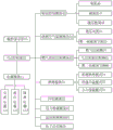
fig. 4 is a connection flow block diagram of the PLC controller of the present invention.
The labels in the figure are: 1-furnace body, 2-electric control cabinet, 3-connecting loop, 4-end cover lifting power unit, 41-driving component, 42-driving control module, 43-end cover, 44-crank rocker arm, 45-rotating shaft, 46-motor, 47-speed reducer, 48-hydraulic band brake, 5-combustion air supply and control unit, 51-combustion air structure, 52-combustion air monitoring module, 53-combustion air pipeline, 54-high pressure fan, 55-first electromagnetic regulating valve, 6-gas supply and control unit, 61-gas supply component, 62-gas supply control module, 63-gas pipeline, 64-gas filter, 65-pneumatic quick cut-off valve, 66-second electromagnetic regulating valve, 67-a blowoff valve, 7-a combustion condition control and real-time monitoring unit, 71-a combustion chamber, 72-a UV detector, 73-a baking module, 74-a conventional baking mode, 75-a rapid heating mode, 76-a small fire heat preservation mode, 8-a pressure detection unit, 81-a pressure detection sensor, 82-a pressure detection module, 9-a temperature detector, 91-a temperature detection module, 10-a PLC controller, 11-a power supply module, 111-an alternating current power supply, 112-a stabilized power supply, 113-an isolated power supply, 12-a manual switch gate valve, 13-a manual regulating valve, 14-an insulating protective layer, 15-an isolation display screen and 16-an electronic ignition touch gun.
Detailed Description
In order to make the objects, technical solutions and advantages of the present invention more apparent, the present invention is further described in detail with reference to the following embodiments.
As shown in connection with fig. 1-4;
an automatic control system of a baking furnace comprises a furnace body 1 and an electric control cabinet 2, a connecting loop 3 is further arranged between the furnace body 1 and the electric control cabinet 2, the connecting loop 3 comprises an end cover lifting power unit 4, combustion air is supplied to a control unit 5, fuel gas is supplied to the control unit 6, a combustion working condition control and real-time monitoring unit 7 and a pressure detection unit 8, the end cover lifting power unit 4 comprises a driving component 41 arranged on the furnace body 1 and a driving control module 42 used for controlling and driving the end cover 43 to lift, the driving component 41 comprises an end cover 43 arranged at the upper end of the furnace body 1, a crank rocker arm 44 used for fixedly connecting the end cover 43 to lift, a rotating shaft 45 vertically arranged and penetrating through the tail end of the crank rocker arm 44 and a motor 46 connected with the rotating shaft 45, the motor 46 is electrically connected with the driving control module 42, the output end of the motor 46 is further connected with a speed reducer 47, a hydraulic band-type brake 48 is further arranged between the speed reducer 47 and the rotating shaft 45, and the speed reducer 47 and the hydraulic band-type brake 48 are electrically connected with the PLC 10 respectively.
Setting an end cover lifting power unit: the steel ladle baking device is composed of a motor, a speed reducer, a hydraulic band-type brake and the like, the parts provide power for a baking system, a power device such as the motor is fixedly installed on a base, a first gear is arranged on a rotating shaft, a second gear is arranged in one end of a crank rocker, the first gear is in meshing transmission with the second gear to drive the crank rocker to rotate, so that an end cover can be freely opened, the maximum inclination angle can reach 85 degrees, the steel ladle lifting is facilitated, the structure is safe and reliable, the operation is stable, the space is greatly saved, the faults are reduced, the maintenance is convenient, the parts are all arranged in an area far away from a fire source, the steel ladle baking device is durable, and a limiting block of a mechanical structure and an electrical structure is installed near the rotating shaft, so that the operation safety of the device is ensured.
The combustion air supply and control unit 5 comprises a combustion air structure 51 connected and installed in the furnace body 1 and a combustion air monitoring module 52 for monitoring combustion air supply, flow regulation and data signal feedback and control, wherein the combustion air structure 51 comprises a combustion air pipeline 53 leading into the furnace body 1, a high-pressure fan 54 arranged on the combustion air pipeline 53 and a first electromagnetic regulating valve 55 installed on the combustion air pipeline 53, the high-pressure fan 54 and the first electromagnetic regulating valve 55 are respectively and electrically connected with the combustion air monitoring module 52, the combustion air supply and control unit is arranged and comprises a high-pressure fan, an electromagnetic regulating valve, a manual regulating valve and the like, the temperature rise and baking of ladle preheating are met according to the characteristics of the fan and the automatic regulation of valves, and the intelligent control of the structure is realized through intelligent automatic control and standby manual operation control, through setting up gas filter, manual switch gate valve, pressure detection sensor, pneumatic quick cut-off valve, electromagnetic control valve, blowoff valve isotructure, the quick cut-off valve is supplied with at the electric wire netting and is fallen off, the gas pressure is low or the fluctuation range is big when the unexpected circumstances such as the automatic cutout gas, and gas filter can filter moisture and impurity in the gas to guarantee the gas and last stable burning.
The gas supply and control unit 6 comprises a gas supply assembly 61 leading into the furnace body 1 and a gas supply control module 62 for monitoring gas supply, flow regulation and data signal feedback and control, wherein the gas supply assembly 61 comprises a gas pipeline 63 arranged in the furnace body 1, a gas filter 64 arranged on the gas pipeline 63, a pneumatic quick cut-off valve 65 arranged on the gas pipeline 63 and positioned on the left side of the gas filter 64, a second electromagnetic regulating valve 66 arranged on the left side of the pneumatic quick cut-off valve 65 and a blow-off valve 67 arranged on the gas pipeline 63, the gas supply control module 62 is respectively electrically connected with the gas filter 64, the pneumatic quick cut-off valve 65 and the second electromagnetic regulating valve 66, and a manual switch gate valve 12 and a manual regulating valve 13 for standby are arranged on the combustion air pipeline 53 and the gas pipeline 63.
Through setting up burning operating mode control and real-time supervision unit, carry out real-time supervision to the burning operating mode, when UV detector can not monitor flame, the transmission signal gives pneumatic quick cut-off valve, equipment automatic cutout gas is supplied with, carry out nitrogen gas and sweep, and send out the audible and visual warning, through setting up the pressure detection sensor who detects gas pipeline pressure and be used for detecting combustion air pipeline pressure, the pressure numerical value of pressure detection sensor can the real-time pressure of gas and combustion air of audio-visual display on the touch-control display screen, send audible and visual warning when pressure is crossed low or undulant too greatly, and cut off corresponding control flap, set up by temperature thermocouple, the structure of constituteing such as compensation wire, realize the temperature of overall process developments roaster, and carry out audio-visual demonstration, and the conveyor capacity of real-time adjustment gas and air according to the temperature in the roaster.
The combustion condition control and real-time monitoring unit 7 comprises a combustion chamber 71 arranged in the furnace body 1, a UV detector 72 arranged in the combustion chamber 71 and used for monitoring combustion flame, and a baking module 73 used for detecting the combustion condition in the combustion chamber 71 and controlling different combustion modes, wherein the UV detector 72 is connected with a pneumatic quick cut-off valve 65, an electronic ignition gun 16 is also arranged in the combustion chamber 71 of the furnace body 1 through a bracket, the electronic ignition gun 16 is electrically connected with the PLC 10, the electronic ignition gun is arranged in the furnace body and can automatically ignite big fire, the baking module 73 comprises a conventional baking mode 74, a rapid heating mode 75 and a small fire heat preservation mode 76, the baking module 73 is electrically connected to the first electromagnetic adjusting valve 55 and the second electromagnetic adjusting valve 66, respectively.
According to the electricity consumption of the electric instrument, the 380V alternating current power supply, the power supply capacity is reasonably selected, an isolation power supply and a voltage-stabilized power supply are arranged, the normal operation of the electric instrument, the instrument and the machinery is ensured, and short circuit and overload protection are carried out on a loop; the PLC integrated structure is set through signal acquisition and feedback of a primary instrument on site, and the drive control module is used for controlling and driving the end cover to lift; the combustion air monitoring module is used for monitoring the supply of combustion air, flow regulation and data signal feedback and control; the gas supply control module is used for monitoring gas supply, flow regulation and data signal feedback and control; the module of toasting for detect the combustion situation in the combustion chamber and control different combustion modes, the system is inside to set up different toasting curves respectively as required, every curve corresponds different heating demands respectively, if conventional toast, rapid heating up, the soft fire keeps warm etc. as long as select the heating mode that corresponds then the start program during operation start button can, the system can adjust flame to the soft fire heat preservation state automatically when toasting the program operation end, end the button until the start program, in order to realize effectively reducing intensity of labour and reduce the waste of unordered toasting gas.
The pressure detection unit 8 comprises a pressure detection sensor 81 for detecting the pressure of the gas pipeline 63 and the pressure of the combustion air pipeline 53 and a pressure detection module 82 for monitoring the gas supply pressure, the combustion air supply pressure and the feedback and control of data signals, the pressure detection sensor 81 is electrically connected with the pressure detection module 82, a temperature detection module 91 is further arranged in the furnace body 1, the temperature detector 9 is electrically connected with the temperature detector 9, real-time signals are fed back, and the temperature detector 9 is electrically connected with the temperature detection module 91; the temperature detector 9 comprises a temperature thermocouple and a compensating wire connected with the temperature thermocouple, the combustion condition control and real-time monitoring unit 7 and the pressure detection unit 8 are both provided with audible and visual alarms, and the audible and visual alarms are electrically connected with the PLC 10.
Be provided with PLC controller 10 in automatically controlled cabinet 2, and drive control module 42, combustion air monitoring module 52, control module 62 is supplied with in the gas, toast module 73, pressure detection module 82 and temperature detection module 91 are all integrated to be set up in PLC controller 10, still be provided with the power module 11 of connecting PLC controller 10 in automatically controlled cabinet 2, automatically controlled cabinet 2 adopts explosion-proof automatically controlled cabinet 2, and the surface of automatically controlled cabinet 2 is provided with insulating protective layer 14, still be provided with the touch-control display screen 15 that links to each other with PLC controller 10 on the surface of automatically controlled cabinet 2, power module 11 in automatically controlled cabinet 2 includes 380V alternating current power supply 111, constant voltage power supply 112 that links to each other with alternating current power supply 111 and the isolated power supply 113 that links to each other with constant voltage power supply 112.
The electric control cabinet implements different controls on baking states and mechanical equipment to achieve the expected baking purpose, an operator can select an automatic control mode on a touch control display screen, can select and call different baking curves, can set, modify various process parameters and display in real time, can display and inquire historical curves such as baking temperature and the like, can flexibly input the baking temperature curve according to the baking requirement of refractory materials, can call different baking curves from a touch screen picture as required, a control system accurately controls the air-fuel ratio according to the real-time feedback of the baking temperature, adjusts the flow of gas and combustion-supporting air in real time, reduces the gas consumption and the emission of nitrogen oxides, realizes intelligent baking, and starts to operate automatically by one key when baking is carried out, and the system can automatically adjust the operating parameters according to the actual conditions, the automatic adjustment air-fuel ratio, whole process need not manual operation, has changed the situation that relies on eyes to observe and experience to judge to toast in the past, has effectively reduced the consumption of gas, has improved operational environment, combines intelligent air-fuel ratio control technique, accurate control gas consumption, the inhaled quantity and the participation of the combustion-supporting wind of accurate control, reduce gas consumption more than 30% from the source, reduce the flue gas emission temperature, reduce the emission of nitrogen oxide and waste gas, realize energy-concerving and environment-protective.
The above description is only for the purpose of illustrating the preferred embodiments of the present invention and is not to be construed as limiting the invention, and any modifications, equivalents and improvements made within the spirit and principle of the present invention are intended to be included within the scope of the present invention.
Claims (10)
1. The utility model provides a bake out furnace automatic control system which characterized in that: comprises a furnace body (1) and an electric control cabinet (2), a connecting loop (3) is also arranged between the furnace body (1) and the electric control cabinet (2), the connecting loop (3) comprises an end cover lifting power unit (4), a combustion air supply and control unit (5), a fuel gas supply and control unit (6), a combustion condition control and real-time monitoring unit (7) and a pressure detection unit (8), the end cover lifting power unit (4) comprises a driving component (41) arranged on the furnace body (1) and a driving control module (42) used for controlling and driving the end cover (43) to lift, the driving component (41) comprises an end cover (43) arranged at the upper end of the furnace body (1), a crank rocker (44) used for fixedly connecting the end cover (43) to lift, a rotating shaft (45) penetrating through the tail end of the crank rocker (44) and vertically arranged, and a motor (46) connected with the rotating shaft (45), the motor (46) is electrically connected with the drive control module (42);
the combustion air supply and control unit (5) comprises a combustion air structure (51) connected and installed in the furnace body (1) and a combustion air monitoring module (52) for monitoring combustion air supply, flow regulation and data signal feedback and control, wherein the combustion air structure (51) comprises a combustion air pipeline (53) leading into the furnace body (1), a high-pressure fan (54) arranged on the combustion air pipeline (53) and a first electromagnetic regulating valve (55) installed on the combustion air pipeline (53), and the high-pressure fan (54) and the first electromagnetic regulating valve (55) are respectively and electrically connected with the combustion air monitoring module (52);
the gas supply and control unit (6) comprises a gas supply assembly (61) leading to the furnace body (1) and a gas supply control module (62) for monitoring gas supply, flow regulation and data signal feedback and control, wherein the gas supply assembly (61) comprises a gas pipeline (63) arranged in the furnace body (1), a gas filter (64) arranged on the gas pipeline (63), a pneumatic quick cut-off valve (65) arranged on the gas pipeline (63) and positioned on the left side of the gas filter (64), a second electromagnetic regulating valve (66) arranged on the left side of the pneumatic quick cut-off valve (65) and a blow-off valve (67) arranged on the gas pipeline (63), and the gas supply control module (62) is respectively connected with the gas filter (64), the pneumatic quick cut-off valve (65), The second electromagnetic regulating valve (66) is electrically connected;
burning operating mode control and real-time supervision unit (7) are including setting up combustion chamber (71), setting in furnace body (1) are in combustion chamber (71) and be used for monitoring burning flame UV detector (72) and be used for detecting the burning condition in combustion chamber (71) and control different combustion modes toast module (73), just UV detector (72) with pneumatic quick cut-off valve (65) link to each other, pressure detection unit (8) are including being used for detecting gas pipeline (63) pressure and being used for detecting pressure detection sensor (81) of combustion air pipeline (53) pressure and being used for monitoring gas supply pressure, combustion-supporting air supply pressure and data signal feedback and control's pressure detection module (82), pressure detection sensor (81) with pressure detection module (82) electric connection still be provided with in furnace body (1) thermodetector (9) with thermodetector (9) electric connection The temperature detection module (91) is used for receiving and feeding back a real-time signal, and the temperature detector (9) is electrically connected with the temperature detection module (91);
the automatic control system is characterized in that a PLC (programmable logic controller) (10) is arranged in the electric control cabinet (2), the driving control module (42), the combustion air monitoring module (52), the gas supply control module (62), the baking module (73), the pressure detection module (82) and the temperature detection module (91) are all integrally arranged in the PLC (10), and a power supply module (11) connected with the PLC (10) is further arranged in the electric control cabinet (2).
2. The automatic control system of claim 1, wherein: the output of motor (46) still is connected with speed reducer (47) with still be provided with hydraulic band-type brake (48) between pivot (45), just speed reducer (47) with hydraulic band-type brake (48) respectively with PLC controller (10) electric connection.
3. The automatic control system of claim 1, wherein: the baking module (73) comprises a conventional baking mode (74), a rapid heating mode (75) and a small fire heat preservation mode (76), and the baking module (73) is electrically connected with the first electromagnetic regulating valve (55) and the second electromagnetic regulating valve (66) respectively.
4. The automatic control system of claim 3, wherein: and a standby manual switch gate valve (12) and a manual regulating valve (13) are arranged on the combustion air pipeline (53) and the gas pipeline (63).
5. The automatic control system of claim 1, wherein: the combustion condition control and real-time monitoring unit (7) and the pressure detection unit (8) are both provided with audible and visual alarms, and the audible and visual alarms are electrically connected with the PLC (10).
6. The automatic control system of claim 1, wherein: the electric control cabinet (2) adopts an explosion-proof electric control cabinet (2), and an insulating protective layer (14) is arranged on the outer surface of the electric control cabinet (2).
7. The automatic control system of claim 6, wherein: and a touch display screen (15) connected with the PLC (10) is also arranged on the surface of the electric control cabinet (2).
8. The automatic control system of claim 7, wherein: the power supply module (11) in the electric control cabinet (2) comprises a 380V alternating current power supply (111), a stabilized voltage power supply (112) connected with the alternating current power supply (111) and an isolation power supply (113) connected with the stabilized voltage power supply (112).
9. The automatic control system of claim 1, wherein: an electronic ignition gun (16) is further arranged in the combustion chamber (71) of the furnace body (1) through a support, and the electronic ignition gun (16) is electrically connected with the PLC (10).
10. The automatic control system of claim 1, wherein: the temperature detector (9) comprises a temperature thermocouple and a compensation lead connected with the temperature thermocouple.
Priority Applications (1)
| Application Number | Priority Date | Filing Date | Title |
|---|---|---|---|
| CN202110732884.XA CN113547110B (en) | 2021-06-29 | 2021-06-29 | Automatic control system of baking oven |
Applications Claiming Priority (1)
| Application Number | Priority Date | Filing Date | Title |
|---|---|---|---|
| CN202110732884.XA CN113547110B (en) | 2021-06-29 | 2021-06-29 | Automatic control system of baking oven |
Publications (2)
| Publication Number | Publication Date |
|---|---|
| CN113547110A true CN113547110A (en) | 2021-10-26 |
| CN113547110B CN113547110B (en) | 2023-12-05 |
Family
ID=78131109
Family Applications (1)
| Application Number | Title | Priority Date | Filing Date |
|---|---|---|---|
| CN202110732884.XA Active CN113547110B (en) | 2021-06-29 | 2021-06-29 | Automatic control system of baking oven |
Country Status (1)
| Country | Link |
|---|---|
| CN (1) | CN113547110B (en) |
Cited By (1)
| Publication number | Priority date | Publication date | Assignee | Title |
|---|---|---|---|---|
| WO2023215928A1 (en) * | 2022-05-10 | 2023-11-16 | Fill Gesellschaft M.B.H. | Preheating station for preheating a melt transportation device |
Citations (9)
| Publication number | Priority date | Publication date | Assignee | Title |
|---|---|---|---|---|
| ES1056724U (en) * | 2004-01-30 | 2004-05-01 | Fagor, S. Coop. | Gas burner control for a bake oven |
| WO2010101171A1 (en) * | 2009-03-03 | 2010-09-10 | Miyatani Kazuo | Furnace for woody bulk fuel and method for controlling combustion of the same, hot air generating device using the furnace and method for utilizing smoke exhaust from furnace for woody bulk fuel |
| US20110269085A1 (en) * | 2004-03-23 | 2011-11-03 | Wiker John H | Conveyor oven apparatus and method |
| CN102444910A (en) * | 2011-12-31 | 2012-05-09 | 杭州杭真真空工程技术有限公司 | Combustion control system |
| CN202393191U (en) * | 2011-12-15 | 2012-08-22 | 陕西方园冶金设备有限公司 | Alloy baking device |
| JP2018030137A (en) * | 2016-08-22 | 2018-03-01 | 特殊電極株式会社 | Pan preheater and pan preheating method |
| CN107913998A (en) * | 2016-08-31 | 2018-04-17 | 浙江华顺炉业有限公司 | A kind of ladle baking facilities and its control system |
| CN111468709A (en) * | 2020-05-11 | 2020-07-31 | 北京君合悦科技发展有限公司 | Automatic baking system and method of ladle roaster |
| CN111561699A (en) * | 2020-06-17 | 2020-08-21 | 上海震泓环保科技有限公司 | High-efficient accurate intelligent refractory material baking system |
-
2021
- 2021-06-29 CN CN202110732884.XA patent/CN113547110B/en active Active
Patent Citations (9)
| Publication number | Priority date | Publication date | Assignee | Title |
|---|---|---|---|---|
| ES1056724U (en) * | 2004-01-30 | 2004-05-01 | Fagor, S. Coop. | Gas burner control for a bake oven |
| US20110269085A1 (en) * | 2004-03-23 | 2011-11-03 | Wiker John H | Conveyor oven apparatus and method |
| WO2010101171A1 (en) * | 2009-03-03 | 2010-09-10 | Miyatani Kazuo | Furnace for woody bulk fuel and method for controlling combustion of the same, hot air generating device using the furnace and method for utilizing smoke exhaust from furnace for woody bulk fuel |
| CN202393191U (en) * | 2011-12-15 | 2012-08-22 | 陕西方园冶金设备有限公司 | Alloy baking device |
| CN102444910A (en) * | 2011-12-31 | 2012-05-09 | 杭州杭真真空工程技术有限公司 | Combustion control system |
| JP2018030137A (en) * | 2016-08-22 | 2018-03-01 | 特殊電極株式会社 | Pan preheater and pan preheating method |
| CN107913998A (en) * | 2016-08-31 | 2018-04-17 | 浙江华顺炉业有限公司 | A kind of ladle baking facilities and its control system |
| CN111468709A (en) * | 2020-05-11 | 2020-07-31 | 北京君合悦科技发展有限公司 | Automatic baking system and method of ladle roaster |
| CN111561699A (en) * | 2020-06-17 | 2020-08-21 | 上海震泓环保科技有限公司 | High-efficient accurate intelligent refractory material baking system |
Non-Patent Citations (1)
| Title |
|---|
| 张吉美;叶婷;王辉;: "蓄热式钢包烘烤装置自动控制系统的应用", 冶金自动化, no. 01 * |
Cited By (1)
| Publication number | Priority date | Publication date | Assignee | Title |
|---|---|---|---|---|
| WO2023215928A1 (en) * | 2022-05-10 | 2023-11-16 | Fill Gesellschaft M.B.H. | Preheating station for preheating a melt transportation device |
Also Published As
| Publication number | Publication date |
|---|---|
| CN113547110B (en) | 2023-12-05 |
Similar Documents
| Publication | Publication Date | Title |
|---|---|---|
| CN102721288B (en) | High-efficiency intelligentized heating furnace control method | |
| CN113547110A (en) | Automatic control system of baking oven | |
| CN204630407U (en) | Temperature control equipment and reheat furnace system | |
| CN202024361U (en) | Ignition controller capable of monitoring automatically | |
| CN107062314A (en) | A kind of novel intelligent gas range device | |
| CN105522145B (en) | A kind of molten aluminum bull ladle temperature control heating system | |
| CN110500878A (en) | Vacuum anaerobic curing oven | |
| CN203343425U (en) | Fast baking device for ladle | |
| CN207815375U (en) | A kind of secondary air register control system | |
| CN203454218U (en) | Intelligent gas stove | |
| CN113267041B (en) | Full-automatic control system and control method for continuous production kiln | |
| CN210718597U (en) | Vacuum oxygen-free curing oven | |
| CN205980355U (en) | Automated control system of hot water machine | |
| CN214017163U (en) | Baking oven with electric heating and natural gas heating functions | |
| CN210802089U (en) | Double-gas burner controller | |
| CN107971045A (en) | A kind of general-purpose vertical activates furnace system | |
| CN209310048U (en) | A kind of ignition control device of cooking stove | |
| CN109028055B (en) | A kind of accurate temperature control and safe intelligent controller | |
| CN203431941U (en) | Air supply control device of gas stove | |
| CN219398834U (en) | Oxidation furnace fire extinguishing system | |
| CN110594749A (en) | Hazardous waste plasma gasification process control system | |
| CN207230609U (en) | A kind of Industrial Boiler Automatic Optimal control system | |
| CN213714000U (en) | Intelligent burner control device | |
| CN211717140U (en) | Oxygen supply combustion device for kiln | |
| CN216716287U (en) | Safety protection device for combustion furnace of unfreezing warehouse |
Legal Events
| Date | Code | Title | Description |
|---|---|---|---|
| PB01 | Publication | ||
| PB01 | Publication | ||
| SE01 | Entry into force of request for substantive examination | ||
| SE01 | Entry into force of request for substantive examination | ||
| GR01 | Patent grant | ||
| GR01 | Patent grant |