CN113445708A - Windproof intelligent wall surface spraying robot for high-rise building - Google Patents
Windproof intelligent wall surface spraying robot for high-rise building Download PDFInfo
- Publication number
- CN113445708A CN113445708A CN202110917745.4A CN202110917745A CN113445708A CN 113445708 A CN113445708 A CN 113445708A CN 202110917745 A CN202110917745 A CN 202110917745A CN 113445708 A CN113445708 A CN 113445708A
- Authority
- CN
- China
- Prior art keywords
- machine body
- wall surface
- screw rod
- arm
- spraying
- Prior art date
- Legal status (The legal status is an assumption and is not a legal conclusion. Google has not performed a legal analysis and makes no representation as to the accuracy of the status listed.)
- Pending
Links
Images


Classifications
-
- E—FIXED CONSTRUCTIONS
- E04—BUILDING
- E04F—FINISHING WORK ON BUILDINGS, e.g. STAIRS, FLOORS
- E04F21/00—Implements for finishing work on buildings
- E04F21/02—Implements for finishing work on buildings for applying plasticised masses to surfaces, e.g. plastering walls
- E04F21/06—Implements for applying plaster, insulating material, or the like
- E04F21/08—Mechanical implements
Abstract
The invention discloses a windproof intelligent wall surface spraying robot for a high-rise building, which consists of an upper machine body and a lower machine body, wherein the upper machine body works on the roof, and the upper machine body is connected with the lower machine body through a rope and controls the lower machine body to move vertically and transversely; the lower machine body is fixed on the wall surface through the adsorption feet, and the middle foot and the edge foot of each adsorption foot alternately move to ensure that the robot can normally work under the condition of strong wind; the spray gun loaded on the lower machine body has multiple degrees of freedom, and the flexibility is greatly improved. The invention has the advantages of strong wind resistance, high spraying action flexibility, high safety coefficient and the like, and greatly improves the safety performance, the spraying quality and the working efficiency compared with like products.
Description
Technical Field
The invention relates to a spraying device, in particular to a windproof intelligent wall surface spraying robot for a high-rise building.
Background
The falling of the ceramic tiles on the outer wall of the building seriously threatens the life safety of personnel, and has related regulations: the use of stone materials such as ceramic tiles and the like in buildings with the height of more than 100 meters is forbidden, and the use of the original stone paint in balancing beauty and safety is realized in more and more high-rise buildings, particularly high-rise residences. The traditional manual operation mode of manual spraying through a hanging basket by workers seriously has the problems of low working efficiency, large potential safety hazard, harm to the health of the workers, uneven coating and the like.
Chinese patent CN 211114662U, publication No. 2020.07.28, discloses a building outer wall decoration intelligent multifunctional spraying machine, which comprises a hanging basket and a lifting device, and realizes the intelligent spraying and obstacle avoidance functions of the outer wall. In practical application, the device does not have the dependent relation with the outer wall, exists the easy problem of rocking of during operation hanging flower basket, and is difficult to realize moving about of hanging flower basket, and the construction procedure is loaded down with trivial details.
Chinese patent CN 111364736 a, publication No. 2020.07.03, discloses a building outer wall spraying device with positioning function, which comprises a spraying robot, a multi-channel spraying component, a storage bin, a pump, a controller, and the like; the functions of climbing, automatic spraying and the like can be realized; however, in practical application, the reliability problem exists in the mode that the sponge sucker is fixed with the wall body, and the climbing device does not have the windproof function, so that potential safety hazards exist in the operation process when wind is encountered.
Chinese patent CN 210478871U, published 2020.05.08, discloses a wall-climbing cleaning robot, which comprises a lower beam skeleton, a single chip microcomputer, a sucker mechanism and other devices; in practical application, the robot is fixed only by the aid of the suckers, so that the robot is reliable and has no windproof capability.
Chinese patent CN 109736546A, published japanese 2019.05.10, which discloses a modular multifunctional robot for scraping dust, spraying and cleaning on the outer wall surface, comprising two parts, namely a base control robot and an operating robot. The telescopic hoisting support of the robot is controlled through the base, and the movement of the manufacturing robot is controlled under the control of the cable; the operation robot carries out construction operation in a required construction area according to detection of the sensor. In practical application, the working robot is not attached to the outer wall in the lifting process and the working process, has no windproof capability, is easy to shake and has potential safety hazards; the operation robot is not supported by the wall surface, and wind power or spraying backflushing can cause the operation robot to collide with the wall surface, so that danger is generated.
Disclosure of Invention
The invention provides the windproof intelligent wall surface spraying robot for the high-rise building, which has the advantages of high automatic control degree, strong wind resistance and high safety coefficient, and aims to overcome the defects in the prior art so as to practically improve the spraying quality and the working efficiency.
The invention adopts the following technical scheme for realizing the purpose of the invention:
the invention relates to a windproof intelligent wall surface spraying robot for a high-rise building, which is characterized in that:
the robot consists of an upper machine body and a lower machine body, wherein the upper machine body works on the roof of a building, and the lower machine body works on the wall surface in an adsorption manner;
the upper machine body moves on the roof by utilizing the left and right pairs of universal wheel sets arranged at the bottom of the bottom plate of the upper machine body, so that the lower machine body can move on the roof;
the upper machine body is provided with a hoisting mechanism, a hoisting motor drives a winding drum through a transmission structure, one end of a rope is wound on the winding drum, the other end of the rope is connected with a lifting bolt on the lower machine body through the direction change of a fixed pulley arranged on a mechanical arm of the upper machine body, and the lower machine body is lifted by the rope to move vertically; the upper mechanical arm is a cantilever mechanical arm formed by hinging a large arm and a small arm, a telescopic large arm hydraulic rod is supported at the front end of the large arm, and a telescopic small arm hydraulic rod is supported between the large arm and the small arm and is used for controlling the cantilever length of the mechanical arm;
the lower machine body is provided with a travelling mechanism and an adsorption mechanism by taking a shell as a carrier, and the travelling mechanism is provided with a spraying mechanism;
the walking mechanism consists of a peripheral structure and a screw rod module;
the peripheral structure is a rectangular frame, each frame of the rectangular frame is a guide structure consisting of a linear guide rail and an auxiliary beam, and a guide rail sliding block is matched on the linear guide rail; a pair of X-direction frames in the rectangular frame form an X-direction guide structure, a pair of Y-direction frames form a Y-direction guide structure, and two adjacent frames are fixedly connected by a connecting block;
the screw rod module is characterized in that a transverse screw rod and a vertical screw rod are installed on a limiting block with a cross clamping groove in a cross shape, an inner support and an outer support are respectively arranged on the inner side and the outer side of the limiting block to form an object carrying platform, the spraying mechanism is loaded on the object carrying platform, and two ends of the transverse screw rod and two ends of the vertical screw rod are fixed on guide rail sliding blocks in corresponding frames in a rectangular frame in a one-to-one correspondence mode; a motor and a speed reducer are arranged for controlling the movement of the carrying platform in the rectangular frame through a screw rod module;
the inner support and the connecting blocks are provided with adsorption feet for adsorbing a wall surface, namely a middle foot arranged on the inner support and edge feet arranged on each connecting block;
the spraying mechanism is characterized in that a fixing plate is provided with a suspended spraying mechanical arm formed by connecting a first section of arm and a second section of arm in series, and the first section of arm and the second section of arm are hinged to control the spraying angle of a spray gun; and a spraying platform bottom plate is fixedly installed on the carrying platform, and the fixed plate is connected with the spraying platform bottom plate through a support shaft.
The windproof intelligent wall surface spraying robot for the high-rise building is also characterized in that: in the hoisting mechanism on the upper machine body, the front end of the small arm is connected with a horizontal suspender in a T shape, two ends of the horizontal suspender are respectively provided with a fixed pulley, the winding drum and the ropes are divided into a left side and a right side, and the ropes on the left side and the right side respectively realize the symmetrical suspension of the lower machine body on two sides through the direction change of the fixed pulley at the corresponding end of the horizontal suspender.
The windproof intelligent wall surface spraying robot for the high-rise building is also characterized in that: a balance weight box which is in a U shape and surrounds the mechanical arm is arranged on the upper machine body, the balance weight box is fixedly arranged on a rotary hanger seat, and the rotary hanger seat is supported by an upper machine body bottom plate; the weight of the content in the counterweight box is utilized to keep the gravity balance of the upper machine body and the lower machine body.
The windproof intelligent wall surface spraying robot for the high-rise building is also characterized in that: in the left and right pairs of universal wheel sets at the bottom of the upper machine body, each pair of universal wheel sets consists of a front universal wheel and a rear universal wheel, and the two universal wheels in each pair of universal wheel sets are connected by a directional transmission shaft; a driving servo motor is arranged and used for driving the universal wheel to drive the upper machine body to move, and a rotating servo motor is arranged and used for driving the universal wheel to drive the upper machine body to adjust the direction.
The windproof intelligent wall surface spraying robot for the high-rise building is also characterized in that: the first section of arm and the second section of arm which form the spraying mechanical arm are both parallel-connected arms; the left side and the right side of a fixing plate of the spraying mechanism are respectively provided with a group of power devices consisting of a servo motor and a turbine disc, wherein the right power device controls the rotation of a right-side first-section arm, the left power device controls the rotation of a second-section arm through a first-section arm transmission rod, and a connecting piece and a second-section arm transmission rod are further arranged in the spraying mechanical arm to form a mechanical linkage structure.
The windproof intelligent wall surface spraying robot for the high-rise building is also characterized in that:
the control mode of each adsorption foot in the lower machine body is set as follows:
the first method is as follows: all edges are adsorbed by feet, the middle foot is loosened, so that the rectangular frame in the upper machine body is fixed with the wall surface, and the carrying platform is movable; the motor drives the screw rod module to realize that the carrying platform moves along the transverse screw rod or the vertical screw rod in the rectangular frame;
the second method comprises the following steps: all the adsorption feet are loosened, so that the whole lower machine body is separated from the wall surface, and the whole lower machine body is lifted by using a hoisting mechanism in the upper machine body, so that the whole lower machine body moves vertically;
the third method comprises the following steps: all the adsorption feet are loosened, so that the whole lower machine body is separated from the wall surface and is driven by the traveling mechanism in the upper machine body to realize the transverse movement of the lower machine body;
the method is as follows: the method comprises the following steps that firstly, each edge foot is adsorbed, the middle foot is loosened, a rectangular frame in a lower machine body is fixed with a wall surface, the middle foot is separated from the wall surface, a motor rotates forwards to drive a vertical screw rod in a screw rod module to rotate forwards, and a carrying platform moves upwards to the top end along the vertical screw rod; secondly, loosening the edges of the upper body and adsorbing the middle foot to separate the rectangular frame from the wall surface, fixing the object carrying platform with the wall surface through the middle foot, reversely rotating the vertical screw rod in the screw rod module by utilizing the motor to drive the rectangular frame to move upwards along the vertical screw rod until the object carrying platform returns to the bottom end of the vertical screw rod again, and realizing the upward movement of the whole upper body one step; the mode corresponding to the fourth mode can realize the movement of the whole upper body to the next step and the movement of one step to the left or the right.
Compared with the prior art, the invention has the beneficial effects that:
1. the invention has high automatic control degree, strong wind resistance and high safety factor, and can practically improve the spraying quality and the working efficiency; the edge foot and the middle foot in the lower machine body work cooperatively and are matched with the upper machine body to carry out balanced lifting on the lower machine body by using the rope, so that the wind resistance of the lower machine body is greatly enhanced, and the safety coefficient is improved;
2. the spray gun has flexible spraying angle, can deal with the difficult spraying problem of various irregular wall surfaces, and avoids dead angles;
3. the upper machine body can be directly transferred to another adjacent wall surface by utilizing the rotary hanger base at the bottom of the upper machine body in a flexible moving mode, so that the installation time of equipment is greatly shortened;
4. according to the invention, the mechanical arm is arranged in the upper machine body, and the distance between the lower machine body and the wall surface is controlled by adjusting the opening and closing angle of the mechanical arm, so that collision is effectively avoided, and the safety of the working process is improved;
5. according to the invention, various sensors and detectors are arranged, intelligent control can be realized through manual operation, the intelligent control device is used for replacing manual hanging basket operation, so that the safety and the working efficiency are greatly improved, and the intelligent control device can be widely applied to various works aiming at the wall surface, including wall body detection and spray-washing work.
Drawings
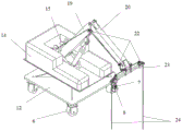
FIG. 1 is a schematic view of the overall structure of the robot according to the present invention;
FIG. 2 is a schematic view of a three-dimensional structure of an upper body of the robot according to the present invention;
FIG. 3 is a schematic front view of the upper body of the robot of the present invention;
FIG. 4 is a schematic view of the lower body structure of the robot of the present invention;
FIG. 5 is a schematic view of the structure of the traveling mechanism in the lower body of the robot according to the present invention;
FIG. 6 is a schematic diagram of a midfoot structure in a robot of the present invention;
FIG. 7 is a schematic diagram of a structure of a rim foot in the robot of the present invention;
FIG. 8 is a schematic perspective view of a spraying device in the robot according to the present invention;
FIG. 9 is a schematic front view of a spraying device in the robot of the present invention;
FIG. 10 is a schematic diagram of a walking track of the robot according to the present invention;
reference numbers in the figures: 1 upper machine body, 2 lower machine body, 3 wall surface, 4 building, 5 roof, 6 universal wheels, 7 driving servo motor, 8 power reducer, 9 steering body, 10 rotating servo motor, 11 direction transmission shaft, 12 upper machine body bottom plate, 13 rotating hanger seat, 14 balance weight box, 15 winding drum, 16 peripheral structure, 18 large arm hydraulic rod, 17 rope, 19 large arm, 20 small arm, 21 small arm hydraulic rod, 22 fixed pulley, 23 horizontal suspension rod, 24 suspension rope, 25 shell, 26 lead screw module, 27 optical axis, 28 lead screw, 29 motor, 30 reducer, 31 linear guide rail, 32 controller, 33 environmental camera, 34 objective platform, 35 middle foot push rod cylinder, 36 middle foot piston rod, 37 cross claw disc, 38 middle foot connecting piece, 39 middle foot sucker, 40 edge foot push rod cylinder, 41 edge foot piston rod, 42 edge foot connecting piece, 43 edge foot sucker, 43 edge sucker, and the like, The device comprises a base plate gyroscope 44, a base plate turbine disk 45, a right motor 46, a spraying platform base plate 47, a right turbine disk 48, a left turbine disk 49, a left motor 50, a one-section arm transmission rod 51, a connecting piece 52, a two-section arm transmission rod 53, a connecting shaft 54, a one-section arm 55, a two-section arm 56, a spray gun camera 57, a spray gun 58, a support shaft 59, a fixing plate 60, a laser range finder 61, an air velocity sensor 62, a lifting eye screw 63, an auxiliary beam 64, a guide rail slider 65, a connecting block 66, a limiting block 67, an outer support 68, an inner support 69 and a support 70.
Detailed Description
Referring to fig. 1, the windproof intelligent wall surface spraying robot for the high-rise building in the embodiment is composed of an upper machine body 1 and a lower machine body 2, wherein the upper machine body 1 works on a roof 5 of a building 4, and the lower machine body 2 adsorbs and works on a wall surface 3.
Fig. 2, 3 and 10 show that the upper machine body 1 moves on the roof 5 by using two pairs of right and left universal wheel sets arranged at the bottom of the bottom plate 12 of the upper machine body, so that the lower machine body 2 can move on the roof 5; the upper machine body 1 is provided with a hoisting mechanism, a hoisting motor drives a winding drum 15 through a transmission structure, the winding drum 15 is fixed on an upper machine body bottom plate 12, one end of a rope 17 is wound on the winding drum 15, the other end of the rope 17 is connected with a lifting bolt 63 on the lower machine body 2 through the steering of a fixed pulley 22 arranged on an upper machine body mechanical arm, and the lower machine body 2 is lifted by the rope 17 to move vertically; in order to adjust the distance between the lower machine body 2 and the wall surface 3, the upper machine body mechanical arm is a cantilever mechanical arm formed by hinging a large arm 19 and a small arm 20, a telescopic large arm hydraulic rod 18 is supported at the front end of the large arm, and a telescopic small arm hydraulic rod 21 is supported between the large arm and the small arm and used for controlling the cantilever length of the mechanical arm.
Fig. 4 and 5 show that the lower body 2 is provided with a traveling mechanism and an adsorption mechanism by using the shell 25 as a carrier, and the traveling mechanism is loaded with a spraying mechanism; the walking mechanism consists of a peripheral structure 16 and a screw rod module 26; the peripheral structure 16 is a rectangular frame, each frame of the rectangular frame is a guide structure formed by a linear guide rail 31 and an auxiliary beam 64, and a guide rail sliding block 65 is matched on the linear guide rail 31; a pair of X-direction frames in the rectangular frame form an X-direction guide structure, a pair of Y-direction frames form a Y-direction guide structure, and two adjacent frames are fixedly connected by a connecting block 66; the screw rod module 26 is characterized in that a transverse screw rod and a vertical screw rod are arranged on a limiting block 67 with a cross clamping groove in a cross shape, an inner support 69 and an outer support 68 are respectively arranged on the inner side and the outer side of the limiting block 67 to form an object carrying platform 34, a spraying mechanism is loaded on the object carrying platform 34, and two ends of the transverse screw rod and two ends of the vertical screw rod are fixed on guide rail sliding blocks 65 in corresponding frames in a rectangular frame in a one-to-one correspondence mode through supporting seats 70; a motor 29 and a reducer 30 are arranged for controlling the movement of the carrying platform 34 in the rectangular frame through the screw rod module 26, and in order to enhance the strength of the screw rod module 26, optical axes 27 which are symmetrical on two sides and used for supporting are arranged for a screw rod 28 in the screw rod module 26; suction feet for sucking the wall surface 3 are provided on the inner holder 69 and the connection blocks 66, respectively, a middle foot provided on the inner holder 69 shown in fig. 6 and a side foot provided on each connection block 66 shown in fig. 7.
Fig. 6 shows that the middle foot is composed of a middle foot push rod cylinder 35, a middle foot piston rod 36, a cross claw disc 37, a middle foot connecting piece 38 and a middle foot sucker 39, the four groups of adsorption feet are connected together by the cross claw disc 37, the middle foot push rod cylinder 35 controls the middle foot piston rod 36 to stretch, a vacuum pump is arranged to control the middle foot sucker 39 to generate negative pressure or release the negative pressure so as to control the middle foot sucker 39 to be attracted with or released from the wall surface 3, and a negative pressure sensor for detecting the adsorption pressure is arranged on the inner side of the adsorption foot.
Fig. 7 shows that the edge foot is composed of an edge foot push rod cylinder 40, an edge foot piston rod 41, an edge foot connecting piece 42 and an edge foot sucker 43, the edge foot push rod cylinder 40 controls the edge foot piston rod 41 to stretch, a vacuum pump is arranged to control the edge foot sucker 43 to generate negative pressure or release the negative pressure so as to control the edge foot sucker 43 to be attracted or loosened with the wall surface 3, and a negative pressure sensor for detecting the adsorption pressure is arranged on the inner side of the adsorption foot.
Fig. 8 and 9 show that the spraying mechanism is a spraying mechanical arm which is provided with an overhang and formed by connecting a first-joint arm 55 and a second-joint arm 56 in series on a fixing plate 60, and the first-joint arm 55 and the second-joint arm 56 are arranged to be hinged to control the spraying angle of a spray gun 58; the spraying platform base plate 47 is fixedly installed on the carrying platform 34, the fixing plate 60 is connected with the spraying platform base plate 47 through the supporting shaft 59, and the base plate turbine disc 45 driven by the motor is arranged and used for driving the fixing plate 60 to rotate so as to adjust the position of the spraying mechanism and enlarge the spraying area of the spray gun 58.
In specific implementation, the corresponding technical measures also include:
as shown in fig. 2 and 3, in the hoisting mechanism on the upper machine body, in order to ensure the horizontal balance of the lower machine body 2, a horizontal boom 23 is connected to the front end of the small arm 19 in a "T" shape, fixed pulleys 22 are respectively arranged at both ends of the horizontal boom 23, the drum 15 and the ropes 17 are divided into left and right sides, the ropes 17 on the left and right sides are respectively turned by the fixed pulleys 22 at the corresponding ends of the horizontal boom 23, and the lower machine body 2 is symmetrically suspended on both sides by using a hoisting rope 24; a balance weight box 14 which is in a U shape and surrounds the mechanical arm is arranged on the upper machine body 1, the balance weight box 14 is fixedly arranged on a rotary hanger seat 13, and the rotary hanger seat 13 is supported by an upper machine body bottom plate 12; the weight of the content in the counterweight box 14 is utilized to keep the gravity balance of the upper machine body 1 and the lower machine body 2; in two pairs of left and right universal wheel sets at the bottom of the upper machine body 1, each pair of universal wheel sets is composed of a front universal wheel 6 and a rear universal wheel 6, and the two universal wheels 6 in each pair of universal wheel sets are connected by a directional transmission shaft 11; the driving servo motor 7 with the power reducer 8 is arranged for driving the universal wheel 6 to drive the upper machine body to move, the rotating servo motor 10 and the steering body 9 driven by the driving servo motor 10 are arranged for driving the universal wheel 6 to rotate and drive the upper machine body to adjust the direction, so that the walking and steering of the upper machine body 1 are ensured, and the transverse movement control of the lower machine body 2 is realized.
As shown in fig. 8 and 9, the first arm 55 and the second arm 56 constituting the painting robot are both parallel arms; a group of power devices consisting of a servo motor and a turbine disc are respectively arranged on the left side and the right side of a fixing plate 60 of the spraying mechanism, wherein the right power device controls the rotation of a right one-section arm, the left power device controls the rotation of a two-section arm through a one-section arm transmission rod 51, a connecting piece 52 and a two-section arm transmission rod 53 are further arranged in the spraying mechanical arm to form a mechanical linkage structure, and the front end of the two-section arm transmission rod 53 is connected with a connecting shaft 54 arranged on a spray gun bottom plate in a T shape; when the right motor 46 drives the right turbine disc 48 to rotate clockwise, the angle of the spray gun 58 is controlled to be adjusted downwards; conversely, when the right turbine disk 48 rotates counterclockwise, the spray gun 58 is controlled to adjust the angle upwards; when the left motor 50 drives the left turbine disc 49 to rotate clockwise, the second-section arm is controlled to rotate clockwise; conversely, when the left turbine disk 49 rotates anticlockwise, the two-section arm 56 is controlled to rotate anticlockwise, so that the position and the angle of the spray gun 58 are indirectly adjusted.
Various sensors are arranged for signal detection and automatic control, including:
fig. 4 shows that a laser range finder 61, an air velocity sensor 62 and an environment camera 33 are provided on the lower body 2; FIG. 9 shows a spray gun camera 57 mounted on the spray gun base plate in a direction toward the spray gun; fig. 8 shows that the base plate gyroscope 44 is provided on the fixing plate 60 of the painting mechanism.
The distance between the lower machine body 2 and the wall surface 3 is monitored in real time by using a laser range finder 61, and the operation safety is ensured by adjusting through an upper machine body mechanical arm;
detecting the wind speed at the time of work by the wind speed sensor 62;
the environment camera 33 is used for facilitating the staff to observe the working environment of the robot;
monitoring the spraying quality of the spray gun in real time by using the spray gun camera 57, adjusting the supply density of the coating in time, and reworking the omitted part;
the bottom plate gyroscope 44 is utilized to monitor signals of the lower body such as the direction, the level, the position, the moving speed and the like so as to control the real-time stability of the lower body;
in specific implementation, the control mode for each adsorption foot in the lower machine body 2 is as follows:
the first method is as follows: all edges are adsorbed by feet, the middle foot is loosened, so that the rectangular frame in the upper machine body 1 is fixed with the wall surface 3, and the carrying platform 34 is movable; the motor drives the screw rod module 26 to realize the displacement of the carrying platform 34 in the rectangular frame along the transverse screw rod or the vertical screw rod.
The second method comprises the following steps: all the adsorption feet are loosened, so that the whole lower machine body 1 is separated from the wall surface 3, and the hoisting mechanism in the upper machine body 1 is used for integrally hoisting the lower machine body 2, so that the whole lower machine body 2 can integrally and vertically move; this way is suitable for the wind speed is small, and the controller is used to adjust the rotating speed of the hoisting device, thereby controlling the lifting speed of the lower body 2.
The third method comprises the following steps: all the adsorption feet are loosened to separate the whole lower machine body 1 from the wall surface 3, and the lower machine body 2 is driven by the traveling mechanism in the upper machine body 1 to transversely move.
The method is as follows: in the first step, each edge foot is adsorbed and the middle foot is loosened, so that a rectangular frame in the lower machine body 2 is fixed with a wall surface 3, the middle foot is separated from the wall surface 3, and a motor rotates forwards to drive a vertical screw rod in a screw rod module 26 to rotate forwards, so that a carrying platform 34 moves upwards to the top end along the vertical screw rod; secondly, loosening the edges of the upper body and adsorbing the middle feet to separate the rectangular frame in the lower body 2 from the wall surface 3, fixing the object carrying platform 34 with the wall surface 3 through the middle feet, reversely rotating the vertical screw rod in the screw rod module 26 by utilizing a motor to drive the rectangular frame to move upwards along the vertical screw rod until the object carrying platform 34 returns to the bottom end of the vertical screw rod again, and realizing the integral upward one-step movement of the upper body; the mode corresponding to the fourth mode can realize the movement of the whole upper body to the next step and the movement of one step to the left or the right. When the wind speed exceeds the set working range, the movement of the upper machine body is controlled in a fourth mode to have good wind resistance.
As shown in fig. 10, after the lower body 2 finishes the spraying of one vertical surface, all the adsorption feet in the lower body 2 are released, the lower body 2 can be conveniently moved to the next vertical surface through the movement of the two pairs of universal wheels 6 in the upper body 1, and in the process, the opening and closing angle of the mechanical arm of the upper body 1 is adaptively adjusted, so that the lower body 2 is prevented from colliding with the wall surface 3.
When the border foot is in the adsorption state alright begin the spraying operation, can enlarge the spraying area through the removal of cargo platform 34, can eliminate the spraying dead angle through the regulation of spraying arm, through the rotation of bottom plate turbine disk 45, can realize two vertical planes of spraying simultaneously.
The controller 32 is used for controlling to enable the lower machine body 2 to carry out longitudinal repeated spraying operation on the wall surface 3, and the spray gun carries out repeated spraying operation in a mode of going from left to right and going from top to bottom; when the wall surface of a windowsill, a building ornament and the like protrudes, the opening and closing angle is adjusted by the mechanical arm in the upper machine body so as to adapt to the distance between the lower machine body and the protrusion and prevent collision; after the whole wall surface 3 is coated, the lower machine body 2 is rotated and moved to the next wall surface through the rotating hanger seat 13 in the upper machine body to continue the coating work.
Claims (6)
1. The utility model provides a type intelligence wall spraying robot is prevent wind to high-rise building, characterized by:
the robot consists of an upper machine body (1) and a lower machine body (2), wherein the upper machine body (1) works on a roof (5) of a building (4), and the lower machine body (2) works on a wall surface (3) in an adsorption manner;
the upper machine body (1) moves on the roof (5) by utilizing a left universal wheel set and a right universal wheel set which are arranged at the bottom of a bottom plate (12) of the upper machine body, so that the lower machine body (2) can move on the roof (5);
the upper machine body (1) is provided with a hoisting mechanism, a hoisting motor drives a winding drum (15) through a transmission structure, one end of a rope (17) is wound on the winding drum (15), the other end of the rope (17) is connected with a lifting bolt (63) on the lower machine body (2) through the steering of a fixed pulley (22) arranged on a mechanical arm of the upper machine body, and the rope (17) is used for lifting the vertical movement of the lower machine body (2); the upper mechanical arm is a cantilever mechanical arm formed by hinging a large arm (19) and a small arm (20), a telescopic large arm hydraulic rod (18) is supported at the front end of the large arm, and a telescopic small arm hydraulic rod (21) is supported between the large arm and the small arm and is used for controlling the cantilever length of the mechanical arm;
the lower machine body (2) is provided with a traveling mechanism and an adsorption mechanism by taking the shell (25) as a carrier, and the traveling mechanism is loaded with a spraying mechanism;
the running mechanism consists of a peripheral structure (16) and a screw rod module (26);
the peripheral structure (16) is a rectangular frame, each frame of the rectangular frame is a guide structure consisting of a linear guide rail (31) and an auxiliary beam (64), and a guide rail sliding block (65) is matched on the linear guide rail (31); a pair of X-direction frames in the rectangular frame form an X-direction guide structure, a pair of Y-direction frames form a Y-direction guide structure, and two adjacent frames are fixedly connected by a connecting block (66);
the screw rod module (26) is characterized in that a transverse screw rod and a vertical screw rod are installed on a limiting block (67) with a cross clamping groove in a cross shape, an inner support (69) and an outer support (68) are respectively arranged on the inner side and the outer side of the limiting block (67) to form an object carrying platform (34), the spraying mechanism is loaded on the object carrying platform (34), and two ends of the transverse screw rod and two ends of the vertical screw rod are fixed on guide rail sliding blocks (65) in corresponding frames in a rectangular frame in a one-to-one correspondence manner; a motor and a speed reducer are arranged for controlling the movement of the carrying platform (34) in the rectangular frame through a screw rod module (26);
adsorption feet for adsorbing the wall surface (3) are arranged on the inner support (69) and the connecting blocks (66), namely a middle foot arranged on the inner support (69) and edge feet arranged on the connecting blocks (66);
the spraying mechanism is a suspended spraying mechanical arm formed by connecting a first-section arm (55) and a second-section arm (56) in series on a fixing plate (60), and the first-section arm (55) and the second-section arm (56) are hinged to control the spraying angle of a spray gun (58); and a spraying platform bottom plate (47) is fixedly arranged on the loading platform (34), and the fixed plate (60) is connected with the spraying platform bottom plate (47) through a support shaft (59).
2. The high-rise building windproof intelligent wall surface spraying robot according to claim 1, characterized in that: in the hoisting mechanism on the upper machine body, the front end of a small arm (19) is connected with a horizontal suspender (23) in a T shape, two ends of the horizontal suspender (23) are respectively provided with a fixed pulley (22), the winding drum (15) and the ropes (17) are divided into a left side and a right side, and the ropes (17) on the left side and the right side are respectively turned by the fixed pulleys (22) at the corresponding ends of the horizontal suspender (23) to realize symmetrical suspension of the lower machine body (2) on two sides.
3. The high-rise building windproof intelligent wall surface spraying robot according to claim 1, characterized in that: a balance weight box (14) which is in a U shape and surrounds the mechanical arm is arranged on the upper machine body (1), the balance weight box (14) is fixedly arranged on a rotary hanger seat (13), and the rotary hanger seat (13) is supported by an upper machine body bottom plate (12); the weight of the content in the counterweight box (14) is utilized to keep the gravity balance of the upper machine body (1) and the lower machine body (2).
4. The high-rise building windproof intelligent wall surface spraying robot according to claim 1, characterized in that: in the left and right pairs of universal wheel sets at the bottom of the upper machine body (1), each pair of universal wheel sets is composed of a front universal wheel (6) and a rear universal wheel (6), and the two universal wheels (6) in each pair of universal wheel sets are connected by a directional transmission shaft (11); a driving servo motor (7) is arranged and used for driving the universal wheel (6) to drive the upper machine body to move, and a rotating servo motor (10) is arranged and used for driving the universal wheel (6) to drive the upper machine body to adjust the direction.
5. The high-rise building windproof intelligent wall surface spraying robot according to claim 1, characterized in that: the first section of arm (55) and the second section of arm (56) which form the spraying mechanical arm are both parallel-connected double arms; the left side and the right side of a fixing plate (60) of the spraying mechanism are respectively provided with a group of power devices consisting of a servo motor and a turbine disc, wherein the right power device controls the rotation of a right one-section arm, the left power device controls the rotation of a two-section arm (56) through a one-section arm transmission rod (51), and a connecting piece (52) and a two-section arm transmission rod (53) are further arranged in the spraying mechanical arm to form a mechanical linkage structure.
6. The high-rise building windproof intelligent wall surface spraying robot according to claim 1, characterized in that:
the control mode of each adsorption foot in the lower machine body (2) is set as follows:
the first method is as follows: all edges are adsorbed by feet, the middle foot is loosened, so that the rectangular frame in the upper machine body (1) is fixed with the wall surface (3), and the carrying platform (34) is movable; the motor drives the screw rod module (26) to realize the displacement of the carrying platform (34) in the rectangular frame along the transverse screw rod or the vertical screw rod;
the second method comprises the following steps: all the adsorption feet are loosened, so that the whole lower machine body (1) is separated from the wall surface (3), and the hoisting mechanism in the upper machine body (1) is used for integrally hoisting the lower machine body (2) to realize the vertical movement of the whole lower machine body (2);
the third method comprises the following steps: all the adsorption feet are loosened, so that the whole lower machine body (1) is separated from the wall surface (3), and the lower machine body (2) is driven by a traveling mechanism in the upper machine body (1) to transversely move;
the method is as follows: firstly, adsorbing each edge foot and loosening the middle foot to fix a rectangular frame in the lower machine body (2) with a wall surface (3) and separate the middle foot from the wall surface (3), and driving a vertical screw rod in a screw rod module (26) to rotate in the forward direction by utilizing the forward rotation of a motor to move a carrying platform (34) up to the top end along the vertical screw rod; secondly, loosening each edge foot and adsorbing each middle foot to separate a rectangular frame in the lower machine body (2) from the wall surface (3), fixing the object carrying platform (34) with the wall surface (3) through the middle foot, and reversely rotating a vertical screw rod in a screw rod module (26) by utilizing a motor to drive the rectangular frame to move upwards along the vertical screw rod until the object carrying platform (34) returns to the bottom end of the vertical screw rod again, so that the whole upper machine body moves upwards one step; the mode corresponding to the fourth mode can realize the movement of the whole upper body to the next step and the movement of one step to the left or the right.
Priority Applications (1)
| Application Number | Priority Date | Filing Date | Title |
|---|---|---|---|
| CN202110917745.4A CN113445708A (en) | 2021-08-11 | 2021-08-11 | Windproof intelligent wall surface spraying robot for high-rise building |
Applications Claiming Priority (1)
| Application Number | Priority Date | Filing Date | Title |
|---|---|---|---|
| CN202110917745.4A CN113445708A (en) | 2021-08-11 | 2021-08-11 | Windproof intelligent wall surface spraying robot for high-rise building |
Publications (1)
| Publication Number | Publication Date |
|---|---|
| CN113445708A true CN113445708A (en) | 2021-09-28 |
Family
ID=77818434
Family Applications (1)
| Application Number | Title | Priority Date | Filing Date |
|---|---|---|---|
| CN202110917745.4A Pending CN113445708A (en) | 2021-08-11 | 2021-08-11 | Windproof intelligent wall surface spraying robot for high-rise building |
Country Status (1)
| Country | Link |
|---|---|
| CN (1) | CN113445708A (en) |
Citations (10)
| Publication number | Priority date | Publication date | Assignee | Title |
|---|---|---|---|---|
| JP2001149273A (en) * | 1999-11-26 | 2001-06-05 | Maeda Corp | Device for cleaning external wall of construction |
| CN105178580A (en) * | 2015-09-22 | 2015-12-23 | 黄灿灿 | Mechanical arm type full-automatic painting machine |
| CN105643587A (en) * | 2016-03-04 | 2016-06-08 | 哈尔滨工业大学 | Thirteen-freedom spraying robot for outer surface of large ship body |
| CN107536566A (en) * | 2017-09-04 | 2018-01-05 | 常州工学院 | Based on monolithic processor controlled curtain cleaning robot control system and control method |
| CN108729683A (en) * | 2018-05-31 | 2018-11-02 | 陕西科技大学 | A kind of spider-shaped cleaning glass machine people |
| CN109124455A (en) * | 2018-10-30 | 2019-01-04 | 吉林大学 | Glass-cleaning robot and its control method outside building with self-identifying and obstacle avoidance ability |
| CN209579528U (en) * | 2018-12-13 | 2019-11-05 | 中铁建工集团有限公司 | A kind of cladding glass installation mechanical car |
| CN111287417A (en) * | 2020-04-07 | 2020-06-16 | 合肥工业大学 | Intelligent spraying robot for outer wall of high-rise building and control method thereof |
| CN111820828A (en) * | 2020-07-15 | 2020-10-27 | 袁海波 | Building curtain wall self-cleaning robot |
| CN112120615A (en) * | 2020-08-11 | 2020-12-25 | 杭州龙皓工程咨询有限公司 | Glass curtain wall cleaning equipment |
-
2021
- 2021-08-11 CN CN202110917745.4A patent/CN113445708A/en active Pending
Patent Citations (10)
| Publication number | Priority date | Publication date | Assignee | Title |
|---|---|---|---|---|
| JP2001149273A (en) * | 1999-11-26 | 2001-06-05 | Maeda Corp | Device for cleaning external wall of construction |
| CN105178580A (en) * | 2015-09-22 | 2015-12-23 | 黄灿灿 | Mechanical arm type full-automatic painting machine |
| CN105643587A (en) * | 2016-03-04 | 2016-06-08 | 哈尔滨工业大学 | Thirteen-freedom spraying robot for outer surface of large ship body |
| CN107536566A (en) * | 2017-09-04 | 2018-01-05 | 常州工学院 | Based on monolithic processor controlled curtain cleaning robot control system and control method |
| CN108729683A (en) * | 2018-05-31 | 2018-11-02 | 陕西科技大学 | A kind of spider-shaped cleaning glass machine people |
| CN109124455A (en) * | 2018-10-30 | 2019-01-04 | 吉林大学 | Glass-cleaning robot and its control method outside building with self-identifying and obstacle avoidance ability |
| CN209579528U (en) * | 2018-12-13 | 2019-11-05 | 中铁建工集团有限公司 | A kind of cladding glass installation mechanical car |
| CN111287417A (en) * | 2020-04-07 | 2020-06-16 | 合肥工业大学 | Intelligent spraying robot for outer wall of high-rise building and control method thereof |
| CN111820828A (en) * | 2020-07-15 | 2020-10-27 | 袁海波 | Building curtain wall self-cleaning robot |
| CN112120615A (en) * | 2020-08-11 | 2020-12-25 | 杭州龙皓工程咨询有限公司 | Glass curtain wall cleaning equipment |
Non-Patent Citations (1)
| Title |
|---|
| 王巍等: "一种轻型玻璃幕墙清洗机器人模型的研究", 《液压与气动》 * |
Similar Documents
| Publication | Publication Date | Title |
|---|---|---|
| KR102341480B1 (en) | Systems and methods for spray painting exterior walls of buildings | |
| CN111287417A (en) | Intelligent spraying robot for outer wall of high-rise building and control method thereof | |
| KR102352730B1 (en) | Systems and methods for cleaning exterior walls of buildings | |
| CN107200077B (en) | Three-body wall-climbing robot and obstacle crossing method thereof | |
| CN202542734U (en) | Glass hoisting and installing device | |
| CN211817748U (en) | High-rise building outer wall intelligent spraying robot | |
| KR20120094480A (en) | Climbing robot for travelling over adhesive surfaces | |
| CN109881872A (en) | Spray gun assembly and spray robot | |
| CN109958263A (en) | Spray robot | |
| CN112282306A (en) | Automatic spraying equipment with six degrees of freedom for outer wall | |
| CN1951641A (en) | Dual-purpose robot for derusting and painting oil tank in cavity and storeroom | |
| CN204474187U (en) | A kind of wall type turning crane | |
| CN113006348B (en) | Automatic installation type intelligent robot for high-altitude curtain wall | |
| CN113601485B (en) | Intelligent spraying robot for outer wall of high-rise building | |
| CN208822653U (en) | A kind of glass curtain wall cleaning machine device people | |
| CN212836778U (en) | Manipulator is used in supplementary installation of high altitude curtain | |
| CN113775162A (en) | Outer facade construction robot | |
| JP2000169083A (en) | Wall face work robot | |
| CN107717977B (en) | Mobile architecture system of aerial working robot | |
| CN113445708A (en) | Windproof intelligent wall surface spraying robot for high-rise building | |
| CN214402607U (en) | Automatic crawling spraying machine | |
| KR20170043379A (en) | An Operation Tool for Outer Walls of a Building and Gondola Unit Comprising the Operation Tool | |
| CN206707220U (en) | A kind of suspension type external wall of high-rise building multiple degrees of freedom plastering machine | |
| CN111317394A (en) | Curtain wall glass cleaning method without hoisting | |
| CN112873180A (en) | High-altitude operation suspension device and robot |
Legal Events
| Date | Code | Title | Description |
|---|---|---|---|
| PB01 | Publication | ||
| PB01 | Publication | ||
| SE01 | Entry into force of request for substantive examination | ||
| SE01 | Entry into force of request for substantive examination | ||
| RJ01 | Rejection of invention patent application after publication |
Application publication date: 20210928 |
|
| RJ01 | Rejection of invention patent application after publication |