Disclosure of Invention
1. In order to solve the technical defects, the invention adopts the technical scheme that a two-degree-of-freedom pan-tilt for an embedded semi-submersible type mobile robot is provided, and the two-degree-of-freedom pan-tilt is characterized by comprising a pan-tilt shell, a pan-tilt base, a camera shell, a pitching assembly, a rotating assembly and a mobile robot body, wherein the camera shell is connected to the pan-tilt shell through a pitching hollow shaft, the inner circuit of the camera shell passes through the pitching hollow shaft, the pitching assembly drives the camera shell to rotate around the axis of the pitching hollow shaft, the pan-tilt shell is fixedly arranged on the pan-tilt base, the pan-tilt base is provided with the rotating hollow shaft, the rotating assembly drives the pan-tilt shell to rotate around the axis of the rotating hollow shaft, the circuit circuits of the pan-tilt shell and the pan-tilt shell are connected with a controller of the mobile robot body through the rotating hollow shaft, the circuit line of the camera shell of the pitching hollow shaft is connected with a controller of the mobile robot body through the rotating hollow shaft, the axis of the pitching hollow shaft is perpendicular to the axis of the rotating hollow shaft, and the rotating hollow shaft is arranged in the mobile robot body.
Preferably, the pitching assembly comprises a pitching hollow shaft steering engine, a pitching hollow shaft steering engine fixing plate and a first belt pulley group, the pitching hollow shaft steering engine is arranged on the pitching hollow shaft steering engine fixing plate, and the pitching hollow shaft steering engine is in transmission connection with the camera shell through the first belt pulley group.
Preferably, the rotating assembly comprises a rotating hollow shaft steering engine, a rotating hollow shaft steering engine fixing plate and a second belt wheel set, the rotating hollow shaft steering engine is arranged on the rotating hollow shaft steering engine fixing plate, and the rotating hollow shaft steering engine is in transmission connection with the rotating hollow shaft through the second belt wheel set.
Preferably, the pitching hollow shaft steering engine fixing plate is installed on the holder shell, the rotating hollow shaft steering engine fixing plate is installed inside the mobile robot body, and the auxiliary light source and the camera are installed in the camera shell.
Preferably, the first belt pulley group is provided with two belt pulleys in transmission connection, one belt pulley is arranged on one side of the camera shell through a belt pulley mounting shaft, the belt pulley mounting shaft and the pitching hollow shaft are coaxially arranged, and the other belt pulley is arranged on an output shaft of the pitching hollow shaft steering engine.
Preferably, the second belt pulley set is provided with two belt pulleys in transmission connection, one belt pulley is arranged on the rotary hollow shaft, and the other belt pulley is arranged on an output shaft of the rotary hollow shaft steering engine.
Preferably, the pitching hollow shaft and the holder housing are connected through a flange bearing, and the belt wheel mounting shaft and the holder housing are connected through a flange bearing.
Preferably, a cradle head sealing cover is arranged corresponding to the rotating hollow shaft and is arranged on the mobile robot body, a sealing piece is arranged at the joint of the cradle head sealing cover and the mobile robot body, a rolling bearing is arranged in the cradle head sealing cover, sealing rings are arranged on two sides of the rolling bearing, and the rotating hollow shaft is connected with the cradle head sealing cover through the rolling bearing.
Preferably, an O-shaped sealing ring and a Glare ring are arranged inside the holder sealing cover, and the O-shaped sealing ring and the Glare ring are sleeved on the rotating hollow shaft.
Preferably, the rotating hollow shaft is a stepped shaft, and the cradle head shell structure is U-shaped.
Compared with the prior art, the invention has the beneficial effects that: the two-degree-of-freedom tripod head has the advantages of simple structure, large rotation angle, good sealing performance and difficult interference, the whole tripod head adopts an embedded and semi-submersible design, has good adaptability with a mobile robot, and high space utilization rate, the tripod head shell adopts a bottom opening mode, so that the tripod head can discharge water in time through gravity when raining and wading, the arrangement mode of the steering engine and the belt wheel effectively reduces the whole height of the tripod head, the steering engine is adopted for control, the cost is also reduced, and the two-degree-of-freedom tripod head is very suitable for the mobile robot to carry out image acquisition.
Detailed Description
The above and further features and advantages of the present invention are described in more detail below with reference to the accompanying drawings.
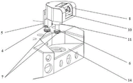
As shown in fig. 1, fig. 1 is a perspective view of the two-degree-of-freedom pan/tilt head; the two-degree-of-freedom cradle head adopts an embedded and semi-submersible design; the device comprises a tripod head shell 8, a tripod head base 9, a camera shell 10, a pitching component and a rotating component, wherein the camera shell 10 is connected to the tripod head shell 8 through a pitching hollow shaft 3, the pitching component drives the camera shell 10 to rotate around the axis of the pitching hollow shaft 3, the internal circuit of the camera shell 10 passes through the pitching hollow shaft 3, the tripod head shell 8 is fixedly arranged on the tripod head base 9, the tripod head base 9 is provided with a rotating hollow shaft 6, the rotating component drives the tripod head shell 8 to rotate around the axis of the rotating hollow shaft 6, the internal circuit of the camera shell 10 of the pitching hollow shaft 3 is also connected with an internal controller of the mobile robot through the rotating hollow shaft 6, the axes of the pitching hollow shaft 3 and the rotating hollow shaft 6 are vertically arranged, and the rotating hollow shaft is arranged inside the mobile robot body, so that the pan/tilt head is located inside the mobile robot body 14 with one degree of freedom.
The pitching assembly comprises a pitching hollow shaft steering engine 1, a pitching hollow shaft steering engine fixing plate 2 and a first belt pulley group, the pitching hollow shaft steering engine 1 is arranged on the pitching hollow shaft steering engine fixing plate 2, the pitching hollow shaft steering engine 1 is in transmission connection with the camera shell 10 through the first belt pulley group, and the arrangement mode of the steering engine and the two hollow shafts enables two degrees of freedom of the tripod head to be respectively located inside the tripod head shell 8 and inside the mobile robot body 14.
The rotating assembly comprises a rotating hollow shaft steering engine 4, a rotating hollow shaft steering engine fixing plate 5 and a second belt pulley group, the rotating hollow shaft steering engine 4 is arranged on the rotating hollow shaft steering engine fixing plate 5, and the rotating hollow shaft steering engine 4 is in transmission connection with the rotating hollow shaft 6 through the second belt pulley group.
Specifically, as shown in fig. 2, 3 and 4, fig. 2 is an assembly schematic diagram of the two-degree-of-freedom pan/tilt head; FIG. 3 is an exploded view of the two degree of freedom pan/tilt head; fig. 4 is a structural sectional view of the two-degree-of-freedom holder.
The rotary hollow shaft 6 is a stepped shaft, the holder shell 8 is U-shaped, the rotating angle of the holder is effectively enlarged, interference with the mobile robot body cannot occur, the pitching hollow shaft steering engine 1 is installed on the pitching hollow shaft steering engine fixing plate 2, the rotary hollow shaft steering engine 4 is installed on the rotary hollow shaft steering engine fixing plate 5, the pitching hollow shaft steering engine fixing plate 2 is installed inside the holder shell 8, the rotary hollow shaft steering engine fixing plate 5 is installed inside the mobile robot body 14, and the auxiliary light source and the camera are installed in the camera shell 10.
The first belt pulley set is two belt pulleys 7 in transmission connection, one belt pulley 7 is arranged on one side of the camera shell 10 through a belt pulley mounting shaft 15, the belt pulley mounting shaft 15 and the pitching hollow shaft 3 are coaxially arranged, the other belt pulley 7 is arranged on an output shaft of the pitching hollow shaft steering engine 1, and therefore the pitching hollow shaft steering engine 1 drives the camera shell 10 to rotate.
Similarly, the second belt pulley group is provided with two belt pulleys 7 in transmission connection, one belt pulley 7 is arranged on the rotary hollow shaft 6, and the other belt pulley 7 is arranged on an output shaft of the rotary hollow shaft steering engine 4, so that the rotary hollow shaft 6 is driven to rotate by the rotary hollow shaft steering engine 4.
The pitch hollow shaft 3 and the pan-tilt head housing 8 are connected by a flange bearing 12, so that the pitch hollow shaft 3 can rotate around a shaft conveniently. The holder base 9 is fixed to the bottom of the holder housing 8 and is connected to the hollow rotary shaft 6 by screws. A cradle head sealing cover 11 is arranged corresponding to the rotating hollow shaft 6, and the cradle head sealing cover 11 is arranged on the mobile robot body 14, so that the cradle head shell 8 is arranged on the mobile robot body 14.
The rotating hollow shaft 6 is connected with the holder sealing cover 11 through the rolling bearing 13, so that the rotating hollow shaft 6 can rotate around the shaft conveniently.
An O-shaped sealing ring 16 and a Glare ring 17 are arranged inside the tripod head sealing cover 11, so that the sealing performance of the connection of the whole tripod head and the mobile robot is ensured.
Preferably, the rotating hollow shaft steering engine 4 drives the holder shell 8 to rotate left and right by taking the rotating hollow shaft 6 as a rotating center through a synchronous belt, so that the course angle of the holder is adjusted; the pitching hollow shaft steering engine 1 drives the holder shell 8 to turn up and down by taking the pitching hollow shaft 3 as a rotation center through a synchronous belt, so that the pitching angle of the holder is adjusted.
The two-degree-of-freedom tripod head achieves the preset working requirement under the driving of the pitching hollow shaft steering engine 1 and the rotating hollow shaft steering engine 4 in a belt transmission mode, the belt wheels 7 are mounted at the output ends of the pitching hollow shaft steering engine 1 and the rotating hollow shaft steering engine 4 and respectively form two pairs of belt transmission with the pitching hollow shaft 3 and the rotating hollow shaft 4.
Cloud platform casing 8 adopts the design bottom opening mode of flattening, has both guaranteed that the cloud platform can in time discharge moisture through gravity when drenching with rain and wading with water and has also reduced the height of cloud platform.
The holder base 9 is connected with the holder shell 8 through screws and is simultaneously connected with the rotary hollow shaft 6 through screws, thereby not only ensuring the integrity of the whole holder but also ensuring the sealing property of the holder,
the GREEN ring 16 and the O-shaped ring 17 are installed inside the tripod head sealing cover 11, the tripod head sealing cover 11 is matched with the upper part of the rotating hollow shaft 6 through the rolling bearing 13 and is fixed on the mobile robot body 14 through screws, and the joint of the tripod head sealing cover 11 and the mobile robot body 14 is also provided with a seal, so that the sealing performance of the tripod head is ensured, and the sealing performance of the mobile robot is also ensured.
The specific working process is as follows: when the pitching hollow shaft steering engine 1 and the rotating hollow shaft steering engine 4 are electrified, the two steering engines can be controlled respectively, and the two steering engines can also be controlled simultaneously.
When the rotary hollow shaft steering engine 4 is controlled independently, the rotary hollow shaft 6 and the rotary hollow shaft steering engine 4 arranged on the rotary hollow shaft fixing plate 5 are connected with each other through a synchronous belt, when the rotary hollow shaft steering engine 4 rotates forwards and backwards, a tripod head connected with the rotary hollow shaft 6 can be driven to rotate left and right, and the tripod head shell 8 is U-shaped, so that the overall structure of the tripod head is ensured to be attractive, and the rotating angle of the tripod head is further enlarged.
When the pitching hollow shaft steering engine 1 is controlled independently, the belt wheel mounting shaft 15 is connected with the pitching hollow shaft steering engine 1 arranged on the pitching hollow shaft fixing plate 2 through a synchronous belt, the belt wheel mounting shaft 15 is connected with the camera housing 10 through a flange bearing, the pitching hollow shaft 3 is arranged on the other side of the camera housing 10 and is arranged on the tripod head housing 8 through the flange bearing 12, under the supporting action of the flange bearing 12 and the pitching hollow shaft 3, the camera housing 10 is kept in a horizontal position, meanwhile, the upper part and the lower part of the camera housing 10 have larger gaps with the tripod head housing 8, when the belt wheel mounting shaft 15 rotates forwards and backwards, the camera housing 10 is driven to overturn upwards and downwards, and the tripod head has a larger rotation angle due to the existence of the gaps, the two flange bearings ensure the connection reliability and tightness of the camera shell and the holder shell and also ensure the sealing performance of the camera shell.
When two steering engines are controlled simultaneously, the camera can rotate up and down and turn left and right, and due to the embedded and semi-submersible design, the cradle head and the mobile robot shell have good adaptability, so that the interference between the cradle head and the mobile robot body is avoided, and the working space of the cradle head is effectively enlarged.
The two-degree-of-freedom holder according to the preferred embodiment of the invention has the advantages of simple structure, large rotation angle, good sealing performance and difficult interference. The cloud platform wholly adopts embedded, semi-submerged formula design, has fine suitability with mobile robot, and space utilization is high, and the cloud platform casing adopts bottom opening mode, has guaranteed that the cloud platform can in time discharge moisture through gravity when drenching with rain and wading, and the steering wheel has effectually reduced the overall height of cloud platform with the arrangement mode of band pulley, owing to adopt the steering wheel to control, and the cost also reduces to some extent, and especially adapted mobile robot carries out image acquisition.
The foregoing is merely a preferred embodiment of the invention, which is intended to be illustrative and not limiting. It will be understood by those skilled in the art that various changes, modifications and equivalents may be made therein without departing from the spirit and scope of the invention as defined in the appended claims.