CN113406294A - Metal casting surface detection equipment - Google Patents
Metal casting surface detection equipment Download PDFInfo
- Publication number
- CN113406294A CN113406294A CN202110739154.2A CN202110739154A CN113406294A CN 113406294 A CN113406294 A CN 113406294A CN 202110739154 A CN202110739154 A CN 202110739154A CN 113406294 A CN113406294 A CN 113406294A
- Authority
- CN
- China
- Prior art keywords
- casting
- seat
- rod
- clamping
- detection
- Prior art date
- Legal status (The legal status is an assumption and is not a legal conclusion. Google has not performed a legal analysis and makes no representation as to the accuracy of the status listed.)
- Granted
Links
Images


Classifications
-
- G—PHYSICS
- G01—MEASURING; TESTING
- G01N—INVESTIGATING OR ANALYSING MATERIALS BY DETERMINING THEIR CHEMICAL OR PHYSICAL PROPERTIES
- G01N33/00—Investigating or analysing materials by specific methods not covered by groups G01N1/00 - G01N31/00
- G01N33/20—Metals
- G01N33/204—Structure thereof, e.g. crystal structure
- G01N33/2045—Defects
-
- G—PHYSICS
- G01—MEASURING; TESTING
- G01N—INVESTIGATING OR ANALYSING MATERIALS BY DETERMINING THEIR CHEMICAL OR PHYSICAL PROPERTIES
- G01N33/00—Investigating or analysing materials by specific methods not covered by groups G01N1/00 - G01N31/00
- G01N2033/0078—Investigating or analysing materials by specific methods not covered by groups G01N1/00 - G01N31/00 testing material properties on manufactured objects
- G01N2033/0088—Investigating or analysing materials by specific methods not covered by groups G01N1/00 - G01N31/00 testing material properties on manufactured objects other articles
Landscapes
- Chemical & Material Sciences (AREA)
- Life Sciences & Earth Sciences (AREA)
- Health & Medical Sciences (AREA)
- Medicinal Chemistry (AREA)
- Engineering & Computer Science (AREA)
- Food Science & Technology (AREA)
- Crystallography & Structural Chemistry (AREA)
- Physics & Mathematics (AREA)
- Analytical Chemistry (AREA)
- Biochemistry (AREA)
- General Health & Medical Sciences (AREA)
- General Physics & Mathematics (AREA)
- Immunology (AREA)
- Pathology (AREA)
- Investigating Or Analyzing Materials By The Use Of Magnetic Means (AREA)
Abstract
The invention discloses a metal casting surface detection device, which mainly relates to the technical field of metal castings and comprises a detection frame, a fixed clamping part, a detection part and a casting; the detection frame is a fixed frame of equipment, a fixed clamping part is arranged on the detection frame, the fixed clamping part comprises a clamping seat, a pushing seat and a transposition part, the casting can be quickly fixed and positioned by matching the clamping seat with the pushing seat, and the position of the surface of the casting to be detected can be changed by the transposition part; the detection part comprises a first detection head, a second detection head and a hydraulic cylinder, the hydraulic cylinder is driven by the clamping seat to fill liquid into the first detection head, the surface of the casting is detected by the aid of the first detection head, and a detection result is fed back by the aid of the second detection head.
Description
Technical Field
The invention mainly relates to the technical field of metal casting parts, in particular to surface detection equipment for a metal casting part.
Background
When the surface of a casting part is produced, because the casting is carried out by using molten iron juice, the surface of the casting part is damaged or bubbles are generated, and once a large amount of surface defects occur, the part sale and the product quality are influenced. The detection of the castings at the present stage is manual detection, but when the quantity of the castings is large, the manual detection is easy to neglect to cause detection omission, so that the product quality cannot be detected, the limitation of the existing physical contact detection method and the optical detection method is large, the physical contact detection method is suitable for detecting regular parts, but irregular parts cannot be detected, the optical detection needs to collect a large amount of data, the cost is high, and the special form and the inner part of a large hole cannot be detected.
In the prior art, the patent with the application number of cn202010357905.x discloses a casting surface multi-azimuth detection device, which comprises a detection unit, a mounting sleeve, a rotating plate, a detection head, a feeding assembly and a clamping assembly, wherein the feeding assembly is used for driving the detection head to move, the clamping assembly is used for fixing a casting, the feeding assembly comprises a threaded rod, a feeding motor used for driving the threaded rod to rotate, a mounting block and an electric push rod, the clamping assembly comprises a mounting plate, a clamping table rotatably mounted on the mounting plate, a first driving mechanism used for driving the clamping table to rotate and a clamping mechanism mounted on the clamping table, the clamping mechanism comprises a clamping motor, a driving plate and clamping jaws, the driving plate is driven to rotate by the clamping motor, the driving plate drives a plurality of clamping jaws to move synchronously; the mounting sleeve and the rotating plate are driven to rotate by the second driving mechanism, so that the detection angle of the detection head can be adjusted, and multi-angle detection can be realized; drive through feeding the subassembly and detect the head and remove, the adjustment detects the position, drives the clamping platform and the cast member on it rotates through a actuating mechanism, can adjust the cast member and detect the position, convenient detection. Although the device can flexibly detect the shaft parts, the device has the defects that the device cannot detect the spherical parts, cannot realize quick positioning operation when facing the spherical parts, cannot detect whether the surfaces of the spherical parts have depressions or not, and cannot identify whether the spherical parts are qualified or not.
Disclosure of Invention
The invention provides a metal casting surface detection device, which aims at the technical problem and comprises a detection frame, a fixed clamping part, a detection part and a casting, wherein the fixed clamping part comprises a clamping seat and a pushing seat; the pushing seat can accelerate the process of positioning the casting; the detection part comprises a first detection head, a second detection head and a hydraulic cylinder; the first detection head is connected with the second detection head through a hose line, and the first detection head is also connected with the hydraulic cylinder through a hose line; when the clamping seat is used for fixing the casting, the hydraulic cylinder can be driven to carry out liquid filling operation on the first detection head, and when the clamping seat is used for fixing the casting, the detection head after liquid filling can be driven to extrude towards the surface of the casting; when the surface of the casting is provided with the recess, the recess can extrude the first detection head, and liquid in the first detection head is extruded into the second detection head, so that the defect of the casting is detected.
Furthermore, the detection part also comprises a transposition part, and the transposition part is arranged below the clamping seat and used for changing the detected surface of the casting after the casting detects one surface; the left side and the right side of the clamping seat are symmetrically and slidably arranged on the bottom plate seat, and a pushing seat is slidably arranged on one of the clamping seats; a second detection head is fixedly arranged on the push seat and can penetrate through a central hole of the casting to place the casting; the clamping seat slides from two sides to the middle and drives the pushing seat to move forward, and the detection head II quickly penetrates through a central hole of the casting to realize the fixed positioning of the casting; the hydraulic cylinder is connected with the pushing seat through a bent rod; when the clamping seat slides, the push seat is utilized to drive the bent rod to compress in the hydraulic cylinder, liquid is conveyed to the first detection head, and the first detection head slides on the detection frame and descends to the surface of a casting fixedly positioned for detection. The fixing and detecting integrated forming operation is formed by utilizing one power source for driving.
Furthermore, the clamping seat comprises a clamping sliding table, a right nut seat is fixedly installed on the clamping sliding table, the right nut seat and a right screw rod are installed in a sliding mode, and a power source group is installed on the right screw rod; the right nut rod is also provided with a third transmission gear, the third transmission gear is matched with the fourth transmission gear to drive the transmission rod to rotate, the transmission rod is provided with another group of third transmission gear and fourth transmission gear, and power is transmitted to the left nut rod through the matching of the other group of third transmission gear and the other group of fourth transmission gear; a clamping sliding table is arranged on the left nut rod; the clamping sliding table is driven to slide on the detection frame by the simultaneous rotation of the left nut rod and the nut rod; the clamping sliding table is fixedly provided with a side fixing seat, and a sliding sleeve of the pushing seat is slidably arranged in the side fixing seat. Through two tight slipways of clamp, fix a position the part fast.
Furthermore, the pushing seat further comprises a connecting rod with a groove, one end of the connecting rod with the groove is rotatably arranged on the bottom plate seat, the other end of the connecting rod with the groove is connected with the lower rotating rod in a sliding manner, the lower rotating rod is fixedly arranged on the clamping sliding table, the lower rotating rod is connected with the bent rod, an upper rotating rod is further arranged on the connecting rod with the groove in a sliding manner, a connecting seat is arranged on the upper rotating rod, and the connecting seat is slidably arranged on the guide rod; the clamping table slides to drive the connecting rod with the groove to rotate, the connecting rod with the groove drives the connecting seat to move, the connecting seat pushes the sliding sleeve to move forward, and a second detection head is fixedly mounted on the sliding sleeve.
Furthermore, the first detection head comprises a liquid filling bag and a horizontal rack, the liquid filling bag is connected with a hydraulic cylinder through a hose line, the liquid filling bag is arranged on a pressing and fixing plate through a positioning block, the pressing and fixing plate is slidably mounted on a fixing rod, and the pressing and fixing plate is slidably mounted on a guide column through an inclined plate; one end of the guide column is slidably arranged on the horizontal rod, and the other end of the guide column is fixedly arranged on the vertical rack; the horizontal rack is fixedly arranged on the clamping sliding table, the rotating gear is also arranged on the bottom plate seat, the clamping sliding table drives the horizontal rack to move, the horizontal rack is matched with the rotating gear, and the rotating gear is matched with the vertical rack so as to drive the pressing plate to slide up and down; the liquid filling bag is connected with the second detection head part, and liquid reaches the second detection head part along the hose passage by extruding the liquid filling bag.
Furthermore, the second detection head comprises a horizontal liquid bag, the second horizontal liquid bag is fixedly arranged on the sliding sleeve, and the horizontal liquid bag is connected with the liquid filling bag through a hose.
Furthermore, the transposition component comprises a bottom support, a connecting shaft is mounted on the bottom support, a transmission belt is arranged on the connecting shaft, and the transmission belt is connected with a power source; universal joints are respectively installed at two ends of the connecting shaft and connected with the inner fixed shaft, side rubber wheels are fixedly installed on the inner fixed shaft, and the round casting rotates by an angle through the rotation of the side rubber wheels so as to change the detected surface.
Further, still be provided with the spring on the bottom plate seat, the spring setting on the fixed column for with the cushion power protection casting surface when detecting the foundry goods.
Compared with the prior art, the invention has the beneficial effects that: 1. the spherical casting fixing device can quickly fix and position the spherical casting through the matching of the clamping seat and the pushing seat; 2. the detection part is arranged, the detection part comprises two detection heads, the first detection head is used for extruding the surface of the casting, the surface depression of the spherical cast sword can be quickly detected, and when unqualified products appear, the detection head can be used for detecting the surface depression of the spherical cast sword, so that the detection is more accurate and quicker; 3. the rotating spherical part can be rotated through the transposition component, the detected surface of the spherical part is changed, and the casting is detected more comprehensively while the detection efficiency is improved.
Drawings
FIG. 1 is an overall schematic view of the present invention.
FIG. 2 is a schematic view of the structure of the inspection frame of the present invention.
Fig. 3 and 4 are schematic front structural views of the fixing and clamping component of the invention.
Fig. 5 and 6 are detailed views of the fixing and clamping member of the present invention.
Fig. 7 and 8 are schematic structural diagrams of the transposition part of the invention.
Fig. 9 and 10 are schematic views of the reverse structure of the detecting member of the present invention.
Fig. 11 and 12 are schematic front structures of the detecting member of the present invention.
FIG. 13 is a schematic view of the detecting member of the present invention.
Detailed Description
The invention will now be further described with reference to specific examples, which are provided by way of illustration and description of the invention, but are not intended to be limiting thereof.
Example (b): the metal casting surface detection equipment as shown in the figures 1-13 comprises a detection frame 1, a fixed clamping part 2, a detection part 3 and a casting 4. The invention mainly detects spherical parts, namely spherical castings.
As shown in fig. 2, a vertical bracket 102 is fixedly installed on the floor base 101, a horizontal rod 103 is fixedly installed on the vertical bracket 102, a fixing rod 104 is fixedly installed on the vertical bracket 102, and a spring 105 is provided on the fixing rod 104. The spring 105 has the function of buffering when the detection part detects, and the surface of the part is protected from being damaged.
As shown in fig. 3-8, the clamping sliding table 201 is slidably mounted on a sliding base 215 through a right nut seat 219, the sliding base 215 is disposed on the base plate seat 101, the side bearing 202 is disposed on the base plate seat 101, one end of a slotted link 203 is rotatably mounted on the side bearing 202, the other end is slidably connected with a lower link 204, the lower link 204 is fixedly mounted on the clamping sliding table 201, an upper link 205 is slidably mounted on the slotted link 203, the upper link 205 is simultaneously rotatably mounted on a connecting seat 206, the connecting seat 206 is slidably mounted on a guide rod 207, the guide rod 207 is fixedly mounted on a side fixing seat 208, the side fixing seat 208 is fixedly mounted on the clamping sliding table 201, a clamping motor 209 is fixedly mounted on the base plate seat 101, a transmission gear 211 is fixedly mounted on a shaft of the clamping motor 209, a transmission gear 210 is engaged with a transmission gear of a transmission gear two, the transmission gear 210 is fixedly mounted on a right screw 218, the right screw rod 218 is rotatably installed on a small bearing 217, the small bearing 217 is arranged on a rectangular plate 216, the rectangular plate 216 is fixedly installed on the bottom plate seat 101, the clamping bearing 212 is arranged on the side fixing seat 208, the sliding sleeve 213 is slidably installed on the side fixing seat 208, the supporting shaft 214 is arranged on the clamping bearing 212, the right nut seat 219 is slidably installed on the right screw rod 218, the right screw rod 218 is in threaded fit with the right nut seat 219, the transmission gear III 220 is fixedly installed on the right screw rod 218, the small support 223 is provided with a bearing seat, the transmission gear IV 221 is fixedly installed on the transmission rod 222 through the bearing seat, the transmission rod 222 is rotatably installed on the small support 223, the small support 223 is fixedly installed on the bottom plate seat 101, the left screw rod 224 is also fixedly installed with another same transmission gear III 220, the left screw 224 is driven to rotate by another identical transmission gear four 221, and the thread direction of the left screw 224 is opposite to that of the right screw 218. Collet 225 fixed mounting is on support column 226, support column 226 fixed mounting is on bottom plate seat 101, rolling motor 227 fixed mounting is on bottom plate seat 101, driving belt 228 sets up at motor band pulley 229, on connecting axle 230, motor band pulley 229 fixed mounting is epaxial at rolling motor 227, connecting axle 230 rotates and installs on collet 225, universal joint 231 one end fixed mounting is on connecting axle 230, fixed axle 232 including other end fixed mounting, interior fixed axle 232 rotates and installs on collet 225, fixed axle 232 including side rubber tyer 233 fixed mounting. The clamp motor 209 is of the brand NEWGEAR/Neuguer model PRF60-L2, and the roll motor 227 is of the brand ALISEK model ALF 60.
The working principle of fixing the clamping part 2 is as follows, starting the clamping motor 209, driving the right screw rod 218 to rotate through the transmission gear II 211 and the transmission gear I210, installing the transmission gear III 220 on the right screw rod 218, matching the transmission gear III 220 with the transmission gear IV 221, driving the transmission rod 222 to rotate, driving the left screw rod 224 to rotate through the other group of the same transmission gear III 220 and the transmission gear IV 221 after the transmission rod 222 rotates, thereby realizing that the right screw rod 218 and the left screw rod 224 on both sides rotate simultaneously, and driving the clamping sliding tables 201 installed on both sides in the same way to slide oppositely through the right nut seats 219 arranged on both sides after rotating, so as to position the casting 4; meanwhile, when the clamping sliding table 201 slides, the lower rotating rod 204 drives the grooved connecting rod 203 to rotate, the grooved connecting rod 203 and the connecting seat 206 push the sliding sleeve 213 forwards, and the horizontal liquid bag 312 is fixedly arranged on the sliding sleeve 213, so that the horizontal liquid bag 312 can be quickly pushed into the central hole of the casting 4, and the fixed positioning operation is realized. The effect of bearing is realized mainly to the bottom of foundry goods 4 to collet 225, if after to a surface detection completion, through starting rolling motor 227, under the cooperation of motor band pulley 229, driving belt 228, connecting axle 230, take the measuring rack 10 side bearing 202002 to rotate, universal joint 231 takes interior fixed axle 232 to rotate, and fixed mounting is in side rubber tyer 233 on the interior fixed axle 232, rotates foundry goods 4 through the rotation of side rubber tyer 233, adjusts the surface that is detected. The universal joint 231, the inner fixed shaft 232 and the side rubber wheel 233 are identical in structure, and only one is marked for explanation.
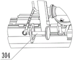
As shown in fig. 9-13, one end of the hydraulic cylinder 301 is fixedly mounted on the lower rotating rod 204, the other end is fixedly mounted on the compression head 304, the compression head 304 is slidably mounted on the curved rod 302, the curved rod 302 is fixedly mounted on the bottom plate base 101, one end of the curved rod connecting hose pipe 303 is connected to the curved rod 302, the other end is connected to the liquid filling bag 307, the pressing plate 305 is slidably mounted on the fixing rod 104, the positioning block 306 is fixedly mounted on the pressing plate 305, the liquid filling bag 307 is fixedly mounted on the positioning block 306, the guiding post 308 is slidably mounted on the horizontal rod 103, one end of the inclined plate 309 is fixedly mounted on the pressing plate 305, the other end is fixedly mounted on the guiding post 308, the vertical rack 310 is fixedly mounted on the guiding post 308, the vertical guiding plate 311 is fixedly mounted on the bottom plate base 101, the vertical rack 310 slides in the vertical guiding plate 311, the horizontal bag 312 is fixedly mounted on the sliding sleeve 213, the rotating gear, the rotary connecting base 315 is fixedly mounted on the base plate base 101, and the horizontal rack 313 is fixedly mounted on the clamping sliding table 201.
The working principle of the detection part 3 is that the horizontal liquid bag 312 is used for placing the casting 4, the casting 4 is fixedly positioned through the fixed clamping part 2, when the clamping sliding table 201 slides, firstly, the lower rotating rod 204 drives the hydraulic cylinder 301 to rotate, the hydraulic cylinder 301 drives the compression head 304 to extend and contract in the bent rod 302, liquid is pressed into the liquid filling bag 307 through the bent rod connecting hose pipe 303, then, the horizontal rack 313 and the rotating gear 314 are matched, the vertical rack 310 slides along the horizontal rack, the vertical rack 310 slides along the guide column 308, the guide column 308 slides along the pressure-fixing plate 305 through the inclined plate 309, the pressure-fixing plate 305 descends along the guide column, namely the liquid filling bag 307 is pressed to the surface of the casting 4, at this time, the liquid-filled bladder 307 is unchanged if the casting 4 is defect-free, and if the surface of the casting 4 is defect-free, such as dents or the like, the depression will compress the fluid-filled bag 307 and force the fluid in the fluid-filled bag 307 through the flexible hose 303 into the horizontal fluid bag 312. That is, when the liquid is present in the horizontal liquid pocket 312, it indicates that the casting 4 is defective. Thereby completing the surface inspection of the casting 4.
Claims (8)
1. The metal casting surface detection equipment comprises a detection frame, a fixed clamping part, a detection part and a casting, and is characterized in that the fixed clamping part comprises a clamping seat and a pushing seat, and the clamping seats can move oppositely through the driving of a power source set to fix and position the casting; the pushing seat can accelerate the process of positioning the casting; the detection part comprises a first detection head, a second detection head and a hydraulic cylinder; the first detection head is connected with the second detection head through a hose line, and the first detection head is also connected with the hydraulic cylinder through a hose line; when the clamping seat is used for fixing the casting, the hydraulic cylinder can be driven to carry out liquid filling operation on the first detection head, and when the clamping seat is used for fixing the casting, the detection head after liquid filling can be driven to extrude towards the surface of the casting; when the surface of the casting is provided with the recess, the recess can extrude the first detection head, and liquid in the first detection head is extruded into the second detection head, so that the defect of the casting is detected.
2. The metal casting surface detection equipment of claim 1, wherein the detection part further comprises a transposition part, the transposition part is arranged below the clamping seat and is used for changing the detected surface of the casting after the casting detects one surface; the left side and the right side of the clamping seat are symmetrically and slidably arranged on the bottom plate seat, and a pushing seat is slidably arranged on one of the clamping seats; a second detection head is fixedly arranged on the push seat and can penetrate through a central hole of the casting to place the casting; the clamping seat slides from two sides to the middle and drives the pushing seat to move forward, and the detection head II quickly penetrates through a central hole of the casting to realize the fixed positioning of the casting; the hydraulic cylinder is connected with the pushing seat through a bent rod; when the clamping seat slides, the push seat is utilized to drive the bent rod to compress in the hydraulic cylinder, liquid is conveyed to the first detection head, and the first detection head slides on the detection frame and descends to the surface of a casting fixedly positioned for detection.
3. The metal casting surface detection equipment of claim 2, wherein the clamping base comprises a clamping sliding table, a right nut base is fixedly mounted on the clamping sliding table, the right nut base is slidably mounted with a right screw rod, and a power source group is mounted on the right screw rod; the right nut rod is also provided with a third transmission gear, the third transmission gear is matched with the fourth transmission gear to drive the transmission rod to rotate, the transmission rod is provided with another group of third transmission gear and fourth transmission gear, and power is transmitted to the left nut rod through the matching of the other group of third transmission gear and the other group of fourth transmission gear; a clamping sliding table is arranged on the left nut rod; the clamping sliding table is driven to slide on the detection frame by the simultaneous rotation of the left nut rod and the nut rod; the clamping sliding table is fixedly provided with a side fixing seat, and a sliding sleeve of the pushing seat is slidably arranged in the side fixing seat.
4. The metal casting surface detection equipment of claim 3, wherein the push seat further comprises a grooved connecting rod, one end of the grooved connecting rod is rotatably mounted on the base plate seat, the other end of the grooved connecting rod is slidably connected with a lower rotating rod, the lower rotating rod is fixedly mounted on the clamping sliding table, the lower rotating rod is connected with the bent rod, an upper rotating rod is further slidably mounted on the grooved connecting rod, a connecting seat is arranged on the upper rotating rod, and the connecting seat is slidably mounted on the guide rod; the clamping table slides to drive the connecting rod with the groove to rotate, the connecting rod with the groove drives the connecting seat to move, the connecting seat pushes the sliding sleeve to move forward, and a second detection head is fixedly mounted on the sliding sleeve.
5. The apparatus as claimed in claim 2, wherein the first detection head comprises a liquid-filled bag and a horizontal rack, the liquid-filled bag is connected with a hydraulic cylinder through a hose line, the liquid-filled bag is arranged on a pressing plate through a positioning block, the pressing plate is slidably mounted on a fixing rod, and the pressing plate is slidably mounted on a guide column through an inclined plate; one end of the guide column is slidably arranged on the horizontal rod, and the other end of the guide column is fixedly arranged on the vertical rack; the horizontal rack is fixedly arranged on the clamping sliding table, the rotating gear is also arranged on the bottom plate seat, the clamping sliding table drives the horizontal rack to move, the horizontal rack is matched with the rotating gear, and the rotating gear is matched with the vertical rack so as to drive the pressing plate to slide up and down; the liquid filling bag is connected with the second detection head part, and liquid reaches the second detection head part along the hose passage by extruding the liquid filling bag.
6. The apparatus of claim 5, wherein the second sensing head comprises a horizontal bladder, the second horizontal bladder is fixedly mounted on the sliding sleeve, and the horizontal bladder is connected to the liquid bladder through a hose line.
7. The apparatus of claim 2, wherein the indexing member comprises a base support, a connecting shaft is mounted on the base support, a drive belt is disposed on the connecting shaft, and the drive belt is connected to a power source; universal joints are respectively installed at two ends of the connecting shaft and connected with the inner fixed shaft, side rubber wheels are fixedly installed on the inner fixed shaft, and the round casting rotates by an angle through the rotation of the side rubber wheels so as to change the detected surface.
8. The metal casting surface inspection device as defined in any one of claims 1 to 7, wherein the base plate base is further provided with springs, and the springs are arranged on the fixed columns and used for protecting the casting surface with a buffering force when inspecting the casting.
Priority Applications (1)
| Application Number | Priority Date | Filing Date | Title |
|---|---|---|---|
| CN202110739154.2A CN113406294B (en) | 2021-06-30 | 2021-06-30 | Metal casting surface detection equipment |
Applications Claiming Priority (1)
| Application Number | Priority Date | Filing Date | Title |
|---|---|---|---|
| CN202110739154.2A CN113406294B (en) | 2021-06-30 | 2021-06-30 | Metal casting surface detection equipment |
Publications (2)
| Publication Number | Publication Date |
|---|---|
| CN113406294A true CN113406294A (en) | 2021-09-17 |
| CN113406294B CN113406294B (en) | 2022-02-18 |
Family
ID=77680600
Family Applications (1)
| Application Number | Title | Priority Date | Filing Date |
|---|---|---|---|
| CN202110739154.2A Active CN113406294B (en) | 2021-06-30 | 2021-06-30 | Metal casting surface detection equipment |
Country Status (1)
| Country | Link |
|---|---|
| CN (1) | CN113406294B (en) |
Citations (13)
| Publication number | Priority date | Publication date | Assignee | Title |
|---|---|---|---|---|
| GB1172725A (en) * | 1966-03-25 | 1969-12-03 | United States Steel Corp | Apparatus and Method for Detecting Bulges in Continuous Casting. |
| US20150316508A1 (en) * | 2012-12-27 | 2015-11-05 | Posco | Apparatus and method for detecting inner defects of steel plate |
| BR112015025556A2 (en) * | 2013-04-17 | 2017-07-18 | Nippon Steel & Sumitomo Metal Corp | metal defect inspection method |
| CN206583827U (en) * | 2017-03-09 | 2017-10-24 | 伟杰科技(苏州)有限公司 | A kind of CT detection means of casting defect |
| CN207380028U (en) * | 2017-10-31 | 2018-05-18 | 厦门欣迈科技有限公司 | Metal column failure detector |
| CN108189354A (en) * | 2017-12-29 | 2018-06-22 | 重庆雷钜电子科技有限公司 | Moulding flatness detection mechanism |
| CN209117674U (en) * | 2018-11-28 | 2019-07-16 | 青州通达检测工程有限公司 | A kind of nondestructive-testing working table for metallic conduit |
| CN209525275U (en) * | 2018-11-08 | 2019-10-22 | 重庆三友机器制造有限责任公司 | Detection device is used in a kind of casting |
| CN210570453U (en) * | 2019-10-19 | 2020-05-19 | 温州宏泰无损检测有限公司 | Flatness detection device for pipe fitting machining |
| CN111323556A (en) * | 2020-03-10 | 2020-06-23 | 双峰县建设机械有限责任公司 | Casting clamp and surface defect detection device with same |
| CN111638314A (en) * | 2020-04-29 | 2020-09-08 | 高翠荣 | Diversified detection device in casting member surface |
| CN212179842U (en) * | 2020-08-03 | 2020-12-18 | 北京航天控制仪器研究所 | Detection apparatus for intelligent detection hemisphere part of hemisphere class |
| CN112504182A (en) * | 2021-01-08 | 2021-03-16 | 汪春香 | Alloy casting detection device utilizing water level change |
-
2021
- 2021-06-30 CN CN202110739154.2A patent/CN113406294B/en active Active
Patent Citations (13)
| Publication number | Priority date | Publication date | Assignee | Title |
|---|---|---|---|---|
| GB1172725A (en) * | 1966-03-25 | 1969-12-03 | United States Steel Corp | Apparatus and Method for Detecting Bulges in Continuous Casting. |
| US20150316508A1 (en) * | 2012-12-27 | 2015-11-05 | Posco | Apparatus and method for detecting inner defects of steel plate |
| BR112015025556A2 (en) * | 2013-04-17 | 2017-07-18 | Nippon Steel & Sumitomo Metal Corp | metal defect inspection method |
| CN206583827U (en) * | 2017-03-09 | 2017-10-24 | 伟杰科技(苏州)有限公司 | A kind of CT detection means of casting defect |
| CN207380028U (en) * | 2017-10-31 | 2018-05-18 | 厦门欣迈科技有限公司 | Metal column failure detector |
| CN108189354A (en) * | 2017-12-29 | 2018-06-22 | 重庆雷钜电子科技有限公司 | Moulding flatness detection mechanism |
| CN209525275U (en) * | 2018-11-08 | 2019-10-22 | 重庆三友机器制造有限责任公司 | Detection device is used in a kind of casting |
| CN209117674U (en) * | 2018-11-28 | 2019-07-16 | 青州通达检测工程有限公司 | A kind of nondestructive-testing working table for metallic conduit |
| CN210570453U (en) * | 2019-10-19 | 2020-05-19 | 温州宏泰无损检测有限公司 | Flatness detection device for pipe fitting machining |
| CN111323556A (en) * | 2020-03-10 | 2020-06-23 | 双峰县建设机械有限责任公司 | Casting clamp and surface defect detection device with same |
| CN111638314A (en) * | 2020-04-29 | 2020-09-08 | 高翠荣 | Diversified detection device in casting member surface |
| CN212179842U (en) * | 2020-08-03 | 2020-12-18 | 北京航天控制仪器研究所 | Detection apparatus for intelligent detection hemisphere part of hemisphere class |
| CN112504182A (en) * | 2021-01-08 | 2021-03-16 | 汪春香 | Alloy casting detection device utilizing water level change |
Also Published As
| Publication number | Publication date |
|---|---|
| CN113406294B (en) | 2022-02-18 |
Similar Documents
| Publication | Publication Date | Title |
|---|---|---|
| CN111948517B (en) | New energy automobile electronic control circuit board test system and test method | |
| CN214309875U (en) | Pipe ring rigidity test device | |
| CN111766143B (en) | Universal testing machine | |
| CN111992849A (en) | Automatic capturing and repair welding device after valve body casting production and working method thereof | |
| CN107627049B (en) | Be used for heat welding to detect Special heat welding device for equipment | |
| CN113406294B (en) | Metal casting surface detection equipment | |
| CN114295395A (en) | Auto-parts production detection device based on internet | |
| CN110757089A (en) | Clamping device suitable for pipe fittings with different pipe diameters | |
| CN212109942U (en) | Transmission shaft length measuring table | |
| CN113866034A (en) | Hardness quality detection equipment for aluminum magnesium alloy plate outgoing | |
| CN113399970A (en) | Full-automatic assembling equipment for high-voltage fuse | |
| CN111331272B (en) | Hub welding production line | |
| CN105067460A (en) | Self-adaptive hardness measuring machine | |
| CN111420891A (en) | Automatic wheel hub roundness detection and distribution device | |
| CN115112031A (en) | Method and equipment for measuring outer diameter and straightness of pipe | |
| CN111366350B (en) | Detection equipment for matching piece and use method thereof | |
| CN212674644U (en) | Ring blank pressing strength testing machine | |
| CN114130861A (en) | Straightening equipment | |
| CN112254993A (en) | Automatic test bed for hydraulic clamp brake adjuster | |
| CN210893044U (en) | Automatic detection equipment for finish turning process of shaft gear product | |
| CN107321634B (en) | Transmission shaft detection device | |
| CN110773983A (en) | Automatic press fitting equipment | |
| CN212963660U (en) | Weighing and drawing detection device for driving shaft | |
| CN110954415A (en) | Anti-violence test equipment for automobile glass | |
| CN219956491U (en) | Angle detection table for automobile backrest elbow assembly |
Legal Events
| Date | Code | Title | Description |
|---|---|---|---|
| PB01 | Publication | ||
| PB01 | Publication | ||
| SE01 | Entry into force of request for substantive examination | ||
| SE01 | Entry into force of request for substantive examination | ||
| GR01 | Patent grant | ||
| GR01 | Patent grant |