CN113293912A - Edge folding structure of assembled suspended ceiling and installation method - Google Patents
Edge folding structure of assembled suspended ceiling and installation method Download PDFInfo
- Publication number
- CN113293912A CN113293912A CN202110660824.1A CN202110660824A CN113293912A CN 113293912 A CN113293912 A CN 113293912A CN 202110660824 A CN202110660824 A CN 202110660824A CN 113293912 A CN113293912 A CN 113293912A
- Authority
- CN
- China
- Prior art keywords
- horizontal
- vertical
- strip
- bar
- section
- Prior art date
- Legal status (The legal status is an assumption and is not a legal conclusion. Google has not performed a legal analysis and makes no representation as to the accuracy of the status listed.)
- Pending
Links
Images


Classifications
-
- E—FIXED CONSTRUCTIONS
- E04—BUILDING
- E04B—GENERAL BUILDING CONSTRUCTIONS; WALLS, e.g. PARTITIONS; ROOFS; FLOORS; CEILINGS; INSULATION OR OTHER PROTECTION OF BUILDINGS
- E04B9/00—Ceilings; Construction of ceilings, e.g. false ceilings; Ceiling construction with regard to insulation
-
- E—FIXED CONSTRUCTIONS
- E04—BUILDING
- E04B—GENERAL BUILDING CONSTRUCTIONS; WALLS, e.g. PARTITIONS; ROOFS; FLOORS; CEILINGS; INSULATION OR OTHER PROTECTION OF BUILDINGS
- E04B9/00—Ceilings; Construction of ceilings, e.g. false ceilings; Ceiling construction with regard to insulation
- E04B9/006—Ceilings; Construction of ceilings, e.g. false ceilings; Ceiling construction with regard to insulation with means for hanging lighting fixtures or other appliances to the framework of the ceiling
-
- E—FIXED CONSTRUCTIONS
- E04—BUILDING
- E04B—GENERAL BUILDING CONSTRUCTIONS; WALLS, e.g. PARTITIONS; ROOFS; FLOORS; CEILINGS; INSULATION OR OTHER PROTECTION OF BUILDINGS
- E04B9/00—Ceilings; Construction of ceilings, e.g. false ceilings; Ceiling construction with regard to insulation
- E04B9/06—Ceilings; Construction of ceilings, e.g. false ceilings; Ceiling construction with regard to insulation characterised by constructional features of the supporting construction, e.g. cross section or material of framework members
-
- E—FIXED CONSTRUCTIONS
- E04—BUILDING
- E04B—GENERAL BUILDING CONSTRUCTIONS; WALLS, e.g. PARTITIONS; ROOFS; FLOORS; CEILINGS; INSULATION OR OTHER PROTECTION OF BUILDINGS
- E04B9/00—Ceilings; Construction of ceilings, e.g. false ceilings; Ceiling construction with regard to insulation
- E04B9/30—Ceilings; Construction of ceilings, e.g. false ceilings; Ceiling construction with regard to insulation characterised by edge details of the ceiling; e.g. securing to an adjacent wall
-
- F—MECHANICAL ENGINEERING; LIGHTING; HEATING; WEAPONS; BLASTING
- F21—LIGHTING
- F21V—FUNCTIONAL FEATURES OR DETAILS OF LIGHTING DEVICES OR SYSTEMS THEREOF; STRUCTURAL COMBINATIONS OF LIGHTING DEVICES WITH OTHER ARTICLES, NOT OTHERWISE PROVIDED FOR
- F21V21/00—Supporting, suspending, or attaching arrangements for lighting devices; Hand grips
- F21V21/02—Wall, ceiling, or floor bases; Fixing pendants or arms to the bases
Abstract
The invention discloses an edge folding structure of an assembled suspended ceiling and an installation method, and relates to the technical field of building decoration, wherein the edge folding structure comprises a fixed light trough line, an edge hanging plate and an edge folding line; the light trough line comprises a vertical plate, a light trough plate, a first horizontal plate and a second horizontal plate, wherein the light trough plate, the first horizontal plate and the second horizontal plate are connected with one side surface of the vertical plate; the edge-closing lines comprise first vertical lines, first horizontal lines and second horizontal lines, the first horizontal lines and the second horizontal lines are connected with one side faces of the first vertical lines, and the first horizontal lines, the first vertical lines and the second horizontal lines enclose second inserting grooves; one end of the side hanging plate is inserted into the first insertion groove, the other end of the side hanging plate is inserted into the second insertion groove, and the first vertical strip is fixed on one side wall body. The invention is convenient for installing the side hanging plate, and the side hanging plate does not need to be nailed, thereby having good appearance.
Description
Technical Field
The invention relates to the technical field of building decoration, in particular to an edge folding structure of an assembled suspended ceiling and an installation method.
Background
The suspended ceiling plays a role in decorating the top of an indoor building and is an indispensable part for indoor decoration.
The assembled suspended ceiling is a popular suspended ceiling form at present, and the assembled suspended ceiling can realize production completion with each part that the suspended ceiling needs to use in the mill, then transports to decorate the scene and carries out the composite mounting, and the construction is more simple and convenient, can greatly improve the efficiency of construction of decorating the scene to the job site is more clean and tidy and pleasing to the eye. The falling-level suspended ceiling refers to a falling-level suspended ceiling which is not on the same plane and is similar to a ladder, and in the home-mounted suspended ceiling, the common falling-level suspended ceiling shows the spaciousness of the space.
When the assembled suspended ceiling is folded, the last board edge hanging board is difficult to mount, no operation space exists, most of the board edges need to be nailed, the problem of nail hole exposure exists, and the assembled suspended ceiling is not attractive enough.
Therefore, it is necessary to solve the above-mentioned technical problems.
Disclosure of Invention
The invention aims to make up for the defects in the prior art, and provides an edge folding structure and an installation method of an assembled suspended ceiling, which are convenient for installing an edge hanging plate.
The embodiment of the invention provides an edge folding structure of an assembled ceiling, which comprises: the fixed lamp groove line, the side hanging plate and the side folding line are arranged on the upper surface of the lamp groove; the lamp groove lines comprise vertical plates, lamp groove plates, first horizontal plates and second horizontal plates, the lamp groove plates, the first horizontal plates and the second horizontal plates are arranged at intervals from top to bottom and are connected with one side face, close to one side wall body, of each vertical plate, lamp grooves for arranging lamp belts are formed in the lamp groove plates, and the first horizontal plates, the vertical plates and the second horizontal plates surround a first inserting groove; the edge folding lines comprise first vertical strips, first horizontal strips and second horizontal strips, the first horizontal strips and the second horizontal strips are arranged at intervals and are connected with one side surface of the first vertical strip, which is far away from the wall body on one side, and the first horizontal strips, the first vertical strips and the second horizontal strips surround a second inserting groove; one end of the side hanging plate is inserted into the first insertion groove, the other end of the side hanging plate is inserted into the second insertion groove, and the first vertical strip is fixed on one side wall body.
Optionally, the edge closing structure of the assembled ceiling further comprises an edge hanging piece, the edge hanging piece is made of a section bar, the edge hanging piece comprises a third horizontal bar, a second vertical bar and a fourth horizontal bar, one end of the third horizontal bar is connected with the bottom end of the second vertical bar, the top end of the second vertical bar is connected with one end of the fourth horizontal bar, the third horizontal bar and the fourth horizontal bar are located on the same side of the second vertical bar, and the third horizontal bar, the second vertical bar and the fourth horizontal bar enclose a third inserting groove; the other end of the side hanging plate is provided with a first protruding part, the first protruding part is inserted into the third insertion groove in a matching mode, and the third horizontal bar, the second vertical bar and the fourth horizontal bar are inserted into the second insertion groove in a inserting mode.
Optionally, the first protrusion is fixed to the side hanger by bonding.
Optionally, the side hanging piece further comprises a third vertical bar and a bent bar, the bottom end of the third vertical bar is connected with the other end of the fourth horizontal bar, the top end of the third vertical bar is connected with one end of the bent bar, the fourth horizontal bar and the bent bar are located on the same side of the third vertical bar, and the fourth horizontal bar, the third vertical bar and the bent bar enclose a fourth inserting groove; the first horizontal bar is inserted into the fourth insertion groove, and the bending bar presses the first horizontal bar onto the fourth horizontal bar.
Optionally, the fabricated ceiling edge folding structure further comprises a panel, a vertical frame plate, a first hanging and connecting piece, a second hanging and connecting piece, a horizontal vertical frame plate and a vertical frame connecting piece; the panel is hung on the top wall; the first hanging and connecting piece is fixed at the outer end of the panel, the second hanging and connecting piece is fixed at the top end of the vertical frame plate, the second hanging and connecting piece is hung and connected to the first hanging and connecting piece, one end, close to a wall body on one side, of the horizontal vertical frame plate is fixedly connected with the bottom end of the vertical frame plate through the vertical frame and connecting piece, and the horizontal vertical frame plate and the panel are located on the same side of the vertical frame plate; the first horizontal plate of the light trough line is fixedly connected with the other end, far away from a wall body, of the horizontal vertical frame plate, the other end of the horizontal vertical frame plate is abutted against one side face of the vertical plate, and the top face of the first horizontal plate is attached to the bottom face of the other end of the horizontal vertical frame plate.
Optionally, the grudging post connecting piece includes first horizontal segment and first vertical section, the one end of first horizontal segment with the bottom of first vertical section links to each other, the top surface of first horizontal segment with the bottom surface of horizontal grudging post board one end paste and first horizontal segment with horizontal grudging post board fixed connection, the bottom surface of vertical grudging post board with the top surface of horizontal grudging post board one end pastes, a side of first vertical segment with the terminal surface of horizontal grudging post board one end with the bottom of vertical grudging post board side pastes mutually, first vertical segment with vertical grudging post board fixed connection.
Optionally, the first hanging piece comprises a fifth horizontal bar, a fourth vertical bar, a sixth horizontal bar, a fifth vertical bar and a seventh horizontal bar, one end of the fifth horizontal bar is connected with the top end of the fourth vertical bar, the bottom end of the fourth vertical bar is connected with one end of the sixth horizontal bar, the other end of the sixth horizontal bar is connected with the top end of the fifth vertical bar, the bottom end of the fifth vertical bar is connected with the middle part of the seventh horizontal bar, the fifth horizontal bar and the sixth horizontal bar are located on the same side of the fourth vertical bar, and the fifth horizontal bar, the fourth vertical bar and the sixth horizontal bar enclose a fifth inserting groove; the second hanging piece comprises an eighth horizontal bar and a sixth vertical bar, and one end of the eighth horizontal bar is connected with the top end of the sixth vertical bar; the outer end of the panel is provided with a second protruding part which is matched and plugged in the fifth plugging groove, the side surface of the panel below the second protruding part is pasted with the fifth vertical strip, the top surface of the seventh horizontal strip on one side of the fifth vertical strip is pasted with the bottom surface of the panel, and the fifth horizontal strip is fixedly connected with the top surface of the panel; one side surface of the sixth vertical strip is fixedly connected with the top end of one side surface of the vertical frame plate, the eighth horizontal strip is arranged at an interval with the top surface of the vertical frame plate, the eighth horizontal strip, the sixth vertical strip and the top surface of the vertical frame plate enclose a sixth inserting groove, and the seventh horizontal strip positioned on the other side of the fifth vertical strip is inserted into the sixth inserting groove in a matched mode.
Optionally, the top surface fixedly connected with at least one row of pendant of panel, top wall fixedly connected with fossil fragments subassembly, at least one row of pendant articulate in fossil fragments subassembly.
Optionally, the keel assembly comprises a plurality of main keels and a plurality of cross keels, and each main keel comprises a main keel body and a plurality of hanging bodies arranged at the bottom of the main keel body at intervals; the hanging body comprises a second vertical section, a second horizontal section and a third vertical section, the top end of the second vertical section is connected with the bottom of the main keel body, the bottom end of the second vertical section is connected with one end of the second horizontal section, the other end of the second horizontal section is connected with one side of the third vertical section, the top end and the bottom end of the third vertical section respectively protrude out of the second horizontal section, and a groove body is formed between the top end of the third vertical section and the second vertical section as well as between the top end of the second vertical section and the second horizontal section; the auxiliary keel comprises a seventh vertical strip, a ninth horizontal strip, a tenth horizontal strip, a first hemming strip and a second hemming strip, the top end of the seventh vertical strip is connected with one end of the ninth horizontal strip, the bottom end of the seventh vertical strip is connected with one end of the tenth horizontal strip, the other end of the ninth horizontal strip is connected with the top end of the first hemming strip, and the other end of the tenth horizontal strip is connected with the bottom end of the second hemming strip; the main keels are arranged between the wall body on one side and the wall body on the other side at intervals, main keel bodies of the main keels are perpendicular to the wall body on one side and the wall body on the other side, and the main keel bodies of the main keels are fixed on a top wall through expansion bolts; the auxiliary keels are perpendicular to main keel bodies of the main keels and are respectively hung on multiple rows of hanging bodies opposite to the main keels, the ninth horizontal bar is supported at the top end of the third vertical section, the seventh vertical bar is positioned on one side, far away from the second vertical section, of the third vertical section, and the first edge rolling strip is accommodated in the groove body; the pendant comprises a third horizontal section, a fourth vertical section, a fourth horizontal section and a curled edge section, the bottom end of the fourth vertical section is connected with one end of the third horizontal section, the top end of the fourth vertical section is connected with one end of the fourth horizontal section, the top end of the curled edge section is connected with the other end of the fourth horizontal section, and the third horizontal section, the fourth horizontal section and the curled edge section are respectively positioned at two sides of the fourth vertical section; the top surface of each panel is provided with at least one strip-shaped groove parallel to the auxiliary keel, and the third horizontal sections of at least one row of the hangers are respectively embedded and fixed in the at least one strip-shaped groove in an adhering manner; the fourth horizontal section of the at least one row of hangers is respectively supported on a ninth horizontal strip of the multiple auxiliary keels, the hemming section is located on one side, away from the seventh vertical strip, of the first hemming strip, and the fourth vertical section is located on one side, away from the first hemming strip, of the seventh vertical strip.
The embodiment of the invention also provides an installation method of the edge closing structure of the fabricated suspended ceiling, wherein the edge closing structure of the fabricated suspended ceiling is the edge closing structure of the fabricated suspended ceiling, and the installation method comprises the following steps: inserting the other end of the side hanging plate into the second inserting groove of the side line; lifting the side hanging plate and the edge folding line integrally to insert one end of the side hanging plate into the first insertion groove of the lamp groove line; and fixing the first vertical strip of the edge-closing line on a side wall body.
The edge folding structure of the assembled ceiling provided by the embodiment of the invention comprises a first horizontal plate and a second horizontal plate which are arranged at intervals and connected with one side surface of a vertical plate close to one side wall body, the first horizontal plate, the vertical plate and the second horizontal plate enclose a first inserting groove, the edge folding line comprises a first horizontal bar and a second horizontal bar which are arranged at intervals and connected with one side surface of the first vertical bar far away from one side wall body, the first horizontal bar, the first vertical bar and the second horizontal bar enclose a second inserting groove, when the edge folding structure of the assembled ceiling is installed, the other end of the edge hanging plate can be firstly connected with the second inserting groove of the edge folding line in an inserting manner, then the edge hanging plate is lifted upwards and the edge folding line insert one end of the edge hanging plate into the first inserting groove of the light groove line, and finally the first vertical bar of the edge folding line is fixed on one side wall body, so that the installation of the edge hanging plate can be completed, and the side hanging plate does not need nailing, and the appearance is good.
Drawings
In order to more clearly illustrate the technical solution of the present invention, the drawings needed to be used in the description of the present invention will be briefly introduced below, and it is apparent that the drawings described below are only some embodiments of the present invention, and it is obvious for those skilled in the art that other drawings can be obtained according to the drawings without inventive labor.
Fig. 1 is a schematic structural diagram of an edge folding structure of an assembled ceiling provided in an embodiment of the present invention.
Fig. 2 is an enlarged view of a point a in fig. 1.
Fig. 3 is an enlarged view at B in fig. 1.
Fig. 4 is an enlarged view at C in fig. 1.
Fig. 5 is an enlarged view at D in fig. 1.
Detailed Description
The technical solutions in the present invention will be described clearly and completely with reference to the accompanying drawings, and it is obvious that the described embodiments are some, not all embodiments of the present invention. All other embodiments, which can be obtained by a person skilled in the art without any inventive step based on the embodiments of the present invention, shall fall within the scope of protection of the present invention.
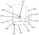
As shown in fig. 1-3, an embodiment of the present invention provides an assembled ceiling edge folding structure 10, including: a fixed light trough line 100, an edge hanger plate 200 and an edge trimming line 300. The light trough line 100 comprises a vertical plate 110, a light trough plate 120, a first horizontal plate 130 and a second horizontal plate 140, wherein the light trough plate 120, the first horizontal plate 130 and the second horizontal plate 140 are arranged at intervals from top to bottom and are connected with one side surface, close to one side wall body, of the vertical plate 110, a light trough 121 for arranging a light strip 400 is formed on the light trough plate 120, and a first inserting groove 150 is defined by the first horizontal plate 130, the vertical plate 110 and the second horizontal plate 140. The trimming line 300 comprises a first vertical bar 310, a first horizontal bar 320 and a second horizontal bar 330, the first horizontal bar 320 and the second horizontal bar 330 are arranged at intervals and connected with one side surface of the first vertical bar 310, which is far away from a wall body, and the first horizontal bar 320, the first vertical bar 310 and the second horizontal bar 330 enclose a second inserting groove 340. One end of the side hanging plate 200 is inserted into the first insertion groove 150, the other end of the side hanging plate 200 is inserted into the second insertion groove 340, and the first vertical bar 310 is fixed to a side wall.
The assembled ceiling edge folding structure 10 provided by the embodiment of the invention is characterized in that the light groove line 100 comprises a first horizontal plate 130 and a second horizontal plate 140 which are arranged at intervals and connected with one side surface of the vertical plate 110 close to one side wall body, the first horizontal plate 130, the vertical plate 110 and the second horizontal plate 140 enclose a first inserting groove 150, the edge folding line 300 comprises a first horizontal bar 320 and a second horizontal bar 330 which are arranged at intervals and connected with one side surface of the first vertical bar 310 far away from one side wall body, the first horizontal bar 320, the first vertical bar 310 and the second horizontal bar 330 enclose a second inserting groove 340, when the assembled ceiling edge folding structure 10 is installed, the other end of the edge hanging plate 200 can be firstly inserted and connected with the second inserting groove 340 of the edge folding line 300, then the upper edge hanging plate 200 and the edge folding line 300 can fix one end of the edge hanging plate 200 in the first inserting groove 150 of the light groove line 100, and finally the first vertical bar 310 of the edge folding line 300 is fixed on one side to complete the installation of the wall body, the side hanging plate 200 is convenient to install, nailing is not needed on the side hanging plate 200, and the appearance is attractive.
As a preferred implementation manner of the embodiment of the present invention, as shown in fig. 3, the fabricated ceiling edge folding structure 10 further includes an edge hanging piece 500, the edge hanging piece 500 is made of a profile, the edge hanging piece 500 includes a third horizontal bar 510, a second vertical bar 520 and a fourth horizontal bar 530, one end of the third horizontal bar 510 is connected to a bottom end of the second vertical bar 520, a top end of the second vertical bar 520 is connected to one end of the fourth horizontal bar 530, the third horizontal bar 510 and the fourth horizontal bar 530 are located on the same side of the second vertical bar 520, and the third horizontal bar 510, the second vertical bar 520 and the fourth horizontal bar 530 enclose a third insertion groove 540; the other end of the side hanging plate 200 has a first protrusion 210, the first protrusion 210 is inserted into the third insertion groove 540 in a matching manner, and the third horizontal bar 510, the second vertical bar 520 and the fourth horizontal bar 530 are inserted into the second insertion groove 340. In this embodiment, the other end of the side hanging plate 200 is inserted into the edge folding line 300 through the side hanging piece 500 made of the sectional material, so that the connection strength between the side hanging plate 200 and the edge folding line 300 can be enhanced, and the deformation of the side hanging plate 200 can be reduced.
In a preferred embodiment of the present invention, the first protrusion 210 is bonded and fixed to the side hanger 500. In this embodiment, the first protrusion 210 of the side hanger 200 is fixed to the side hanger 500 by bonding, so that the connection stability between the side hanger 200 and the side hanger 500 and the edge strip 300 can be enhanced, the fixing and connection are simple, and the construction efficiency can be improved.
As a preferred implementation manner of the embodiment of the present invention, as shown in fig. 3, the side hanging member 500 further includes a third vertical bar 550 and a bent bar 560, a bottom end of the third vertical bar 550 is connected to the other end of the fourth horizontal bar 530, a top end of the third vertical bar 550 is connected to one end of the bent bar 560, the fourth horizontal bar 530 and the bent bar 560 are located on the same side of the third vertical bar 550, and the fourth horizontal bar 530, the third vertical bar 550 and the bent bar 560 define a fourth inserting slot 570; the first horizontal bar 320 is inserted into the fourth insertion groove 570, and the bending bar 560 presses the first horizontal bar 320 against the fourth horizontal bar 530. In this embodiment, the side hanger 500 further comprises a third vertical bar 550 and a bending bar 560, so that the side hanger 500 is conveniently matched and positioned when being inserted into the side line folding line 300 of the side wall, and the bending bar 560 can also tightly press the side line folding line 300 of the side wall and the side hanger 500, thereby enhancing the stability of the connection between the side line folding line 300 of the side wall and the side hanger 500.
As a preferred implementation manner of the embodiment of the present invention, as shown in fig. 1, the fabricated suspended ceiling edge folding structure 10 further includes a panel 600, a vertical frame plate 700, a first hanging piece 800, a second hanging piece 900, a horizontal vertical frame plate 1000, and a vertical frame connecting piece 1100; the panel 600 is suspended from a top wall; the first hanging piece 800 is fixed at the outer end of the panel 600, the second hanging piece 900 is fixed at the top end of the vertical upright frame plate 700, the second hanging piece 900 is hung on the first hanging piece 800, one end of the horizontal upright frame plate 1000 close to one side wall body is fixedly connected with the bottom end of the vertical upright frame plate 700 through the upright frame connecting piece 1100, and the horizontal upright frame plate 1000 and the panel 600 are positioned at the same side of the vertical upright frame plate 700; the first horizontal plate 130 of the light trough line 100 is fixedly connected with the other end of the horizontal upright frame plate 1000, which is far away from the wall body on one side, the other end of the horizontal upright frame plate 1000 is abutted against one side surface of the vertical plate 110, and the top surface of the first horizontal plate 130 is attached to the bottom surface of the other end of the horizontal upright frame plate 1000. In this embodiment, by suspending the panel 600 from the top wall, the second hanging member 900 fixedly connected to the top end of the vertical upright frame plate 700 is hung to the first hanging member 800 fixedly connected to the outer end of the panel 600, the end of the horizontal upright frame plate 1000 close to one side wall is fixedly connected to the bottom end of the vertical upright frame plate 700 through the upright frame connecting member 1100, and the light trough line 100 is fixedly connected to the other end of the horizontal upright frame plate 1000 away from one side wall through the first horizontal plate 130, so that the light trough line 100 is conveniently fixed.
As a preferred implementation manner of the embodiment of the present invention, as shown in fig. 2, the upright frame connecting member 1100 includes a first horizontal segment 1110 and a first vertical segment 1120, one end of the first horizontal segment 1110 is connected to a bottom end of the first vertical segment 1120, a top surface of the first horizontal segment 1110 is attached to a bottom surface of one end of the horizontal upright frame plate 1000, the first horizontal segment 1110 is fixedly connected to the horizontal upright frame plate 1000, a bottom surface of the vertical upright frame plate 700 is attached to a top surface of one end of the horizontal upright frame plate 1000, a side surface of the first vertical segment 1120 is attached to an end surface of one end of the horizontal upright frame plate 1000 and a bottom end of a side surface of the vertical upright frame plate 700, and the first vertical segment 1120 is fixedly connected to the vertical upright frame plate 700. In this embodiment, the vertical stile 700 and the horizontal stile 1000 can be cut on site according to different designs to adjust the size of the vertical stile 700 and the horizontal stile 1000, and the adaptability is stronger.
As a preferred implementation manner of the embodiment of the present invention, as shown in fig. 4, the first hanging member 800 includes a fifth horizontal bar 810, a fourth vertical bar 820, a sixth horizontal bar 830, a fifth vertical bar 840 and a seventh horizontal bar 850, one end of the fifth horizontal bar 810 is connected to a top end of the fourth vertical bar 820, a bottom end of the fourth vertical bar 820 is connected to one end of the sixth horizontal bar 830, the other end of the sixth horizontal bar 830 is connected to a top end of the fifth vertical bar 840, a bottom end of the fifth vertical bar 840 is connected to a middle portion of the seventh horizontal bar 850, the fifth horizontal bar 810 and the sixth horizontal bar 830 are located on the same side of the fourth vertical bar 820, and the fifth horizontal bar 810, the fourth vertical bar 820 and the sixth horizontal bar 830 enclose a fifth splicing groove 860; the second hanging piece 900 comprises an eighth horizontal bar 910 and a sixth vertical bar 920, and one end of the eighth horizontal bar 910 is connected with the top end of the sixth vertical bar 920; the outer end of the panel 600 is provided with a second protruding portion 610, the second protruding portion 610 is fittingly inserted into the fifth insertion groove 860, the side surface of the panel 600 located below the second protruding portion 610 is attached to the fifth vertical bar 840, the top surface of the seventh horizontal bar 850 located on one side of the fifth vertical bar 840 is attached to the bottom surface of the panel 600, and the fifth horizontal bar 810 is fixedly connected to the top surface of the panel 600; one side surface of the sixth vertical bar 920 is fixedly connected with the top end of one side surface of the vertical frame plate 700, the eighth horizontal bar 910 is arranged at an interval with the top surface of the vertical frame plate 700, the eighth horizontal bar 910, the sixth vertical bar 920 and the top surface of the vertical frame plate 700 define a sixth insertion groove 1200, and the seventh horizontal bar 850 positioned at the other side of the fifth vertical bar 840 is inserted into the sixth insertion groove 1200 in a matching manner. In this embodiment, the second hanging member 900 is hung on the seventh horizontal bar 850 through the eighth horizontal bar 910, and the seventh horizontal bar 850 of the first hanging member 800 on the other side of the fifth vertical bar 840 is inserted into the sixth insertion groove 1200 in a matching manner, so that the relative movement between the first hanging member 800 and the second hanging member 900 can be limited, and the vertical upright frame plate 700 can be stably hung on the panel 600.
As a preferred implementation manner of the embodiment of the present invention, as shown in fig. 1, at least one row of hanging members 1300 is fixedly connected to a top surface of the panel 600, a keel assembly 1400 is fixedly connected to the top wall, and the at least one row of hanging members 1300 is hung on the keel assembly 1400. In this embodiment, the panel 600 is hung on the keel assembly 1400 fixed on the top wall through the hanging member 1300, and the installation is simple and the construction efficiency is high.
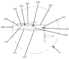
As a preferred embodiment of the present invention, as shown in fig. 5, the keel assembly 1400 includes a plurality of main keels 1410 and a plurality of cross keels 1420, and each main keel 1410 includes a main keel body 1411 and a plurality of hitching bodies 1412 spaced apart from the bottom of the main keel body 1411; the hanging body 1412 comprises a second vertical section 1413, a second horizontal section 1414 and a third vertical section 1415, wherein the top end of the second vertical section 1413 is connected with the bottom of the main keel body 1411, the bottom end of the second vertical section 1413 is connected with one end of the second horizontal section 1414, the other end of the second horizontal section 1414 is connected with one side of the third vertical section 1415, the top end and the bottom end of the third vertical section 1415 respectively protrude out of the second horizontal section 1414, and a groove 1416 is formed between the top end of the third vertical section 1415 and the second horizontal section 1414 and the second vertical section 1413; the cross runner 1420 includes a seventh vertical bar 1421, a ninth horizontal bar 1422, a tenth horizontal bar 1423, a first hemming bar 1424, and a second hemming bar 1425, a top end of the seventh vertical bar 1421 is connected to one end of the ninth horizontal bar 1422, a bottom end of the seventh vertical bar 1421 is connected to one end of the tenth horizontal bar 1423, another end of the ninth horizontal bar 1422 is connected to a top end of the first hemming bar 1424, and another end of the tenth horizontal bar 1423 is connected to a bottom end of the second hemming bar 1425; the main keels 1410 are arranged between one side wall body and the other side wall body at intervals, main keel bodies 1411 of the main keels 1410 are perpendicular to the one side wall body and the other side wall body, and the main keel bodies 1411 of the main keels 1410 are fixed on a top wall through expansion bolts; the multiple cross runners 1420 are perpendicular to the main runner bodies 1411 of the multiple main runners 1410 and are respectively hung on the multiple rows of hanging bodies 1412 facing the multiple main runners 1410, the ninth horizontal strip 1422 is supported at the top end of the third vertical section 1415, the seventh vertical strip 1421 is located at the side of the third vertical section 1415 far away from the second vertical section 1413, and the first curling strip 1424 is accommodated in the groove 1416; the pendant 1300 comprises a third horizontal segment 1310, a fourth vertical segment 1320, a fourth horizontal segment 1330 and a curled segment 1340, wherein the bottom end of the fourth vertical segment 1320 is connected with one end of the third horizontal segment 1310, the top end of the fourth vertical segment 1320 is connected with one end of the fourth horizontal segment 1330, the top end of the curled segment 1340 is connected with the other end of the fourth horizontal segment 1330, and the third horizontal segment 1310, the fourth horizontal segment 1330 and the curled segment 1340 are respectively positioned at two sides of the fourth vertical segment 1320; the top surface of each panel 600 is provided with at least one strip-shaped groove 620 parallel to the furring channel 1420, and the third horizontal segments 1310 of at least one row of the hanging members 1300 are respectively embedded and fixed in the at least one strip-shaped groove 620 in an adhering manner; the fourth horizontal segment 1330 of the at least one row of hangers 1300 is supported on the ninth horizontal strips 1422 of the cross runners 1420, respectively, and the hemmed segment 1340 is located on the side of the first hemmed strip 1424 away from the seventh vertical strip 1421, and the fourth vertical segment 1320 is located on the side of the seventh vertical strip 1421 away from the first hemmed strip 1424. In this embodiment, by providing that the main keel 1410 includes a plurality of hanging bodies 1412 connected to the bottom of the main keel body 1411, the hanging bodies 1412 include a slot 1416 surrounded by the top end of the third vertical section 1415, the second horizontal section 1414 and the second vertical section 1413, the cross keel 1420 is provided to include a seventh vertical strip 1421, a ninth horizontal strip 1422, a tenth horizontal strip 1423, a first hemming strip 1424 and a second hemming strip 1425, the ninth horizontal strip 1422 is supported on the top end of the third vertical section 1415, the seventh vertical strip 1421 is located on the side of the third vertical section 1415 away from the second vertical section 1413, the first hemming strip 1424 is received in the slot 1416, so that the cross keel 1420 can be easily hung on the main keel 1410, the hanging member 1300 includes a third horizontal section 1310, a fourth vertical section 1320, a fourth horizontal section 1330 and a hemming strip 1340, the third horizontal section 1420 of the hanging member 1300 is embedded and fixed in the slot 620 of the panel 600, and the fourth horizontal strip 1330 of the hanging member 1300 is supported on the ninth horizontal strip 1422, and the hemming section 1340 is located at a side of the first hemming strip 1424 away from the seventh vertical strip 1421, and the fourth vertical section 1320 is located at a side of the seventh vertical strip 1421 away from the first hemming strip 1424, so that the panel 600 can be easily hung on the cross runner 1420, and the installation efficiency is high.
As a preferred implementation manner of the embodiment of the present invention, the fifth horizontal bar 810 is fixedly connected to the top surface of the panel 600 by a screw, and one side surface of the sixth vertical bar 920 is fixedly connected to the top end of one side surface of the vertical frame plate 700 by a screw. In this embodiment, the first hanging member 800 and the second hanging member 900 are simply and firmly fixed to the panel 600 and the vertical mullion panel 700, respectively.
As a preferred embodiment of the present invention, the first horizontal segment 1110 is fixedly connected to the horizontal upright frame plate 1000 by screws, and the first vertical segment 1120 is fixedly connected to the vertical upright frame plate 700 by screws. In this embodiment, the vertical frame connecting member 1100 is simply and firmly fixed to the vertical frame plate 700 and the horizontal frame plate 1000, respectively.
As a preferred implementation manner of the embodiment of the present invention, the first vertical bar 310 is fixedly connected to a side wall through a nail. In this embodiment, the edge-closing line 300 is simply and firmly fixed to the wall body on one side.
The embodiment of the invention also provides an installation method of the fabricated ceiling edge folding structure, the fabricated ceiling edge folding structure is the fabricated ceiling edge folding structure 10, as shown in fig. 1-3, and the installation method comprises the following steps:
inserting the other end of the side hanging plate 200 into the second inserting groove 340 of the side line 300;
lifting the side hanging plate 200 and the edge folding line 300 as a whole to insert one end of the side hanging plate 200 into the first insertion groove 150 of the light trough line 100;
fixing the first vertical bar 310 of the edge trimming strip 300 to a side wall.
The assembled ceiling edge folding structure 10 provided by the embodiment of the invention is characterized in that the light groove line 100 comprises a first horizontal plate 130 and a second horizontal plate 140 which are arranged at intervals and connected with one side surface of the vertical plate 110 close to one side wall body, the first horizontal plate 130, the vertical plate 110 and the second horizontal plate 140 enclose a first inserting groove 150, the edge folding line 300 comprises a first horizontal bar 320 and a second horizontal bar 330 which are arranged at intervals and connected with one side surface of the first vertical bar 310 far away from one side wall body, the first horizontal bar 320, the first vertical bar 310 and the second horizontal bar 330 enclose a second inserting groove 340, when the assembled ceiling edge folding structure 10 is installed, the other end of the edge hanging plate 200 can be firstly inserted and connected with the second inserting groove 340 of the edge folding line 300, then the upper edge hanging plate 200 and the edge folding line 300 can fix one end of the edge hanging plate 200 in the first inserting groove 150 of the light groove line 100, and finally the first vertical bar 310 of the edge folding line 300 is fixed on one side to complete the installation of the wall body, the side hanging plate 200 is convenient to install, nailing is not needed on the side hanging plate 200, and the appearance is attractive.
While the invention has been described with reference to specific embodiments, the invention is not limited thereto, and various equivalent modifications and substitutions can be easily made by those skilled in the art within the technical scope of the invention. Therefore, the protection scope of the present invention shall be subject to the protection scope of the claims.
Claims (10)
1. The utility model provides an edge structure is received to assembled furred ceiling which characterized in that includes: the fixed lamp groove line, the side hanging plate and the side folding line are arranged on the upper surface of the lamp groove; the lamp groove lines comprise vertical plates, lamp groove plates, first horizontal plates and second horizontal plates, the lamp groove plates, the first horizontal plates and the second horizontal plates are arranged at intervals from top to bottom and are connected with one side face, close to one side wall body, of each vertical plate, lamp grooves for arranging lamp belts are formed in the lamp groove plates, and the first horizontal plates, the vertical plates and the second horizontal plates surround a first inserting groove; the edge folding lines comprise first vertical strips, first horizontal strips and second horizontal strips, the first horizontal strips and the second horizontal strips are arranged at intervals and are connected with one side surface of the first vertical strip, which is far away from the wall body on one side, and the first horizontal strips, the first vertical strips and the second horizontal strips surround a second inserting groove; one end of the side hanging plate is inserted into the first insertion groove, the other end of the side hanging plate is inserted into the second insertion groove, and the first vertical strip is fixed on one side wall body.
2. The fabricated ceiling edging structure according to claim 1, further comprising an edging member, wherein the edging member is made of a profile, the edging member comprises a third horizontal bar, a second vertical bar and a fourth horizontal bar, one end of the third horizontal bar is connected with the bottom end of the second vertical bar, the top end of the second vertical bar is connected with one end of the fourth horizontal bar, the third horizontal bar and the fourth horizontal bar are located on the same side of the second vertical bar, and the third horizontal bar, the second vertical bar and the fourth horizontal bar enclose a third insertion groove; the other end of the side hanging plate is provided with a first protruding part, the first protruding part is inserted into the third insertion groove in a matching mode, and the third horizontal bar, the second vertical bar and the fourth horizontal bar are inserted into the second insertion groove in a inserting mode.
3. The fabricated ceiling trim structure of claim 2, wherein the first protrusion is adhesively secured to the side hanger.
4. The fabricated ceiling edge folding structure according to claim 3, wherein the edge hanging piece further comprises a third vertical strip and a bent strip, the bottom end of the third vertical strip is connected with the other end of the fourth horizontal strip, the top end of the third vertical strip is connected with one end of the bent strip, the fourth horizontal strip and the bent strip are located on the same side of the third vertical strip, and the fourth horizontal strip, the third vertical strip and the bent strip enclose a fourth inserting groove; the first horizontal bar is inserted into the fourth insertion groove, and the bending bar presses the first horizontal bar onto the fourth horizontal bar.
5. The fabricated ceiling trim structure of claim 4, further comprising a panel, a vertical upright frame plate, a first hanging member, a second hanging member, a horizontal upright frame plate, and an upright frame connecting member; the panel is hung on the top wall; the first hanging and connecting piece is fixed at the outer end of the panel, the second hanging and connecting piece is fixed at the top end of the vertical frame plate, the second hanging and connecting piece is hung and connected to the first hanging and connecting piece, one end, close to a wall body on one side, of the horizontal vertical frame plate is fixedly connected with the bottom end of the vertical frame plate through the vertical frame and connecting piece, and the horizontal vertical frame plate and the panel are located on the same side of the vertical frame plate; the first horizontal plate of the light trough line is fixedly connected with the other end, far away from a wall body, of the horizontal vertical frame plate, the other end of the horizontal vertical frame plate is abutted against one side face of the vertical plate, and the top face of the first horizontal plate is attached to the bottom face of the other end of the horizontal vertical frame plate.
6. The fabricated ceiling edging structure according to claim 5, wherein the upright frame connecting piece comprises a first horizontal section and a first vertical section, one end of the first horizontal section is connected with the bottom end of the first vertical section, the top surface of the first horizontal section is attached to the bottom surface of one end of the horizontal upright frame plate, the first horizontal section is fixedly connected with the horizontal upright frame plate, the bottom surface of the vertical upright frame plate is attached to the top surface of one end of the horizontal upright frame plate, one side surface of the first vertical section is attached to the end surface of one end of the horizontal upright frame plate and the bottom end of one side surface of the vertical upright frame plate, and the first vertical section is fixedly connected with the vertical upright frame plate.
7. The fabricated ceiling trimming structure according to claim 6, wherein the first hanging piece comprises a fifth horizontal bar, a fourth vertical bar, a sixth horizontal bar, a fifth vertical bar and a seventh horizontal bar, one end of the fifth horizontal bar is connected with the top end of the fourth vertical bar, the bottom end of the fourth vertical bar is connected with one end of the sixth horizontal bar, the other end of the sixth horizontal bar is connected with the top end of the fifth vertical bar, the bottom end of the fifth vertical bar is connected with the middle part of the seventh horizontal bar, the fifth horizontal bar and the sixth horizontal bar are positioned on the same side of the fourth vertical bar, and the fifth horizontal bar, the fourth vertical bar and the sixth horizontal bar define a fifth inserting groove; the second hanging piece comprises an eighth horizontal bar and a sixth vertical bar, and one end of the eighth horizontal bar is connected with the top end of the sixth vertical bar; the outer end of the panel is provided with a second protruding part which is matched and plugged in the fifth plugging groove, the side surface of the panel below the second protruding part is pasted with the fifth vertical strip, the top surface of the seventh horizontal strip on one side of the fifth vertical strip is pasted with the bottom surface of the panel, and the fifth horizontal strip is fixedly connected with the top surface of the panel; one side surface of the sixth vertical strip is fixedly connected with the top end of one side surface of the vertical frame plate, the eighth horizontal strip is arranged at an interval with the top surface of the vertical frame plate, the eighth horizontal strip, the sixth vertical strip and the top surface of the vertical frame plate enclose a sixth inserting groove, and the seventh horizontal strip positioned on the other side of the fifth vertical strip is inserted into the sixth inserting groove in a matched mode.
8. The fabricated ceiling edging structure of claim 7, wherein the top surface of the panel is fixedly connected with at least one row of hanging members, the top wall is fixedly connected with a keel assembly, and the at least one row of hanging members are hung on the keel assembly.
9. The fabricated ceiling trimming structure according to claim 8, wherein the keel assembly comprises a plurality of main keels and a plurality of cross keels, the main keels comprising main keel bodies and a plurality of hanging bodies arranged at intervals at the bottoms of the main keel bodies; the hanging body comprises a second vertical section, a second horizontal section and a third vertical section, the top end of the second vertical section is connected with the bottom of the main keel body, the bottom end of the second vertical section is connected with one end of the second horizontal section, the other end of the second horizontal section is connected with one side of the third vertical section, the top end and the bottom end of the third vertical section respectively protrude out of the second horizontal section, and a groove body is formed between the top end of the third vertical section and the second vertical section as well as between the top end of the second vertical section and the second horizontal section; the auxiliary keel comprises a seventh vertical strip, a ninth horizontal strip, a tenth horizontal strip, a first hemming strip and a second hemming strip, the top end of the seventh vertical strip is connected with one end of the ninth horizontal strip, the bottom end of the seventh vertical strip is connected with one end of the tenth horizontal strip, the other end of the ninth horizontal strip is connected with the top end of the first hemming strip, and the other end of the tenth horizontal strip is connected with the bottom end of the second hemming strip; the main keels are arranged between the wall body on one side and the wall body on the other side at intervals, main keel bodies of the main keels are perpendicular to the wall body on one side and the wall body on the other side, and the main keel bodies of the main keels are fixed on a top wall through expansion bolts; the auxiliary keels are perpendicular to main keel bodies of the main keels and are respectively hung on multiple rows of hanging bodies opposite to the main keels, the ninth horizontal bar is supported at the top end of the third vertical section, the seventh vertical bar is positioned on one side, far away from the second vertical section, of the third vertical section, and the first edge rolling strip is accommodated in the groove body; the pendant comprises a third horizontal section, a fourth vertical section, a fourth horizontal section and a curled edge section, the bottom end of the fourth vertical section is connected with one end of the third horizontal section, the top end of the fourth vertical section is connected with one end of the fourth horizontal section, the top end of the curled edge section is connected with the other end of the fourth horizontal section, and the third horizontal section, the fourth horizontal section and the curled edge section are respectively positioned at two sides of the fourth vertical section; the top surface of each panel is provided with at least one strip-shaped groove parallel to the auxiliary keel, and the third horizontal sections of at least one row of the hangers are respectively embedded and fixed in the at least one strip-shaped groove in an adhering manner; the fourth horizontal section of the at least one row of hangers is respectively supported on a ninth horizontal strip of the multiple auxiliary keels, the hemming section is located on one side, away from the seventh vertical strip, of the first hemming strip, and the fourth vertical section is located on one side, away from the first hemming strip, of the seventh vertical strip.
10. An installation method of an assembled ceiling edge folding structure, wherein the assembled ceiling edge folding structure is as claimed in any one of claims 1 to 9, and the method comprises the following steps: inserting the other end of the side hanging plate into the second inserting groove of the side line; lifting the side hanging plate and the edge folding line integrally to insert one end of the side hanging plate into the first insertion groove of the lamp groove line; and fixing the first vertical strip of the edge-closing line on a side wall body.
Priority Applications (1)
| Application Number | Priority Date | Filing Date | Title |
|---|---|---|---|
| CN202110660824.1A CN113293912A (en) | 2021-06-15 | 2021-06-15 | Edge folding structure of assembled suspended ceiling and installation method |
Applications Claiming Priority (1)
| Application Number | Priority Date | Filing Date | Title |
|---|---|---|---|
| CN202110660824.1A CN113293912A (en) | 2021-06-15 | 2021-06-15 | Edge folding structure of assembled suspended ceiling and installation method |
Publications (1)
| Publication Number | Publication Date |
|---|---|
| CN113293912A true CN113293912A (en) | 2021-08-24 |
Family
ID=77328217
Family Applications (1)
| Application Number | Title | Priority Date | Filing Date |
|---|---|---|---|
| CN202110660824.1A Pending CN113293912A (en) | 2021-06-15 | 2021-06-15 | Edge folding structure of assembled suspended ceiling and installation method |
Country Status (1)
| Country | Link |
|---|---|
| CN (1) | CN113293912A (en) |
Cited By (1)
| Publication number | Priority date | Publication date | Assignee | Title |
|---|---|---|---|---|
| CN113823200A (en) * | 2021-09-28 | 2021-12-21 | 艾麦欧(上海)建筑设计咨询有限公司 | Decorative three-dimensional lamp box structure and construction method thereof |
-
2021
- 2021-06-15 CN CN202110660824.1A patent/CN113293912A/en active Pending
Cited By (1)
| Publication number | Priority date | Publication date | Assignee | Title |
|---|---|---|---|---|
| CN113823200A (en) * | 2021-09-28 | 2021-12-21 | 艾麦欧(上海)建筑设计咨询有限公司 | Decorative three-dimensional lamp box structure and construction method thereof |
Similar Documents
| Publication | Publication Date | Title |
|---|---|---|
| CN104989024A (en) | Dismounting and mounting type corner suspended ceiling layer and forming method thereof | |
| CN113293912A (en) | Edge folding structure of assembled suspended ceiling and installation method | |
| CN215829761U (en) | Edge folding structure of assembled suspended ceiling | |
| CN205421813U (en) | Panel buckle is system of hanging futilely | |
| CN215829760U (en) | Assembled furred ceiling with light trough structure | |
| CN113293913A (en) | Assembly type ceiling structure and installation method | |
| CN215564077U (en) | Assembly type wall surface adjacent wallboard connecting structure | |
| CN113293915A (en) | Assembly type ceiling with light trough structure and installation method | |
| CN113293911A (en) | Graded connection structure and installation method | |
| CN217128687U (en) | Cascade connection structure | |
| CN215829756U (en) | Suspended ceiling curtain box structure | |
| CN113530066A (en) | Preassembled fixing piece seam-remaining type assembled ceiling and installation mode | |
| CN215829757U (en) | House grade drop furred ceiling | |
| CN209891542U (en) | Assembled wall installation component and wall | |
| CN215829759U (en) | Assembled furred ceiling structure | |
| CN201024832Y (en) | Heat-insulated energy-saving flat-open aluminum alloy window | |
| CN216446318U (en) | Assembled bathroom furred ceiling | |
| CN113417397A (en) | Suspended ceiling curtain box structure and installation method | |
| CN217128699U (en) | Stable splicing structure of panel | |
| CN215670810U (en) | Clamping and inserting type wall top closing line | |
| CN215583814U (en) | Assembled furred ceiling curtain box | |
| CN212405819U (en) | Connection structure for assembled building wall decoration panel | |
| CN113338517A (en) | Residential grade-falling ceiling and installation method | |
| CN216406015U (en) | Multifunctional assembled wallboard pendant | |
| CN215888902U (en) | Ceiling plate with embedded hanging pieces |
Legal Events
| Date | Code | Title | Description |
|---|---|---|---|
| PB01 | Publication | ||
| PB01 | Publication | ||
| SE01 | Entry into force of request for substantive examination | ||
| SE01 | Entry into force of request for substantive examination |