CN215829759U - Assembled furred ceiling structure - Google Patents
Assembled furred ceiling structure Download PDFInfo
- Publication number
- CN215829759U CN215829759U CN202121323969.4U CN202121323969U CN215829759U CN 215829759 U CN215829759 U CN 215829759U CN 202121323969 U CN202121323969 U CN 202121323969U CN 215829759 U CN215829759 U CN 215829759U
- Authority
- CN
- China
- Prior art keywords
- horizontal
- bar
- vertical
- section
- strip
- Prior art date
- Legal status (The legal status is an assumption and is not a legal conclusion. Google has not performed a legal analysis and makes no representation as to the accuracy of the status listed.)
- Active
Links
Images


Abstract
The utility model discloses an assembled ceiling structure, which relates to the technical field of building decoration and comprises a keel component, a plurality of panels and a plurality of splicing components, wherein the keel component is arranged on the panel; the keel assembly is fixed on the top wall; the top surface of each panel is fixedly connected with at least one row of hanging pieces, the panels are assembled into a whole through a splicing assembly between two adjacent panels, and the whole is lifted up, so that the at least one row of hanging pieces of each panel is hung on the keel assembly. The utility model can improve the integral flatness of the assembled panel and improve the construction efficiency.
Description
Technical Field
The present invention relates to the field of building finishing technology, and more particularly, to an assembly type ceiling structure.
Background
The suspended ceiling plays a role in decorating the top of an indoor building and is an indispensable part for indoor decoration.
The assembled suspended ceiling is a popular suspended ceiling form at present, and the assembled suspended ceiling can realize production completion with each part that the suspended ceiling needs to use in the mill, then transports to decorate the scene and carries out the composite mounting, and the construction is more simple and convenient, can greatly improve the efficiency of construction of decorating the scene to the job site is more clean and tidy and pleasing to the eye.
Most of panels of the existing fabricated suspended ceiling are installed in a single piece, the integral flatness of a finished surface is difficult to control, the construction is complex, and the installation efficiency is low.
Therefore, it is necessary to solve the above-mentioned technical problems.
SUMMERY OF THE UTILITY MODEL
The utility model aims to make up for the defects in the prior art, and provides an assembly type suspended ceiling structure which can improve the integral flatness of an assembled panel and improve the construction efficiency.
The embodiment of the utility model provides an assembled ceiling structure, which comprises: the keel assembly comprises a keel assembly, a plurality of panels and a plurality of splicing assemblies; the keel assembly is fixed on the top wall; the top surface of each panel is fixedly connected with at least one row of hanging pieces, the panels are assembled into a whole through a splicing assembly between two adjacent panels, and the whole is lifted up, so that the at least one row of hanging pieces of each panel is hung on the keel assembly.
Optionally, the splicing assembly comprises a splicing line and two rows of clamping pieces, the splicing line comprises a first horizontal bar and a second horizontal bar which are arranged at an upper interval and a lower interval, the middle parts of the first horizontal bar and the second horizontal bar are connected through a first vertical bar, the first horizontal bar, the first vertical bar and the second horizontal bar enclose a first insertion groove and a second insertion groove which are positioned at two sides of the first vertical bar, the splicing line further comprises a second vertical bar, a third horizontal bar, a third vertical bar and a fourth horizontal bar, the top end of the second vertical bar is connected with one end of the second horizontal bar, the top end of the third vertical bar is connected with the other end of the second horizontal bar, the third horizontal bar is connected with the bottom end of the second vertical bar and positioned at one side of the second vertical bar far away from the third vertical bar, and the fourth horizontal bar is connected with the bottom end of the third vertical bar and positioned at one side of the third vertical bar far away from the second vertical bar The adjacent end parts of two adjacent panels are respectively provided with a first protruding part and a second protruding part, the first protruding part and the second protruding part are respectively matched and inserted in the first inserting groove and the second inserting groove, the side surfaces of the two adjacent panels, which are respectively positioned below the first protruding part and the second protruding part, are respectively attached to the second vertical strip and the third vertical strip, and the top surfaces of the third horizontal strip and the fourth horizontal strip are respectively attached to the bottom surfaces of the two adjacent panels; the splicing line further comprises a fourth vertical bar, a fifth horizontal bar, a first hemming bar, a fifth vertical bar, a sixth horizontal bar and a second hemming bar, wherein the bottom end of the fourth vertical bar is connected with one end of the first horizontal bar, the top end of the fourth vertical bar is connected with one end of the fifth horizontal bar, the other end of the fifth horizontal bar is connected with the top end of the first hemming bar, and the fifth horizontal bar, the first hemming bar and the first horizontal bar are positioned on the same side of the fourth vertical bar; the bottom end of the fifth vertical bar is connected with the other end of the first horizontal bar, the top end of the fifth vertical bar is connected with one end of the sixth horizontal bar, the other end of the sixth horizontal bar is connected with the top end of the second edge rolling bar, and the sixth horizontal bar, the second edge rolling bar and the first horizontal bar are positioned on the same side of the fifth vertical bar; the clamping piece comprises a horizontal plate, a first vertical section, a first horizontal section, a second vertical section and a first crimping section, wherein the bottom end of the first vertical section is connected with the outer end of the horizontal plate, the top end of the first vertical section is connected with the inner end of the first horizontal section, the outer end of the first horizontal section is connected with the top end of the second vertical section, and the bottom end of the second vertical section is connected with the outer end of the first crimping section; the horizontal plates of the two rows of clamping pieces are respectively fixed at two adjacent top surfaces of the two adjacent end parts of the panel, the fourth vertical strip, the fifth horizontal strip and the first curling strip are clamped at two adjacent panels, one row of the panel is arranged in the panel, the clamping pieces are arranged between the first vertical section, the first horizontal section, the second vertical section and the first curling strip, the fifth vertical strip, the sixth horizontal strip and the second curling strip are clamped at two adjacent panels, the other row of the panel is arranged on the other panel, and the clamping pieces are arranged between the first vertical section, the first horizontal section, the second vertical section and the first curling strip.
Optionally, the keel assembly comprises a plurality of main keels and a plurality of cross keels, and each main keel comprises a main keel body and a plurality of hanging bodies arranged at the bottom of the main keel body at intervals; the hanging body comprises a third vertical section, a second horizontal section and a fourth vertical section, the top end of the third vertical section is connected with the bottom of the main keel body, the bottom end of the third vertical section is connected with one end of the second horizontal section, the other end of the second horizontal section is connected with one side of the fourth vertical section, the top end and the bottom end of the fourth vertical section respectively protrude out of the second horizontal section, and a groove body is formed between the top end of the fourth vertical section and the second horizontal section as well as between the top end of the fourth vertical section and the third vertical section; the auxiliary keel comprises a sixth vertical strip, a seventh horizontal strip, an eighth horizontal strip, a third edge rolling strip and a fourth edge rolling strip, the top end of the sixth vertical strip is connected with one end of the seventh horizontal strip, the bottom end of the sixth vertical strip is connected with one end of the eighth horizontal strip, the other end of the seventh horizontal strip is connected with the top end of the third edge rolling strip, and the other end of the eighth horizontal strip is connected with the bottom end of the fourth edge rolling strip; the main keels are arranged between the wall body on one side and the wall body on the other side at intervals, main keel bodies of the main keels are perpendicular to the wall body on one side and the wall body on the other side, and the main keel bodies of the main keels are fixed on the top wall through expansion bolts; many false keels with the main joist body of many main joists is perpendicular and articulate respectively on many main joist just right multirow articulates the body, seventh horizontal bar support in the top of fourth vertical section, sixth vertical is located fourth vertical section is kept away from one side of third vertical section, third turn-up strip hold in the cell body.
Optionally, the panel is a stone-plastic plate or a wood-plastic plate, at least one strip-shaped groove is formed in the top surface of the panel, the lower portions of the at least one row of hanging pieces are respectively embedded in and fixed to the at least one strip-shaped groove, and the upper portions of the at least one row of hanging pieces are respectively hung on the at least one auxiliary keel.
Optionally, the pendant includes a third horizontal segment, a fifth vertical segment, a fourth horizontal segment, and a second curled segment, a bottom end of the fifth vertical segment is connected to one end of the third horizontal segment, a top end of the fifth vertical segment is connected to one end of the fourth horizontal segment, and a top end of the second curled segment is connected to the other end of the fourth horizontal segment; the third horizontal sections of the at least one row of the hanging pieces are respectively embedded and fixed in the at least one strip-shaped groove; the fourth horizontal sections of the at least one row of hangers of the plurality of panels are respectively supported on a seventh horizontal bar of the at least one cross runner, the second hemming section is located on one side of the third hemming bar away from the sixth vertical bar, and the fifth vertical section is located on one side of the sixth vertical bar away from the third hemming bar.
Optionally, the third horizontal segments of at least one row of the hangers are respectively fixed to the panel by bonding.
Optionally, the third horizontal segment, the fourth horizontal segment and the second hemming segment are respectively located at two sides of the fifth vertical segment.
Optionally, the hanging piece is a metal piece or a plastic piece.
Optionally, a film is covered and adhesively secured to the bottom surface of the panel.
The assembled ceiling structure provided by the embodiment of the utility model is fixed on a top wall through the keel assembly, the plurality of panels are assembled into a whole through the splicing assembly, then the whole is lifted up, so that at least one row of hanging parts of each panel is hung on the keel assembly, the plurality of panels can be assembled on the ground, the operation is convenient, the flatness is adjusted, and then the plurality of panels assembled into the whole are lifted and hung on the keel assembly.
Drawings
In order to more clearly illustrate the technical solution of the present invention, the drawings needed to be used in the description of the present invention are briefly introduced below, and it is obvious that the drawings described below are only some embodiments of the present invention, and it is obvious for those skilled in the art that other drawings can be obtained according to these drawings without creative efforts.
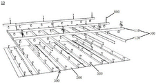
Fig. 1 is an exploded view of a fabricated ceiling structure provided by an embodiment of the present invention.
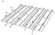
Fig. 2 is a schematic structural diagram of a fabricated ceiling structure according to an embodiment of the present invention.
Fig. 3 is an assembly schematic view of a fabricated ceiling structure provided by an embodiment of the present invention.
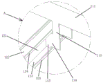
Fig. 4 is an enlarged view of a portion a in fig. 2.
Fig. 5 is an enlarged view at B in fig. 2.
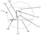
Fig. 6 is an enlarged view at C in fig. 3.
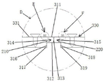
Fig. 7 is an enlarged view at D in fig. 3.
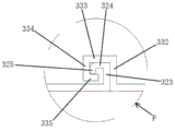
Fig. 8 is an enlarged view at E in fig. 7.
Fig. 9 is an enlarged view at F in fig. 7.
Detailed Description
The technical solutions in the present invention will be described clearly and completely with reference to the accompanying drawings, and it is obvious that the described embodiments are some, not all embodiments of the present invention. All other embodiments, which can be obtained by a person skilled in the art without any inventive step based on the embodiments of the present invention, shall fall within the scope of protection of the present invention.
As shown in fig. 1-3, embodiments of the present invention provide a fabricated ceiling structure 10 comprising: a keel assembly 100, a plurality of panels 200, and a plurality of splice assemblies 300.
The keel assembly 100 is fixed to the top wall 400 for lifting the panel 200.
The top surface of each panel 200 is fixedly connected with at least one row of hangers 500, the panels 200 are assembled into a whole through the splicing assembly 300 between two adjacent panels 200, any two adjacent panels 200 in the panels 200 are assembled and connected through the splicing assembly 300, and the at least one row of hangers 500 of each panel 200 can be hung on the keel assembly 100 by lifting the whole.
The fabricated ceiling structure 10 provided by the embodiment of the utility model is fixed on the top wall 400 through the keel assembly 100, the plurality of panels 200 are assembled into a whole through the splicing assembly 300, and then the whole is lifted up, so that at least one row of hanging pieces 500 of each panel 200 can be hung on the keel assembly 100, the plurality of panels 200 can be assembled on the ground, the operation is convenient, the flatness is adjusted, and then the plurality of panels 200 assembled into a whole are lifted up and hung on the keel assembly 100, so that the assembling operation is simple, the construction efficiency is high, and the flatness of the assembled panels is good.
As a preferred implementation manner of the embodiment of the present invention, as shown in fig. 5, 7, and 9, the splicing assembly 300 includes a splicing line 310 and two rows of clamping members 330, the splicing line 310 includes a first horizontal bar 311 and a second horizontal bar 312 that are disposed at an interval from top to bottom, the middle portions of the first horizontal bar 311 and the second horizontal bar 312 are connected by a first vertical bar 313, the first horizontal bar 311, the first vertical bar 313 and the second horizontal bar 312 enclose a first insertion groove 314 and a second insertion groove 315 that are located at two sides of the first vertical bar 313, the splicing line 310 further includes a second vertical bar 316, a third horizontal bar 317, a third vertical bar 318 and a fourth horizontal bar 319, the top end of the second vertical bar 316 is connected to one end of the second horizontal bar 312, the top end of the third vertical bar 318 is connected to the other end of the second horizontal bar 312, the third horizontal bar 317 is connected to the bottom end of the second vertical bar 316 and is located at a position far away from the second vertical bar 316 On one side of the third vertical bar 318, the fourth horizontal bar 319 is connected to the bottom end of the third vertical bar 318 and is located on one side of the third vertical bar 318 away from the second vertical bar 316, the adjacent ends of two adjacent panels 200 are respectively provided with a first protrusion 210 and a second protrusion 220, the first protrusion 210 and the second protrusion 220 are respectively matched and inserted into the first insertion groove 314 and the second insertion groove 315, the side surfaces of two adjacent panels 200 respectively located below the first protrusion 210 and the second protrusion 220 are respectively attached to the second vertical bar 316 and the third vertical bar 318, and the top surfaces of the third horizontal bar 317 and the fourth horizontal bar 319 are respectively attached to the bottom surfaces of two adjacent panels 200; the patchwork line 310 further comprises a fourth vertical bar 320, a fifth horizontal bar 321, a first hemmed bar 322, a fifth vertical bar 323, a sixth horizontal bar 324 and a second hemmed bar 325, wherein the bottom end of the fourth vertical bar 320 is connected with one end of the first horizontal bar 311, the top end of the fourth vertical bar 320 is connected with one end of the fifth horizontal bar 321, the other end of the fifth horizontal bar 321 is connected with the top end of the first hemmed bar 322, and the fifth horizontal bar 321, the first hemmed bar 322 and the first horizontal bar 311 are located on the same side of the fourth vertical bar 320; the bottom end of the fifth vertical bar 323 is connected to the other end of the first horizontal bar 311, the top end of the fifth vertical bar 323 is connected to one end of the sixth horizontal bar 324, the other end of the sixth horizontal bar 324 is connected to the top end of the second hemmer bar 325, and the sixth horizontal bar 324, the second hemmer bar 325 and the first horizontal bar 311 are located on the same side of the fifth vertical bar 323. The clamping member 330 comprises a horizontal plate 331, a first vertical section 332, a first horizontal section 333, a second vertical section 334 and a first crimping section 335, wherein the bottom end of the first vertical section 332 is connected with the outer end of the horizontal plate 331, the top end of the first vertical section 332 is connected with the inner end of the first horizontal section 333, the outer end of the first horizontal section 333 is connected with the top end of the second vertical section 334, and the bottom end of the second vertical section 334 is connected with the outer end of the first crimping section 335; the horizontal plates 331 of the two rows of clamping pieces 330 are respectively fixed on the top surfaces of the two adjacent end parts of the two panels 200, the fourth vertical bar 320, the fifth horizontal bar 321 and the first hemming bar 322 are clamped on the two adjacent panels, one row of the first hemming bar 322 is clamped on one panel of the two adjacent panels 200, the first vertical section 332, the first horizontal section 333, the second vertical section 334 and the first hemming bar 335 of the clamping pieces 330 are clamped between the fifth vertical bar 323, the sixth horizontal bar 324 and the second hemming bar 325, and the fifth vertical bar 323, the sixth horizontal bar 324 and the second hemming bar 325 are clamped between the first vertical section 332, the first horizontal section 333, the second vertical section 334 and the first hemming bar 335 of the other panel of the panel 200. In this embodiment, adjacent two in the polylith panel 200 assemble the connection through piece lines 310 and two rows of joint spare 330 between the panel 200, not only can assemble panel 200 subaerial, the holistic roughness of control panel of being convenient for can prevent moreover that panel 200 from causing because expend with heat and contract with cold and forming the uneven or gap grow scheduling problem of piece.
As a preferred embodiment of the present invention, as shown in fig. 4 to 6, the keel assembly 100 includes a plurality of main keels 110 and a plurality of cross keels 120, and each main keel 110 includes a main keel body 111 and a plurality of hooking bodies 112 spaced apart from each other at the bottom of the main keel body 111; the hanging body 112 comprises a third vertical section 113, a second horizontal section 114 and a fourth vertical section 115, the top end of the third vertical section 113 is connected with the bottom of the main keel body 111, the bottom end of the third vertical section 113 is connected with one end of the second horizontal section 114, the other end of the second horizontal section 114 is connected with one side of the fourth vertical section 115, the top end and the bottom end of the fourth vertical section 115 respectively protrude out of the second horizontal section 114, and a groove 116 is formed between the top end of the fourth vertical section 115 and the second horizontal section 114 as well as between the top end of the fourth vertical section 115 and the third vertical section 113; the false keel 120 comprises a sixth vertical bar 121, a seventh horizontal bar 122, an eighth horizontal bar 123, a third edge rolling bar 124 and a fourth edge rolling bar 125, wherein the top end of the sixth vertical bar 121 is connected with one end of the seventh horizontal bar 122, the bottom end of the sixth vertical bar 121 is connected with one end of the eighth horizontal bar 123, the other end of the seventh horizontal bar 122 is connected with the top end of the third edge rolling bar 124, and the other end of the eighth horizontal bar 123 is connected with the bottom end of the fourth edge rolling bar 125; the main keels 110 are arranged between the wall body 600 on one side and the wall body 700 on the other side at intervals, main keel bodies 111 of the main keels 110 are perpendicular to the wall body 600 on one side and the wall body 700 on the other side, and the main keel bodies 111 of the main keels 110 are fixed to the top wall 400 through expansion bolts 800; the multiple cross keels 120 are perpendicular to the main keel bodies 111 of the multiple main keels 110 and are respectively hung on the multiple rows of hanging bodies 112 opposite to the multiple main keels 110, the seventh horizontal bar 122 is supported at the top end of the fourth vertical section 115, the sixth vertical bar 121 is located on one side, away from the third vertical section 113, of the fourth vertical section 115, and the third edge rolling bar 124 is accommodated in the groove body 116. In this embodiment, the hooking body 112 of the main keel 110 and the cross runner 120 are connected by a clip, and the panel 200 is easy to assemble, easy to install, and reliable in connection.
As a preferred implementation manner of the embodiment of the present invention, as shown in fig. 5 and 6, the panel 200 is a stone-plastic plate or a wood-plastic plate, the top surface of the panel 200 is provided with at least one strip-shaped groove 230, the lower portions of the at least one row of hangers 500 are respectively embedded and fixed in the at least one strip-shaped groove 230, and the upper portions of the at least one row of hangers 500 are respectively hung on at least one of the furrows 120. In this embodiment, panel 200 need not to install additional structures such as section bar on panel 200 and prevents panel 200 and take place to warp after the installation through adopting the panel reinforcing intensity of stone plastic or wood plastic material, only needs to inlay at least one row of pendant 500 and establishes in at least one bar recess 230 of panel 200 top surface, just can hang the dress on false keel 120, can reduce the use of material, the assembly of being convenient for to can improve installation efficiency of construction.
As a preferred implementation manner of the embodiment of the present invention, as shown in fig. 5 and 6, the hanger 500 includes a third horizontal segment 510, a fifth vertical segment 520, a fourth horizontal segment 530 and a second curled segment 540, a bottom end of the fifth vertical segment 520 is connected to one end of the third horizontal segment 510, a top end of the fifth vertical segment 520 is connected to one end of the fourth horizontal segment 530, and a top end of the second curled segment 540 is connected to the other end of the fourth horizontal segment 530; the third horizontal segments 510 of at least one row of the hangers 500 are respectively embedded and fixed in the at least one bar-shaped groove 230; the fourth horizontal segments 530 of the at least one row of hangers 500 of the panels 200 are respectively supported on the seventh horizontal bar 122 of the at least one cross runner 120, and the second hemmed segment 540 is located on a side of the third hemmed bar 124 away from the sixth vertical bar 121, and the fifth vertical segment 520 is located on a side of the sixth vertical bar 121 away from the third hemmed bar 124. In this embodiment, the hanging member 500 includes a third horizontal segment 510, a fifth vertical segment 520, a fourth horizontal segment 530 and a second curled segment 540, the third horizontal segment 510 may be embedded in the strip-shaped groove 230 of the panel 200, the fifth vertical segment 520, the fourth horizontal segment 530 and the second curled segment 540 may be hung on the furring channel 120, and the hanging member 500 has a simple structure and is convenient to assemble with the panel 200 and the furring channel 120.
As a preferred embodiment of the present invention, the third horizontal segments 510 of at least one row of the hangers 500 are respectively adhered and fixed to the panel 200. In this embodiment, the hanging member 500 is simply fixed to the panel 200, and the efficiency of installation and construction can be further improved.
As a preferred embodiment of the present invention, as shown in fig. 5 and 6, the third horizontal segment 510, the fourth horizontal segment 530, and the second hemming segment 540 are respectively located at two sides of the fifth vertical segment 520. In this embodiment, the hanging member 500 is conveniently hung on the cross keel 120.
As a preferred implementation manner of the embodiment of the present invention, the hanging member 500 is a metal member or a plastic member. In this embodiment, the hanger 500 has a high strength, and the panel 200 can be stably hung on the cross runner 120.
As a preferred embodiment of the present invention, the bottom surface of the panel 200 is covered with a film. Specifically, the film is a composite film, a polyester film, a nylon film or a plastic film, and the film is bonded and fixed to the bottom surface of the panel 200. In this embodiment, the aesthetic appearance of the panel 200 can be enhanced.
An embodiment of the present invention further provides an installation method of an assembled ceiling structure, where the assembled ceiling structure is the assembled ceiling structure 10 described above, as shown in fig. 1 to 3, and the installation method includes the following steps:
laying out and positioning the top wall 400, and fixing the keel assembly 100 on the top wall 400;
assembling the panels 200 into a whole by a plurality of the splicing assemblies 300, and lifting the whole to hang the at least one row of hanging pieces 500 of each panel 200 on the keel assembly 100.
The fabricated ceiling structure 10 provided by the embodiment of the utility model is fixed on the top wall 400 through the keel assembly 100, the plurality of panels 200 are assembled into a whole through the splicing assembly 300, and then the whole is lifted up, so that at least one row of hanging pieces 500 of each panel 200 can be hung on the keel assembly 100, the plurality of panels 200 can be assembled on the ground, the operation is convenient, the flatness is adjusted, and then the plurality of panels 200 assembled into a whole are lifted up and hung on the keel assembly 100, so that the assembling operation is simple, the construction efficiency is high, and the flatness of the assembled panels is good.
While the utility model has been described with reference to specific embodiments, the utility model is not limited thereto, and various equivalent modifications and substitutions can be easily made by those skilled in the art within the technical scope of the utility model. Therefore, the protection scope of the present invention shall be subject to the protection scope of the claims.
Claims (9)
1. An assembled ceiling structure, comprising: the keel assembly comprises a keel assembly, a plurality of panels and a plurality of splicing assemblies; the keel assembly is fixed on the top wall; the top surface of each panel is fixedly connected with at least one row of hanging pieces, the panels are assembled into a whole through a splicing assembly between two adjacent panels, and the whole is lifted up, so that the at least one row of hanging pieces of each panel is hung on the keel assembly.
2. The fabricated ceiling structure of claim 1, wherein the splicing assembly comprises a splicing line and two rows of clamping members, the splicing line comprises a first horizontal bar and a second horizontal bar which are arranged at intervals up and down, the middle parts of the first horizontal bar and the second horizontal bar are connected through the first vertical bar, the first horizontal bar, the first vertical bar and the second horizontal bar enclose a first inserting groove and a second inserting groove which are positioned at two sides of the first vertical bar, the splicing line further comprises a second vertical bar, a third horizontal bar, a third vertical bar and a fourth horizontal bar, the top end of the second vertical bar is connected with one end of the second horizontal bar, the top end of the third vertical bar is connected with the other end of the second horizontal bar, the third horizontal bar is connected with the bottom end of the second vertical bar and is positioned at one side of the second vertical bar far away from the third vertical bar, the fourth horizontal bar is connected with the bottom end of the third vertical bar and is positioned on one side of the third vertical bar, which is far away from the second vertical bar, the adjacent end parts of two adjacent panels are respectively provided with a first protruding part and a second protruding part, the first protruding part and the second protruding part are respectively matched and inserted in the first inserting groove and the second inserting groove, the side surfaces of two adjacent panels, which are respectively positioned below the first protruding part and the second protruding part, are respectively attached to the second vertical bar and the third vertical bar, and the top surface of the third horizontal bar and the top surface of the fourth horizontal bar are respectively attached to the bottom surfaces of two adjacent panels; the splicing line further comprises a fourth vertical bar, a fifth horizontal bar, a first hemming bar, a fifth vertical bar, a sixth horizontal bar and a second hemming bar, wherein the bottom end of the fourth vertical bar is connected with one end of the first horizontal bar, the top end of the fourth vertical bar is connected with one end of the fifth horizontal bar, the other end of the fifth horizontal bar is connected with the top end of the first hemming bar, and the fifth horizontal bar, the first hemming bar and the first horizontal bar are positioned on the same side of the fourth vertical bar; the bottom end of the fifth vertical bar is connected with the other end of the first horizontal bar, the top end of the fifth vertical bar is connected with one end of the sixth horizontal bar, the other end of the sixth horizontal bar is connected with the top end of the second edge rolling bar, and the sixth horizontal bar, the second edge rolling bar and the first horizontal bar are positioned on the same side of the fifth vertical bar; the clamping piece comprises a horizontal plate, a first vertical section, a first horizontal section, a second vertical section and a first crimping section, wherein the bottom end of the first vertical section is connected with the outer end of the horizontal plate, the top end of the first vertical section is connected with the inner end of the first horizontal section, the outer end of the first horizontal section is connected with the top end of the second vertical section, and the bottom end of the second vertical section is connected with the outer end of the first crimping section; the horizontal plates of the two rows of clamping pieces are respectively fixed at two adjacent top surfaces of the two adjacent end parts of the panel, the fourth vertical strip, the fifth horizontal strip and the first curling strip are clamped at two adjacent panels, one row of the panel is arranged in the panel, the clamping pieces are arranged between the first vertical section, the first horizontal section, the second vertical section and the first curling strip, the fifth vertical strip, the sixth horizontal strip and the second curling strip are clamped at two adjacent panels, the other row of the panel is arranged on the other panel, and the clamping pieces are arranged between the first vertical section, the first horizontal section, the second vertical section and the first curling strip.
3. The fabricated ceiling structure of claim 2, wherein the runner assembly includes a plurality of main runners and a plurality of cross runners, the main runners including a main runner body and a plurality of hitching bodies spaced apart at a bottom of the main runner body; the hanging body comprises a third vertical section, a second horizontal section and a fourth vertical section, the top end of the third vertical section is connected with the bottom of the main keel body, the bottom end of the third vertical section is connected with one end of the second horizontal section, the other end of the second horizontal section is connected with one side of the fourth vertical section, the top end and the bottom end of the fourth vertical section respectively protrude out of the second horizontal section, and a groove body is formed between the top end of the fourth vertical section and the second horizontal section as well as between the top end of the fourth vertical section and the third vertical section; the auxiliary keel comprises a sixth vertical strip, a seventh horizontal strip, an eighth horizontal strip, a third edge rolling strip and a fourth edge rolling strip, the top end of the sixth vertical strip is connected with one end of the seventh horizontal strip, the bottom end of the sixth vertical strip is connected with one end of the eighth horizontal strip, the other end of the seventh horizontal strip is connected with the top end of the third edge rolling strip, and the other end of the eighth horizontal strip is connected with the bottom end of the fourth edge rolling strip; the main keels are arranged between the wall body on one side and the wall body on the other side at intervals, main keel bodies of the main keels are perpendicular to the wall body on one side and the wall body on the other side, and the main keel bodies of the main keels are fixed on the top wall through expansion bolts; many false keels with the main joist body of many main joists is perpendicular and articulate respectively on many main joist just right multirow articulates the body, seventh horizontal bar support in the top of fourth vertical section, sixth vertical is located fourth vertical section is kept away from one side of third vertical section, third turn-up strip hold in the cell body.
4. The fabricated ceiling structure of claim 3, wherein the panel is a stone-plastic plate or a wood-plastic plate, the top surface of the panel is provided with at least one strip-shaped groove, the lower parts of the at least one row of hanging pieces are respectively embedded and fixed in the at least one strip-shaped groove, and the upper parts of the at least one row of hanging pieces are respectively hung on at least one auxiliary keel.
5. The fabricated ceiling structure of claim 4, wherein the hanging member comprises a third horizontal section, a fifth vertical section, a fourth horizontal section, and a second curled section, wherein a bottom end of the fifth vertical section is connected to one end of the third horizontal section, a top end of the fifth vertical section is connected to one end of the fourth horizontal section, and a top end of the second curled section is connected to the other end of the fourth horizontal section; the third horizontal sections of the at least one row of the hanging pieces are respectively embedded and fixed in the at least one strip-shaped groove; the fourth horizontal sections of the at least one row of hangers of the plurality of panels are respectively supported on a seventh horizontal bar of the at least one cross runner, the second hemming section is located on one side of the third hemming bar away from the sixth vertical bar, and the fifth vertical section is located on one side of the sixth vertical bar away from the third hemming bar.
6. The fabricated ceiling structure of claim 5, wherein the third horizontal segments of at least one row of hangers are respectively adhesively secured to the panels.
7. The fabricated ceiling structure of claim 6, wherein the third horizontal segment and the fourth horizontal segment and second bead segment are located on either side of the fifth vertical segment.
8. The fabricated ceiling structure of claim 7, wherein the hanging member is a metal or plastic member.
9. The fabricated ceiling structure of claim 8, wherein the bottom surface of the panel is covered and adhesively secured with a film.
Priority Applications (1)
| Application Number | Priority Date | Filing Date | Title |
|---|---|---|---|
| CN202121323969.4U CN215829759U (en) | 2021-06-15 | 2021-06-15 | Assembled furred ceiling structure |
Applications Claiming Priority (1)
| Application Number | Priority Date | Filing Date | Title |
|---|---|---|---|
| CN202121323969.4U CN215829759U (en) | 2021-06-15 | 2021-06-15 | Assembled furred ceiling structure |
Publications (1)
| Publication Number | Publication Date |
|---|---|
| CN215829759U true CN215829759U (en) | 2022-02-15 |
Family
ID=80190134
Family Applications (1)
| Application Number | Title | Priority Date | Filing Date |
|---|---|---|---|
| CN202121323969.4U Active CN215829759U (en) | 2021-06-15 | 2021-06-15 | Assembled furred ceiling structure |
Country Status (1)
| Country | Link |
|---|---|
| CN (1) | CN215829759U (en) |
-
2021
- 2021-06-15 CN CN202121323969.4U patent/CN215829759U/en active Active
Similar Documents
| Publication | Publication Date | Title |
|---|---|---|
| CN201486077U (en) | Suspended ceiling structure | |
| CN113293913A (en) | Assembly type ceiling structure and installation method | |
| CN111188437A (en) | Assembled and movable metal keel partition wall system | |
| CN215829759U (en) | Assembled furred ceiling structure | |
| CN215829756U (en) | Suspended ceiling curtain box structure | |
| CN113293912A (en) | Edge folding structure of assembled suspended ceiling and installation method | |
| CN217128688U (en) | Assembled furred ceiling with rearmounted bearing structure | |
| CN214614941U (en) | Assembled suspended ceiling structure without suspender | |
| CN114197726A (en) | Hook-up type assembled ceiling and installation method | |
| CN214614961U (en) | General embedded decorative board mosaic structure of furred ceiling | |
| CN215829757U (en) | House grade drop furred ceiling | |
| CN217128699U (en) | Stable splicing structure of panel | |
| CN113293914A (en) | Assembly type ceiling with rear bearing structure and mounting method | |
| CN213741851U (en) | Modularization ceiling system | |
| CN113417397A (en) | Suspended ceiling curtain box structure and installation method | |
| CN209891542U (en) | Assembled wall installation component and wall | |
| CN113293918A (en) | Panel stable splicing structure and installation method | |
| CN215829760U (en) | Assembled furred ceiling with light trough structure | |
| CN215888902U (en) | Ceiling plate with embedded hanging pieces | |
| CN215829761U (en) | Edge folding structure of assembled suspended ceiling | |
| CN113338517A (en) | Residential grade-falling ceiling and installation method | |
| CN110821098A (en) | Buckle mounting, decoration material and decoration material fixed component | |
| KR200452845Y1 (en) | Ridge ornament of metals roof | |
| CN113293915A (en) | Assembly type ceiling with light trough structure and installation method | |
| CN217128687U (en) | Cascade connection structure |
Legal Events
| Date | Code | Title | Description |
|---|---|---|---|
| GR01 | Patent grant | ||
| GR01 | Patent grant |