CN113175715A - Control method and related device for evaporative cooling and waste heat recovery unit of data center - Google Patents
Control method and related device for evaporative cooling and waste heat recovery unit of data center Download PDFInfo
- Publication number
- CN113175715A CN113175715A CN202110481470.4A CN202110481470A CN113175715A CN 113175715 A CN113175715 A CN 113175715A CN 202110481470 A CN202110481470 A CN 202110481470A CN 113175715 A CN113175715 A CN 113175715A
- Authority
- CN
- China
- Prior art keywords
- air
- cooling
- valve
- heat
- recovery unit
- Prior art date
- Legal status (The legal status is an assumption and is not a legal conclusion. Google has not performed a legal analysis and makes no representation as to the accuracy of the status listed.)
- Granted
Links
Images


Classifications
-
- F—MECHANICAL ENGINEERING; LIGHTING; HEATING; WEAPONS; BLASTING
- F24—HEATING; RANGES; VENTILATING
- F24F—AIR-CONDITIONING; AIR-HUMIDIFICATION; VENTILATION; USE OF AIR CURRENTS FOR SCREENING
- F24F5/00—Air-conditioning systems or apparatus not covered by F24F1/00 or F24F3/00, e.g. using solar heat or combined with household units such as an oven or water heater
- F24F5/0007—Air-conditioning systems or apparatus not covered by F24F1/00 or F24F3/00, e.g. using solar heat or combined with household units such as an oven or water heater cooling apparatus specially adapted for use in air-conditioning
- F24F5/001—Compression cycle type
-
- F—MECHANICAL ENGINEERING; LIGHTING; HEATING; WEAPONS; BLASTING
- F24—HEATING; RANGES; VENTILATING
- F24F—AIR-CONDITIONING; AIR-HUMIDIFICATION; VENTILATION; USE OF AIR CURRENTS FOR SCREENING
- F24F11/00—Control or safety arrangements
- F24F11/62—Control or safety arrangements characterised by the type of control or by internal processing, e.g. using fuzzy logic, adaptive control or estimation of values
- F24F11/63—Electronic processing
- F24F11/64—Electronic processing using pre-stored data
-
- F—MECHANICAL ENGINEERING; LIGHTING; HEATING; WEAPONS; BLASTING
- F24—HEATING; RANGES; VENTILATING
- F24F—AIR-CONDITIONING; AIR-HUMIDIFICATION; VENTILATION; USE OF AIR CURRENTS FOR SCREENING
- F24F11/00—Control or safety arrangements
- F24F11/62—Control or safety arrangements characterised by the type of control or by internal processing, e.g. using fuzzy logic, adaptive control or estimation of values
- F24F11/63—Electronic processing
- F24F11/65—Electronic processing for selecting an operating mode
-
- F—MECHANICAL ENGINEERING; LIGHTING; HEATING; WEAPONS; BLASTING
- F24—HEATING; RANGES; VENTILATING
- F24F—AIR-CONDITIONING; AIR-HUMIDIFICATION; VENTILATION; USE OF AIR CURRENTS FOR SCREENING
- F24F12/00—Use of energy recovery systems in air conditioning, ventilation or screening
-
- F—MECHANICAL ENGINEERING; LIGHTING; HEATING; WEAPONS; BLASTING
- F24—HEATING; RANGES; VENTILATING
- F24F—AIR-CONDITIONING; AIR-HUMIDIFICATION; VENTILATION; USE OF AIR CURRENTS FOR SCREENING
- F24F13/00—Details common to, or for air-conditioning, air-humidification, ventilation or use of air currents for screening
- F24F13/22—Means for preventing condensation or evacuating condensate
-
- F—MECHANICAL ENGINEERING; LIGHTING; HEATING; WEAPONS; BLASTING
- F24—HEATING; RANGES; VENTILATING
- F24F—AIR-CONDITIONING; AIR-HUMIDIFICATION; VENTILATION; USE OF AIR CURRENTS FOR SCREENING
- F24F13/00—Details common to, or for air-conditioning, air-humidification, ventilation or use of air currents for screening
- F24F13/30—Arrangement or mounting of heat-exchangers
-
- F—MECHANICAL ENGINEERING; LIGHTING; HEATING; WEAPONS; BLASTING
- F24—HEATING; RANGES; VENTILATING
- F24F—AIR-CONDITIONING; AIR-HUMIDIFICATION; VENTILATION; USE OF AIR CURRENTS FOR SCREENING
- F24F5/00—Air-conditioning systems or apparatus not covered by F24F1/00 or F24F3/00, e.g. using solar heat or combined with household units such as an oven or water heater
- F24F5/0007—Air-conditioning systems or apparatus not covered by F24F1/00 or F24F3/00, e.g. using solar heat or combined with household units such as an oven or water heater cooling apparatus specially adapted for use in air-conditioning
- F24F5/0035—Air-conditioning systems or apparatus not covered by F24F1/00 or F24F3/00, e.g. using solar heat or combined with household units such as an oven or water heater cooling apparatus specially adapted for use in air-conditioning using evaporation
-
- F—MECHANICAL ENGINEERING; LIGHTING; HEATING; WEAPONS; BLASTING
- F24—HEATING; RANGES; VENTILATING
- F24F—AIR-CONDITIONING; AIR-HUMIDIFICATION; VENTILATION; USE OF AIR CURRENTS FOR SCREENING
- F24F7/00—Ventilation
- F24F7/04—Ventilation with ducting systems, e.g. by double walls; with natural circulation
- F24F7/06—Ventilation with ducting systems, e.g. by double walls; with natural circulation with forced air circulation, e.g. by fan positioning of a ventilator in or against a conduit
- F24F7/08—Ventilation with ducting systems, e.g. by double walls; with natural circulation with forced air circulation, e.g. by fan positioning of a ventilator in or against a conduit with separate ducts for supplied and exhausted air with provisions for reversal of the input and output systems
-
- F—MECHANICAL ENGINEERING; LIGHTING; HEATING; WEAPONS; BLASTING
- F24—HEATING; RANGES; VENTILATING
- F24F—AIR-CONDITIONING; AIR-HUMIDIFICATION; VENTILATION; USE OF AIR CURRENTS FOR SCREENING
- F24F13/00—Details common to, or for air-conditioning, air-humidification, ventilation or use of air currents for screening
- F24F13/22—Means for preventing condensation or evacuating condensate
- F24F2013/221—Means for preventing condensation or evacuating condensate to avoid the formation of condensate, e.g. dew
-
- F—MECHANICAL ENGINEERING; LIGHTING; HEATING; WEAPONS; BLASTING
- F24—HEATING; RANGES; VENTILATING
- F24F—AIR-CONDITIONING; AIR-HUMIDIFICATION; VENTILATION; USE OF AIR CURRENTS FOR SCREENING
- F24F2110/00—Control inputs relating to air properties
- F24F2110/10—Temperature
- F24F2110/12—Temperature of the outside air
-
- Y—GENERAL TAGGING OF NEW TECHNOLOGICAL DEVELOPMENTS; GENERAL TAGGING OF CROSS-SECTIONAL TECHNOLOGIES SPANNING OVER SEVERAL SECTIONS OF THE IPC; TECHNICAL SUBJECTS COVERED BY FORMER USPC CROSS-REFERENCE ART COLLECTIONS [XRACs] AND DIGESTS
- Y02—TECHNOLOGIES OR APPLICATIONS FOR MITIGATION OR ADAPTATION AGAINST CLIMATE CHANGE
- Y02B—CLIMATE CHANGE MITIGATION TECHNOLOGIES RELATED TO BUILDINGS, e.g. HOUSING, HOUSE APPLIANCES OR RELATED END-USER APPLICATIONS
- Y02B30/00—Energy efficient heating, ventilation or air conditioning [HVAC]
- Y02B30/56—Heat recovery units
Landscapes
- Engineering & Computer Science (AREA)
- Chemical & Material Sciences (AREA)
- Combustion & Propulsion (AREA)
- Mechanical Engineering (AREA)
- General Engineering & Computer Science (AREA)
- Signal Processing (AREA)
- Physics & Mathematics (AREA)
- Fuzzy Systems (AREA)
- Mathematical Physics (AREA)
- Life Sciences & Earth Sciences (AREA)
- Sustainable Development (AREA)
- Air Conditioning Control Device (AREA)
Abstract
The invention provides a control method and a related device for a data center evaporative cooling and waste heat recovery unit, which belong to the technical field of air conditioners, wherein the data center evaporative cooling and waste heat recovery unit can be used for cooling a machine room and comprises the following steps: cooling system, cooling system includes: the air duct is communicated with the machine room; the cooling device is arranged on the air inlet side of the air duct and can be used for cooling the machine room; a compression system, the compression system comprising: a compressor; the first heat exchange device is communicated with the compressor; the second heat exchange device is communicated with the first heat exchange device and the compressor, is positioned in the air duct and can absorb heat from the air duct; the heat exchange pipeline is provided with a water supply port and a water return port which are communicated, and the first heat exchange device can be used for supplying heat to the heat exchange pipeline. The invention realizes the high-efficiency mechanical cold compensation and waste heat recovery of the data center machine room, and also has the advantages of modularization and engineering removal.
Description
Technical Field
The invention relates to the technical field of air conditioners, in particular to a control method and a related device for a data center evaporative cooling and waste heat recovery unit.
Background
The cooling energy consumption of a machine room of the data center is high and accounts for about 30% of the total energy consumption of the data center, the evaporative cooling can be realized by refrigerating by using dry air energy, and the evaporative cooling air treatment technology is widely applied in the industry. The data center runs all the year round, continuously generates a large amount of heat, and waste heat resources are very abundant, but most data center evaporative cooling air handling units in the industry at present do not have the waste heat recovery function, and a few schemes with the waste heat recovery function need to be added with a waste heat recovery heat exchanger and a matched heat pump system, so that the heat pump system has many pipelines and is complex in construction, the original advantages of modularization and engineering removal of the evaporative cooling air handling units are greatly weakened, the engineering quantity of field construction is very high, and the comprehensive economic benefit is not good.
Disclosure of Invention
The invention aims to at least solve the technical problems that in the prior art, a data center evaporative cooling and waste heat recovery unit has a plurality of pipelines, is complex and modularized in construction and has low engineering removal degree.
To this end, the invention provides, in a first aspect, a data center evaporative cooling and waste heat recovery unit.
The invention provides a control method of a data center evaporative cooling and waste heat recovery unit.
The invention provides a control device of a data center evaporative cooling and waste heat recovery unit.
A fourth aspect of the invention provides a readable storage medium.
The invention provides a data center evaporative cooling and waste heat recovery unit, which can be used for cooling a machine room, and comprises: cooling system, cooling system includes: the air duct is communicated with the machine room; the cooling device is arranged on the air inlet side of the air duct and can be used for cooling the machine room; a compression system, the compression system comprising: a compressor; the first heat exchange device is communicated with the compressor; the second heat exchange device is communicated with the first heat exchange device and the compressor, is positioned in the air duct and can absorb heat from the air duct; the heat exchange pipeline is provided with a water supply port and a water return port which are communicated, and the first heat exchange device can be used for supplying heat to the heat exchange pipeline.
The data center evaporative cooling and waste heat recovery unit provided by the invention can be used for cooling a machine room so as to ensure the proper temperature in the machine room and ensure the storage and use safety of electrical equipment in the machine room. The data center evaporative cooling and waste heat recovery unit comprises a cooling system and a compression system which are matched with each other. Wherein, cooling system includes wind channel and heat sink. The air duct is provided with an air inlet side and an air outlet side which are communicated, and outdoor fresh air can enter the machine room from the air inlet side so as to cool the environment in the machine room; the air after heat exchange can be discharged out of the machine room from the air outlet side, and the whole air flow is ensured. The cooling device is arranged on the air inlet side of the air duct and can contact with air flow on the air inlet side to exchange heat in the operation process so as to reduce the temperature of air entering the machine room and further improve the cooling effect on the machine room.
In addition, the compression system comprises a compressor, a first heat exchange device, a second heat exchange device and a heat exchange pipeline which are matched for use. The first heat exchange device is communicated with the compressor and can be arranged inside the air duct or outside the air duct; the second heat exchange device is communicated with the first heat exchange device and the compressor and is arranged in the air duct; the heat exchange pipeline is provided with a water supply port and a water return port which are communicated, and the heat exchange pipeline is in contact with the first heat exchange device and can be in contact with the first heat exchange device for heat exchange, so that heat transfer is realized.
Specifically, when the compression system works, the compressor operates to enable the second heat exchange device to absorb heat from the air duct, so that the second heat exchange device can play a role in refrigerating on the air inlet side of the air duct and can release heat on the air outlet side of the air duct; in outside water source accessible return water mouth enters into the heat transfer pipeline, water can contact the heat transfer with first heat transfer device when flowing through first heat transfer device, then flow out the heat transfer pipeline through the supply port, the water after obtaining the heat transfer supplies with hot user, realize thermal collection, in order to reach energy saving and emission reduction's purpose, make data center evaporative cooling and waste heat recovery unit both possess the advantage that conventional evaporative cooling unit natural cooling efficiency is high, again can make full use of data center return air waste heat, can also keep data center evaporative cooling and waste heat recovery unit modularization, go the advantage of engineering.
In addition, the second heat exchange device can also discharge heat at the air outlet side of the air duct, at the moment, the second heat exchange part of the second heat exchange device is used as a condenser of the compression system, and the first heat exchange device does not work.
In addition, the second heat exchange device can also recover heat while discharging heat at the air outlet side of the air duct, and supply the heat to a heat user, and at the moment, the second heat exchange part of the second heat exchange device and the first heat exchange device are both used as a condenser of the refrigeration system.
According to the data center evaporative cooling and waste heat recovery unit, the cooling system and the compression system are organically combined, so that the conventional data center evaporative cooling and waste heat recovery unit has additional functions of waste heat recovery, mechanical cold supplement and the like, and efficient mechanical cold supplement and waste heat recovery of a data center machine room are realized on the premise of ensuring high energy efficiency evaporative cooling.
According to the data center evaporative cooling and waste heat recovery unit of the technical scheme, the data center evaporative cooling and waste heat recovery unit can also have the following additional technical characteristics:
in the above technical solution, the air duct includes: the air inlet channel is communicated with the machine room, and the cooling device is positioned in the air inlet channel; and the air exhaust channel is communicated with the machine room, and the first heat exchange device is arranged in the air exhaust channel.
In the technical scheme, the air duct comprises an air inlet channel and an air exhaust channel which are communicated. Wherein, the inlet end of the air inlet channel is communicated with the outdoor environment, the outlet end of the air inlet channel is communicated with the machine room, and the cooling device is arranged in the air inlet channel; when outdoor new trend enters into the computer lab from inlet air channel, can contact with the heat sink at first, if the heat sink is in the running state can carry out the heat transfer with the air current, if the heat sink stop work, can be directly through utilizing the outside air to cool down for the computer lab.
In addition, the air return opening of the exhaust channel is communicated with the machine room, low-temperature air is changed into hot air after heat exchange in the machine room, and the hot air can be exhausted through the exhaust channel or enter the air inlet channel again for recycling. The first heat exchange device is arranged in the exhaust channel and then contacts with hot air for heat exchange, so that the heat in the machine room is recovered, the collected heat is supplied to a heat user, and the purposes of energy conservation and emission reduction are achieved.
In particular, the return of hot air from the exhaust air channel to the intake air channel occurs in several cases:
the first condition is as follows: the outside air temperature is too low, and the outside air is directly sent into the computer lab through inlet air channel and can cause the condensation in the computer lab this moment. Therefore, part of hot air is introduced into the air inlet channel from the air exhaust channel, so that the external low-temperature cold air is mixed with the hot air in the air channel firstly and then is sent into the machine room. At this time, only part of the hot air intake duct is introduced from the exhaust duct.
Case two: the hot air returns to the air inlet channel from the air exhaust channel, and the heat of the machine room is recovered and sent to the hot users. At this time, the first heat exchanging part of the second heat exchanging device and the first heat exchanging device are both used as evaporators of the compression system (the first heat exchanging part and the first heat exchanging device can be simultaneously started or only one of the first heat exchanging device can be started), and the first heat exchanging device is used as a condenser of the compression system.
In any one of the above technical solutions, the second heat exchange device includes: the first heat exchanging part is arranged in the air inlet channel and communicated with the first heat exchanging device and the compressor.
In this technical scheme, second heat transfer device includes first heat transfer portion. Wherein, first heat transfer portion sets up in inlet air channel to be linked together with first heat transfer device and compressor. When the compression system is in an operating state, the first heat exchange part is matched with the first heat exchange device for use, the first heat exchange part can be used as an evaporator, and the first heat exchange device can be used as a condenser.
Therefore, based on the matching of the first heat exchanging part and the first heat exchanging device, the air in the air inlet channel is cooled through the first heat exchanging part, so that the effect of cooling the machine room is achieved; the heat in the machine room is collected through the first heat exchange device, and meanwhile, the heat generated by the compression system is collected, so that the collected heat is supplied to a heat user, and the purposes of energy conservation and emission reduction are achieved.
In any one of the above technical solutions, the second heat exchange device includes: the second heat exchanging part is arranged in the exhaust channel and communicated with the first heat exchanging device and the compressor.
In this technical scheme, second heat transfer device includes second heat transfer portion. The second heat exchange part is arranged in the exhaust channel and communicated with the first heat exchange device and the compressor. When the compression system is in an operating state, the second heat exchange part is matched with the first heat exchange device for use, the second heat exchange part can be used as an evaporator, and the first heat exchange device can be used as a condenser.
Therefore, based on the matching of the first heat exchange part and the first heat exchange device, the heat in the exhaust channel can be absorbed by the second heat exchange part and transferred to the first heat exchange device, and the first heat exchange device can be used as a condenser to supply the part of heat to a heat user, so that the purposes of energy conservation and emission reduction are achieved.
In any one of the above technical solutions, the second heat exchange device includes: the first heat exchanging part is arranged in the air inlet channel and communicated with the compressor; the second heat exchanging part is arranged in the exhaust channel and communicated with the first heat exchanging part and the first heat exchanging device and the compressor.
In the technical scheme, the second heat exchange device comprises a first heat exchange part and a second heat exchange part which are matched with each other. Wherein, first heat transfer portion and second heat transfer portion all can use with first heat transfer device cooperation to one or both in first heat transfer portion and the second heat transfer portion can regard as the evaporimeter to use, with absorb the heat at inlet air channel or exhaust air channel, realize the cooling to the computer lab or realize the thermal recovery to the computer lab.
Specifically, when first heat transfer portion and first heat transfer device cooperation were used, can absorb inlet air channel's heat based on first heat transfer portion to reduce the temperature in the computer lab, can collect the heat in the passageway of airing exhaust based on first heat transfer device, and collect compression system self heat, in order to supply this part heat to hot user.
Specifically, when the second heat exchanging portion is used in cooperation with the first heat exchanging device, the heat of the exhaust passage can be absorbed based on the second heat exchanging portion, and the heat of the compression system can be collected based on the first heat exchanging device, so that the part of the heat can be supplied to a heat user.
Specifically, when first heat transfer portion and second heat transfer portion used with first heat transfer device cooperation jointly, can absorb the heat of inlet air duct based on first heat transfer portion, absorb the heat of airing exhaust passageway based on second heat transfer portion, can collect the heat of compression system self based on first heat transfer device to supply this part of heat to the heat consumer.
From the outside, when first heat transfer portion and second heat transfer portion use with first heat transfer device cooperation jointly, still can regard as the evaporimeter with first heat transfer portion, second heat transfer portion and first heat transfer device all regard as the condenser.
In any of the above technical solutions, the compression system further includes: a first expansion valve disposed between the first heat exchanging part and the second heat exchanging part; a second expansion valve disposed between the first expansion valve and the second heat exchange portion; one end of the first heat exchange device is communicated with one end of the compressor communicated with the reversing valve, and the other end of the first heat exchange device is communicated between the first expansion valve and the second expansion valve through the third expansion valve; and the reversing valve is arranged between the first heat exchange device and the compressor.
In the technical scheme, the compression system further comprises a reversing component so as to realize the switching of the compression system under different working modes. Specifically, the reversing assembly includes a first expansion valve, a second expansion valve, a third expansion valve, and a reversing valve. The first expansion valve and the second expansion valve are arranged on a flow path between the first heat exchange part and the second heat exchange part at intervals, the first heat exchange part is arranged close to the second heat exchange part, and the second heat exchange part is arranged close to the first heat exchange part; the first heat exchange part is directly communicated with the compressor, and the second heat exchange part is communicated with the compressor through a reversing valve; one end of the first heat exchange device is communicated to a flow path between the first expansion valve and the second expansion valve through the third expansion valve, and the other end of the first heat exchange device is communicated between the reversing valve and the compressor.
Particularly, based on the cooperation of the first expansion valve, the second expansion valve, the third expansion valve and the reversing valve, the compression system can be switched under different operation modes.
In a specific embodiment, the compressor, the first heat exchanging part, the second heat exchanging part, the first expansion valve, the second expansion valve, and the third expansion valve of the compression system are all closed. At this time, the first heat exchange part is used as an evaporator, and the second heat exchange part is used as a condenser.
In a specific embodiment, the compressor, the first expansion valve and the third expansion valve are opened, the second expansion valve is fully closed, the reversing valve is reversed, the second heat exchange part serves as an evaporator, and the first heat exchange device serves as a condenser.
In a specific embodiment, the compressor, the first expansion valve, the second expansion valve and the third expansion valve are opened, the reversing valve is reversed, the first heat exchanging part and the second heat exchanging part are both used as evaporators, and the first heat exchanging device is used as a condenser.
In any one of the above technical schemes, the air inlet channel comprises an air inlet valve and an air supply outlet, and the air supply outlet is communicated with the machine room.
In the technical scheme, the air inlet channel is provided with an air inlet and an air supply outlet which are communicated, an air inlet valve is arranged at the position of the air inlet and communicated with the outdoor environment, the air supply outlet is communicated with the inside of the machine room, the cooling device and the first heat exchange part of the second heat exchange device are arranged between the air inlet and the air supply outlet, and outside fresh air can enter the machine room through the air inlet channel.
In any of the above technical solutions, the exhaust channel includes an air return opening and an exhaust valve which are communicated, and the air return opening is communicated with the machine room.
In the technical scheme, the exhaust channel is provided with an air return inlet and an air outlet which are communicated, the air return inlet is communicated with the machine room, the air outlet is provided with an exhaust valve, and the exhaust valve is communicated with the outdoor environment; when the exhaust valve is in an open state, air in the machine room can enter the air return channel through the air return opening and is exhausted from the exhaust opening.
In any of the above technical solutions, the data center evaporative cooling and waste heat recovery unit further includes an air mixing valve, and the air mixing valve is communicated with the air inlet channel and the air exhaust channel.
In the technical scheme, the data center evaporative cooling and waste heat recovery unit further comprises an air mixing valve. The air mixing valve is communicated with the air inlet channel and the air exhaust channel and can conduct the air inlet channel and the air exhaust channel or disconnect the air inlet channel and the air exhaust channel.
In the use, when the blast valve is in the closed condition, the gas that enters into in the exhaust passage can be discharged through the air exit, and the new trend of outdoor environment constantly enters into the computer lab through inlet air channel like this, and rethread exhaust passage is outdoor after the heat transfer with the computer lab. When the air mixing valve is in an open state, the air entering the exhaust channel can enter the air inlet channel again through the air mixing valve, so that the partial air flow participates in heat exchange and temperature reduction again.
In any of the above technical solutions, the cooling system further includes: and the first air valve is positioned between the air return opening and the first heat exchange device and communicated with the air exhaust channel.
In this technical scheme, cooling system still includes first blast gate. The first air valve is arranged between the air return opening and the first heat exchange device and communicated with the air exhaust channel. Therefore, in the using process, when the first air valve is in a closed state, the air entering the air exhaust channel can pass through the second heat exchange part of the second heat exchange device and then is exhausted outdoors through the air exhaust valve. When the first air valve is in an open state, the air entering the air exhaust channel can be directly exhausted from the first air valve without passing through the second heat exchange part of the second heat exchange device, or a part of the air is exhausted through the first air valve and a part of the air is exhausted through the exhaust valve.
In any of the above technical solutions, the cooling system further includes: the second air valve is arranged in the air exhaust channel and is positioned between the first air valve and the air exhaust valve; and the third air valve is positioned between the first heat exchange device and the exhaust valve and communicated with the exhaust channel.
In this technical scheme, cooling system still includes second blast gate and third blast gate. The second air valve is arranged in the air exhaust channel and positioned between the first air valve and the air exhaust valve, and the second air valve can be used for plugging part of the air exhaust channel between the first air valve and the air exhaust valve; the third air valve is arranged between the second heat exchanging part of the second heat exchanging device and the air exhaust valve and communicated with the air exhaust channel, and can guide the air flow in the air exhaust channel out of the room.
Thus, in use, when the second air valve is in a closed state, air in the machine room can directly exhaust airflow through the first air valve. The air exhaust channel is communicated with the outdoor environment through an air exhaust outlet and is communicated with the outdoor environment through a third air valve.
At this time, under the condition that the machine room needs mechanical cooling compensation but does not need waste heat recovery, one of the air outlet and the third air valve can be directly used as the air inlet, and the other one of the air outlet and the third air valve can be used as the air outlet (depending on the installation direction of the second fan). Therefore, the ambient air with lower outdoor temperature can be directly led into the position of the exhaust channel provided with the second heat exchanging part, so that the part of cold air is contacted with the second heat exchanging part used as the condenser to cool the second heat exchanging part. Compared with hot return air utilizing a machine room, the cold air passing through the outdoor environment cools the second heat exchange part, and a better cooling effect can be achieved.
In any of the above technical solutions, the data center evaporative cooling and waste heat recovery unit further includes a first fan. Wherein, first fan setting is in inlet air channel to can be used to drive outdoor new trend and enter into the computer lab inside from inlet air channel.
In any of the above technical solutions, the data center evaporative cooling and waste heat recovery unit further includes a second fan. The second fan is arranged in the exhaust channel, arranged between the second heat exchange part of the second heat exchange device and the exhaust valve and used for driving air in the exhaust channel to be exhausted outdoors.
Specifically, the second fan may be disposed between the air mixing valve and the exhaust valve, or between the air mixing valve and the second heat exchanging portion of the second heat exchanging device.
In any of the above technical solutions, the data center evaporative cooling and waste heat recovery unit further includes a filtering device. Wherein, filter equipment sets up in inlet air channel to the setting is between the heat sink of mixing blast gate and cooling system, filters the air that enters into the computer lab, guarantees the clean degree of the air that enters into the computer lab.
In any of the above technical solutions, the cooling device is an evaporative cooling module.
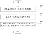
The second aspect of the present invention provides a method for controlling a data center evaporative cooling and waste heat recovery unit, which can be used for the data center evaporative cooling and waste heat recovery unit according to any of the above technical solutions, and the method for controlling the data center evaporative cooling and waste heat recovery unit includes: acquiring the dry bulb temperature and the wet bulb temperature of the outdoor environment; and controlling the cooling system and the compression system to work according to the dry bulb temperature and/or the wet bulb temperature.
The control method of the data center evaporative cooling and waste heat recovery unit provided by the invention can be used for the data center evaporative cooling and waste heat recovery unit in any technical scheme. Therefore, the evaporative cooling and waste heat recovery unit has all the beneficial effects of the data center evaporative cooling and waste heat recovery unit. In addition, in the process of controlling the evaporative cooling and waste heat recovery unit of the data center to operate, the dry bulb temperature of the outdoor environment and the wet bulb temperature of the outdoor environment are obtained; then, based on at least one of above-mentioned dry bulb temperature and wet bulb temperature, control cooling system and compression system work, guarantee air conditioning system to the regulation of the inside temperature of computer lab and room temperature, guarantee that the inside temperature of computer lab and humidity are in suitable environment, and then guarantee the life of the inside electrical equipment of computer lab.
Specifically, the operation of the cooling system and the compression system can be controlled according to the dry bulb temperature of the outdoor environment, the operation of the cooling system and the compression system can be controlled according to the wet bulb temperature of the outdoor environment, and the operation of the cooling system and the compression system can be controlled according to the dry bulb temperature and the wet bulb temperature of the outdoor environment.
According to the control method of the data center evaporative cooling and waste heat recovery unit in the technical scheme, the control method can also have the following additional technical characteristics:
in the technical scheme, when the outdoor dry bulb temperature is less than or equal to the dry bulb humidity threshold value, the compressor of the compression system and the cooling device of the cooling system are controlled to stop working.
According to the technical scheme, when the outdoor dry bulb temperature is smaller than or equal to the dry bulb humidity threshold value, the evaporative cooling and waste heat recovery unit is controlled to operate in a straight ventilation cooling mode. And in the straight ventilation cooling mode, the compressor of the compression system and the cooling device of the cooling system stop working. At the moment, outdoor fresh air sequentially flows through the air inlet valve, the filtering device, the cooling device, the first heat exchanging part of the second heat exchanging device, the first fan and the air supply outlet and then enters the machine room, and is used for cooling information equipment in the machine room. The opening degree of the air inlet valve is adjusted according to the heat productivity of the machine room and the return air temperature of the machine room, and the outdoor fresh air supply quantity is adjusted.
In addition, after returning air in the machine room enters the air exhaust channel through the air return inlet, the returning air can be exhausted to the outside from the first air valve and the third air valve; or the air can be discharged out of the room partially through the exhaust valve, and the air can be mixed with outdoor fresh air partially through the air inlet channel of the air mixing valve and then sent into the machine room. Partial return air and outdoor fresh air are mixed and then sent into the machine room, so that the phenomenon that equipment in the machine room is condensed due to the fact that the temperature of the fresh air is too low can be avoided (at the moment, the first air valve and the third air valve are closed, and the air mixing valve and the second fan are opened).
In any of the above technical solutions, when the dry bulb temperature is greater than the dry bulb temperature threshold and the wet bulb temperature is less than or equal to the wet bulb temperature threshold, the compressor of the compression system is controlled to stop working, and the cooling device of the cooling system is controlled to start working.
In the technical scheme, when the dry bulb temperature is greater than the dry bulb temperature threshold and the wet bulb temperature is less than or equal to the wet bulb temperature threshold, the data center evaporative cooling and waste heat recovery unit operates in a direct evaporative cooling mode. Under the direct evaporative cooling mode, the compressor of the compression system is controlled to stop working, the cooling device of the cooling system is controlled to start working, and the cooling effect on fresh air is improved through water evaporation cooling.
In addition, the control of each damper in the direct evaporative cooling mode is the same as in the straight ventilation cooling mode, and the discussion thereof will not be repeated.
In any of the above technical solutions, when the dry-bulb temperature is greater than the dry-bulb temperature threshold, the cooling device of the cooling system is controlled to stop working, the first air valve and the third air valve are opened, the second air valve and the air mixing valve are closed, the compressor of the compression system is controlled to start working, the first expansion valve and the second expansion valve are opened, and the third expansion valve is closed.
In the technical scheme, when the dry-bulb temperature is greater than the dry-bulb temperature threshold value, the data center evaporative cooling and waste heat recovery unit operates in a direct air cooling and mechanical cold supplement mode. The difference between the straight-through air cooling and mechanical supplementary cooling mode and the straight-through air cooling mode is as follows: in the mode, a compressor of the compression system, a first heat exchanger of the second heat exchange device, a second heat exchanger of the second heat exchange device, a first expansion valve and a second expansion valve are opened, and a third expansion valve is fully closed; the first air valve and the third air valve are opened, and the second air valve and the air mixing valve are closed. At the moment, the first heat exchange part is used as an evaporator, the second heat exchange part is used as a condenser, the first heat exchange part is used for supplementing cold and reducing temperature for outdoor fresh air, and heat of the second heat exchange part enters from the third air valve and is discharged from the exhaust valve (or enters from the exhaust valve and is discharged from the third air valve).
In any of the above technical solutions, when the wet bulb temperature is greater than the wet bulb temperature threshold, the cooling device of the cooling system is controlled to start operating, the first air valve and the third air valve are opened, the second air valve and the air mixing valve are closed, the compressor of the compression system is controlled to start operating, the first expansion valve and the second expansion valve are opened, and the third expansion valve is closed.
In the technical scheme, when the wet bulb temperature is greater than the wet bulb temperature threshold value, the data center evaporative cooling and waste heat recovery unit runs in a direct evaporative cooling and mechanical cold supplement mode. The direct evaporative cooling & mechanical cold makeup mode differs from the straight ventilation cooling & mechanical cold makeup mode in that: the cooling device of the cooling system operates and is used for carrying out primary cooling on outdoor fresh air and then carrying out secondary cooling by the first heat exchange part.
However, the cooling device needs to control the spraying water amount in the operation process, so that the overhigh fresh air humidity is avoided. The requirement on the spraying water quantity is to avoid condensation on the surface of the first heat exchange part.
In any of the above technical solutions, the method for controlling the data center evaporative cooling and waste heat recovery unit further includes: acquiring heat needing to be recovered of the first heat exchange device; and controlling the cooling system and the compression system to work according to the heat recovery requirement and the dry bulb temperature and/or the wet bulb temperature.
In the technical scheme, the heat needing to be recovered of the first heat exchange device is obtained, and the heat needing to be recovered of the first heat exchange device is used as the heat needed by a heat user; then, according to need retrieve heat and at least one in dry bulb temperature and the wet bulb temperature, control cooling system and compression system work, guarantee air conditioning system to the regulation of the inside temperature of computer lab and room temperature, guarantee that the inside temperature of computer lab and humidity are in suitable environment, and then guarantee the life of the inside electrical equipment of computer lab.
Therefore, in the process of controlling the unit to operate, the environment temperature and the environment humidity in the machine room can be ensured to be appropriate, the heat in the machine room can be recovered, and the technical effects of energy conservation and emission reduction are achieved.
In any of the above technical solutions, when the dry-bulb temperature is less than or equal to the dry-bulb temperature threshold and the heat to be recovered is greater than 0, the cooling device of the cooling system is controlled to stop working, the first air valve and the third air valve are closed, the second air valve is opened, and the compressor of the compression system is controlled to start working, the first expansion valve and the third expansion valve are opened, the second expansion valve is closed, and the reversing valve is reversed.
In the technical scheme, when the dry bulb temperature is less than or equal to the dry bulb temperature threshold value and a heat user needs to use heat (the heat needing to be recovered by the first heat exchange device is greater than 0), the data center evaporative cooling and waste heat recovery unit is controlled to move to directly pass through the ventilation cooling and waste heat recovery mode. Under the mode of motion straight ventilation cooling and waste heat recovery, outdoor fresh air sequentially flows through an air inlet valve, a filtering device, a cooling device, a first heat exchange part of a second heat exchange device, a first fan and an air supply outlet to enter a machine room and is used for cooling information equipment in the machine room; the opening of the air inlet valve is adjusted according to the heat productivity of the machine room and the return air temperature of the machine room, so that the outdoor fresh air supply quantity is adjusted; the cooling device does not operate.
A compressor, a first expansion valve and a third expansion valve of the compression system are opened, a reversing valve is reversed, a second heat exchange part is used as an evaporator, and a first heat conversion device is used as a condenser. The return water of the hot user enters the first heat conversion device, and is heated and then sent to the hot user. The second expansion valve is fully closed, and the first heat exchange part of the second heat exchange device is not used.
The first air valve and the third air valve are closed, the second air valve is opened, the machine room return air flows through the second heat exchanging part and transfers heat to the low-temperature refrigerant in the second heat exchanging part, and the machine room return air waste heat recycling is realized. In addition, the air mixing valve determines the opening state (fully opened or partially opened or fully closed) according to whether the return air and the fresh air need to be mixed.
In any of the above technical solutions, when the dry bulb temperature is greater than the dry bulb temperature threshold, the wet bulb temperature is less than or equal to the wet bulb temperature threshold, and the heat to be recovered is greater than 0, the cooling device of the cooling system is controlled to start working, the first air valve and the third air valve are closed, the second air valve is opened, the compressor of the compression system is controlled to start working, the first expansion valve and the third expansion valve are opened, the second expansion valve is closed, and the reversing valve is reversed.
In the technical scheme, when the dry bulb temperature is greater than the dry bulb temperature threshold, the wet bulb temperature is less than or equal to the wet bulb temperature threshold, and the hot user needs to use heat (the heat needing to be recovered by the first heat exchange device is greater than 0), the air conditioning system is controlled to operate a direct evaporative cooling and waste heat recovery mode, and the direct evaporative cooling and waste heat recovery mode is different from the direct air cooling and waste heat recovery mode in that: under direct evaporative cooling & waste heat recovery mode, the heat sink operation, through the evaporation cooling of moisture, improve the cooling effect to the new trend.
In any of the above technical solutions, when the dry-bulb temperature is greater than the dry-bulb temperature threshold and the heat to be recovered is greater than 0, the cooling device of the cooling system is controlled to stop working, the first air valve and the third air valve are closed, the second air valve is opened, the compressor of the compression system is controlled to start working, the first expansion valve, the second expansion valve and the third expansion valve are opened, and the reversing valve is reversed.
In the technical scheme, when the dry bulb temperature is greater than the dry bulb temperature threshold value and a heat user needs to use heat (the heat needing to be recovered by the first heat exchange device is greater than 0), the air conditioning system is controlled to operate a first sub-mode of a direct air cooling, mechanical supplementary cooling and waste heat recovery mode. In a first sub-mode of a straight ventilation cooling, mechanical cold supplement and waste heat recovery mode, a compressor, a first expansion valve, a second expansion valve and a third expansion valve are opened, and a reversing valve is reversed; at this time, the first heat exchanging part and the second heat exchanging part of the second heat exchanging device both serve as evaporators, and the first heat exchanging device serves as a condenser.
In addition, the first air valve and the third air valve are closed, the second air valve is opened, and the machine room return air flows through the second heat exchange part and transfers heat to the low-temperature refrigerant in the second heat exchange part. In addition, the air mixing valve determines the opening state (fully opened or partially opened or fully closed) according to whether the return air and the fresh air need to be mixed.
In a first sub-mode of the straight ventilation cooling, mechanical cold supplement and waste heat recovery mode, the compression system absorbs heat from the first heat exchange part and the second heat exchange part simultaneously to supply heat to a heat user, so that the function of supplying fresh air for cold supplement is realized, and the function of waste heat recovery is also realized.
In any of the above technical solutions, when the dry-bulb temperature is greater than the dry-bulb temperature threshold and the heat to be recovered is greater than 0, the cooling device of the cooling system is controlled to stop working, the first air valve and the third air valve are opened, the second air valve and the air mixing valve are closed, and the compressor of the compression system is controlled to start working, and the first expansion valve, the second expansion valve and the third expansion valve are opened.
In the technical scheme, when the dry bulb temperature is greater than the dry bulb temperature threshold value and a heat user needs to use heat (the heat needing to be recovered by the first heat exchange device is greater than 0), the air conditioning system is controlled to operate a second sub-mode of a direct air cooling, mechanical supplementary cooling and waste heat recovery mode. Under the through air cooling and mechanical supplementary cooling and waste heat recovery mode, the second sub-mode is different from the first sub-mode in that: the reversing valve does not reverse, the first air valve and the third air valve are opened, and the air mixing valve and the second air valve are closed.
At this time, the first heat exchange portion of the second heat exchange device serves as an evaporator, and the second heat exchanger portion and the first heat exchange device of the second heat exchange device both serve as condensers. The heat of the second heat exchanging part enters from the third air valve and is discharged from the exhaust valve (or enters from the exhaust valve and is discharged from the third air valve).
The sub-mode is used for taking away redundant heat through outdoor fresh air on the premise that fresh air cooling capacity is larger than heat demand of a heat user and the compression system meets requirements of fresh air cooling and heat supply of the heat user.
In any of the above technical solutions, when the wet bulb temperature is greater than the wet bulb temperature threshold and the heat to be recovered is greater than 0, the cooling device of the cooling system is controlled to start working, the first air valve and the third air valve are closed, the second air valve is opened, the compressor of the compression system is controlled to start working, the first expansion valve, the second expansion valve and the third expansion valve are opened, and the reversing valve is reversed.
In the technical scheme, when the wet bulb temperature is greater than the wet bulb temperature threshold value and the heat user needs to use the heat (the heat needing to be recovered by the first heat exchange device is greater than 0), the air conditioning system is controlled to operate the first sub-mode of the direct evaporative cooling and mechanical cold supplement and waste heat recovery mode. The first sub-mode of the direct evaporative cooling and mechanical supplementary cooling and waste heat recovery mode is different from the first sub-mode of the direct air cooling and mechanical supplementary cooling and waste heat recovery mode in that: the cooling device of the cooling system operates and is used for carrying out primary cooling on outdoor fresh air and then carrying out secondary cooling by the first heat exchange part of the second heat exchange device.
However, the cooling device needs to control the spraying water amount in the operation process, so that the overhigh fresh air humidity is avoided. The requirement on the spraying water quantity is to avoid condensation on the surface of the first heat exchange part.
In any of the above technical solutions, when the wet bulb temperature is greater than the wet bulb temperature threshold and the heat to be recovered is greater than 0, the cooling device of the cooling system is controlled to start working, the first air valve and the third air valve are closed, the second air valve is opened, and the compressor of the compression system is controlled to start working, and the first expansion valve, the second expansion valve and the third expansion valve are opened.
In the technical scheme, when the wet bulb temperature is greater than the wet bulb temperature threshold value and the heat user needs to use the heat (the heat needing to be recovered by the first heat exchange device is greater than 0), the air conditioning system is controlled to operate the second sub-mode of the direct evaporative cooling and mechanical cold supplement and waste heat recovery mode. In the direct evaporative cooling and mechanical cold compensation and waste heat recovery mode, the second sub-mode is different from the first sub-mode in that: the reversing valve does not reverse, the first air valve and the third air valve are opened, and the air mixing valve and the second air valve are closed.
At this time, the first heat exchange portion of the second heat exchange device serves as an evaporator, and the second heat exchanger portion and the first heat exchange device of the second heat exchange device both serve as condensers. The heat of the second heat exchanging part enters from the third air valve and is discharged from the exhaust valve (or enters from the exhaust valve and is discharged from the third air valve).
In addition, the air conditioning system may also operate an internal circulation mechanical refrigeration & waste heat recovery mode. Under the internal circulation mechanical refrigeration and waste heat recovery mode, the hot air in the machine room returns to the air inlet channel from the air exhaust channel, and the heat in the machine room is recovered and sent to the heat user. At this time, the first heat exchanging portion and the second heat exchanging portion of the second heat exchanging device are both used as evaporators of the compression system (only one of the first heat exchanging portion and the second heat exchanging portion may be opened, or all of the first heat exchanging portion and the second heat exchanging portion may be opened), and the second heat exchanging device is used as a condenser of the compression system.
In any of the above technical solutions, no matter what mode the air conditioning system is operating in, when the direction change valve is changed, a very small amount of refrigerant enters the capillary tube from the discharge port of the compressor through the direction change valve and then returns to the compressor. The capillary tube is set to maintain the circulation of refrigerant in the loop and avoid system fault caused by oil and liquid accumulating in the loop.
The third aspect of the present invention provides a control device for a data center evaporative cooling and waste heat recovery unit, comprising: a memory having a program stored thereon; and the processor can be used for executing programs so as to realize the control method of the data center evaporative cooling and waste heat recovery unit according to any technical scheme.
According to the control device of the data center evaporative cooling and waste heat recovery unit, provided by the invention, when the program stored on the memory is executed by the processor, the control method of the data center evaporative cooling and waste heat recovery unit in any technical scheme can be realized. Therefore, all the beneficial effects of the control method of the data center evaporative cooling and waste heat recovery unit are not discussed herein.
A fourth aspect of the present invention provides a readable storage medium, on which a program is stored, and when the program is processed and executed, the method for controlling the evaporative cooling and waste heat recovery unit of the data center according to any one of the above technical solutions is implemented.
When the program stored on the readable storage medium is executed, the method for controlling the data center evaporative cooling and waste heat recovery unit according to any one of the above technical solutions can be realized. Therefore, all the beneficial effects of the control method of the data center evaporative cooling and waste heat recovery unit are not discussed herein.
Additional aspects and advantages of the invention will be set forth in part in the description which follows, and in part will be obvious from the description, or may be learned by practice of the invention.
Drawings
The above and/or additional aspects and advantages of the present invention will become apparent and readily appreciated from the following description of the embodiments, taken in conjunction with the accompanying drawings of which:
FIG. 1 is a schematic diagram of a data center evaporative cooling and heat recovery unit in accordance with one embodiment of the present invention;
FIG. 2 is a schematic diagram of a data center evaporative cooling and heat recovery unit in accordance with yet another embodiment of the present invention;
FIG. 3 is a schematic diagram of a data center evaporative cooling and heat recovery unit in accordance with yet another embodiment of the present invention;
FIG. 4 is a schematic diagram of a compression system in the evaporative cooling and heat recovery unit of any of the data centers of FIGS. 1-3;
FIG. 5 is a schematic diagram of a data center evaporative cooling and heat recovery unit in accordance with yet another embodiment of the present invention;
FIG. 6 is a schematic diagram of a compression system in the data center evaporative cooling and heat recovery unit shown in FIG. 5;
FIG. 7 is a schematic diagram of a data center evaporative cooling and heat recovery unit in accordance with yet another embodiment of the present invention;
FIG. 8 is a schematic diagram of a compression system in the data center evaporative cooling and heat recovery unit shown in FIG. 7;
FIG. 9 is a flow chart of a method of controlling a data center evaporative cooling and heat recovery unit in accordance with one embodiment of the present invention;
FIG. 10 is a flow chart of a method of controlling a data center evaporative cooling and heat recovery unit in accordance with yet another embodiment of the present invention;
fig. 11 is a block diagram of a control device of the evaporative cooling and heat recovery unit of the data center according to an embodiment of the present invention.
Wherein, the correspondence between the reference numbers and the component names in fig. 1 to 8 is:
102, 104, 106, 110, 112, 114, 116, 118, 120, 122, third, 124, 126, 128, 130, 132, 134, 136, 138, 140, 142, 144, 146 capillary, 148, 150, 152, second, 154, 156 heat exchange pipeline.
Detailed Description
In order that the above objects, features and advantages of the present invention can be more clearly understood, a more particular description of the invention will be rendered by reference to the appended drawings. It should be noted that the embodiments and features of the embodiments of the present application may be combined with each other without conflict.
In the following description, numerous specific details are set forth in order to provide a thorough understanding of the present invention, however, the present invention may be practiced otherwise than as specifically described herein, and thus the scope of the present invention is not limited by the specific embodiments disclosed below.
The data center evaporative cooling and waste heat recovery unit, the control method thereof, the control device 400 thereof and the readable storage medium thereof according to some embodiments of the present invention are described below with reference to fig. 1 to 11. Wherein the arrows in fig. 1, 2, 3, 5 and 7 indicate the gas flow direction; also, the machine room is not shown in the figures, but it can be understood by those skilled in the art.
As shown in fig. 1, fig. 2, fig. 3, fig. 5, and fig. 7, a first embodiment of the present invention provides an evaporative cooling and waste heat recovery unit for a data center, which can be used to cool a machine room, so as to ensure a proper temperature in the machine room and to ensure the storage and use safety of electrical equipment in the machine room. The data center evaporative cooling and waste heat recovery unit comprises a cooling system and a compression system which are matched with each other.
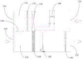
The cooling system includes an air duct (not shown in the air duct, but it can be seen that the air duct includes an air inlet channel 110 and an air outlet channel 112) and the cooling device 102. The air duct is provided with an air inlet side and an air outlet side which are communicated, and outdoor fresh air can enter the machine room from the air inlet side so as to cool the environment in the machine room; the air after heat exchange can be discharged out of the machine room from the air outlet side, and the whole air flow is ensured. The cooling device 102 is arranged on the air inlet side of the air duct and can contact with the air flow on the air inlet side to exchange heat in the operation process so as to reduce the temperature of the air entering the machine room and further improve the cooling effect on the machine room.
Further, the compression system includes a compressor 104, a first heat exchange device 106, a second heat exchange device (the second heat exchange device is not shown, but can be seen to include a first heat exchange portion 114 and/or a second heat exchange portion 116), and a heat exchange line 156 in cooperation. The first heat exchange device 106 is communicated with the compressor 104, and may be disposed inside the air duct or outside the air duct; the second heat exchange device is communicated with the first heat exchange device 106 and the compressor 104 and is arranged in the air duct; the heat exchange pipeline 156 has a water supply port and a water return port which are communicated, and the heat exchange pipeline 156 is in contact with the first heat exchange device and can exchange heat with the first heat exchange device in a contact manner, so that heat transfer is realized.
Specifically, when the compression system works, the operation of the compressor 104 enables the second heat exchange device to absorb heat from the air duct, so that the second heat exchange device can play a role in refrigeration at the air inlet side of the air duct and can also release heat at the air outlet side of the air duct; an external water source can enter the heat exchange pipeline 156 through the water return port, water can contact the first heat exchange device to exchange heat when flowing through the first heat exchange device, and then flows out of the heat exchange pipeline 156 through the water supply port, so that the heat exchanged water is supplied to a heat user, heat collection is achieved, and the purposes of energy conservation and emission reduction are achieved.
According to the data center evaporative cooling and waste heat recovery unit, the cooling system and the compression system are organically combined, so that the conventional data center evaporative cooling and waste heat recovery unit has additional functions of waste heat recovery, mechanical cold compensation and the like, on the premise of ensuring high energy efficiency evaporative cooling, high-efficiency mechanical cold compensation and waste heat recovery of a data center machine room are realized, switching can be performed in different operation modes based on different environments, the adaptability of the data center evaporative cooling and waste heat recovery unit is greatly improved, the data center evaporative cooling and waste heat recovery unit has the advantage of high natural cooling efficiency of the conventional evaporative cooling unit, the return air waste heat of the data center can be fully utilized, and the advantages of modularization and engineering removal of the data center evaporative cooling and waste heat recovery unit can be kept.
In addition, as a possible embodiment, the second heat exchanging device can also discharge heat at the air outlet side of the air duct, in this case, the second heat exchanging portion 116 of the second heat exchanging device is used as a condenser of the compression system, and the first heat exchanging device 106 does not work.
In addition, as a possible embodiment, the second heat exchanging device may also recover heat while discharging heat from the air outlet side of the air duct and supply the heat to the hot user, where both the second heat exchanging portion 116 of the second heat exchanging device and the first heat exchanging device 106 are used as condensers of the refrigeration system. As shown in fig. 1, fig. 2, fig. 3, fig. 5 and fig. 7, a second embodiment of the present invention provides an evaporative cooling and waste heat recovery unit for a data center, which includes a cooling system and a compression system used in cooperation.
The cooling system comprises an air duct and a cooling device 102, wherein the cooling device 102 is arranged on the air inlet side of the air duct; the compression system includes a compressor 104, a first heat exchange device 106, a second heat exchange device, and a heat exchange line 156, which cooperate to operate the compressor 104 such that the second heat exchange device absorbs heat from the air path.
Further, in this embodiment, the air duct includes an air intake passage 110 and an air discharge passage 112 communicating with each other. Wherein, the inlet end of the air intake channel 110 is communicated with the outdoor environment, the outlet end of the air intake channel 110 is communicated with the machine room, and the cooling device 102 is arranged in the air intake channel 110; when entering into the computer lab from inlet air channel 110, outdoor new trend can contact with heat sink 102 at first, if heat sink 102 is in the running state can carry out the heat transfer with the air current, if heat sink 102 stop work, can directly utilize the outside air to cool down for the computer lab.
In addition, the air return opening 134 of the exhaust channel 112 is communicated with the machine room, the low-temperature air is changed into hot air after heat exchange in the machine room, and the hot air can be exhausted through the exhaust channel 112 or enter the air inlet channel 110 again for recycling. The first heat exchange device 106 is arranged in the exhaust channel 112, and then contacts with hot air for heat exchange, so that the heat in the machine room is recovered, the collected heat is supplied to a heat user, and the purposes of energy conservation and emission reduction are achieved.
In a specific embodiment, the first heat exchanging device 106 is disposed in the exhaust duct 112, the first heat exchanging part 114 of the second heat exchanging device is disposed in the intake duct 110, and the second heat exchanging part 116 of the second heat exchanging device is disposed in the exhaust duct 112.
In the embodiment, the hot air returning from the exhaust duct 112 to the intake duct 110 occurs in the following cases:
the first condition is as follows: when the outside air temperature is too low, the outside air is directly sent into the machine room through the air inlet channel 110, and condensation in the machine room can be caused. Therefore, a part of the hot air is introduced into the air intake passage 110 from the air discharge passage 112, so that the cold air of low temperature from the outside is mixed with the hot air in the air duct and then is sent into the machine room. At this time, only a part of the hot air supply duct 110 is introduced from the discharge duct 112.
Case two: the hot air is completely returned to the air inlet channel 110 from the air outlet channel 112, and at the moment, the heat of the machine room is completely recovered and sent to the hot user. At this time, the first heat exchanging portion 114 of the second heat exchanging device and the first heat exchanging device 106 are both used as evaporators of the compression system (the first heat exchanging portion 114 and the first heat exchanging device 106 may be simultaneously turned on, or only one of them may be turned on), and the first heat exchanging device 106 is used as a condenser of the compression system.
In addition, the data center evaporative cooling and waste heat recovery unit that this embodiment provided, including like the whole beneficial effects of data center evaporative cooling and waste heat recovery unit of embodiment one, combine cooling system and compression system organic for conventional data center evaporative cooling and waste heat recovery unit have possessed extra functions such as waste heat recovery, machinery cold supplement, under the prerequisite of guaranteeing high energy efficiency evaporative cooling, have realized the high-efficient machinery cold supplement and the waste heat recovery utilization of data center computer lab.
As shown in fig. 7 and fig. 8, a third embodiment of the present invention provides an evaporative cooling and waste heat recovery unit for a data center, which includes a cooling system and a compression system used in cooperation.
As shown in fig. 7, the cooling system includes an air duct and a cooling device 102, and the cooling device 102 is disposed on an air inlet side of the air duct; the compression system comprises a compressor 104, a first heat exchange device 106, a second heat exchange device and a heat exchange pipeline 156 which are matched, wherein the compressor 104 is operated to enable the second heat exchange device to absorb heat from the air duct; the air duct includes an air inlet duct 110 and an air outlet duct 112 communicated with each other, and the first heat exchanging device 106 is disposed in the air outlet duct 112.
In this embodiment, further, as shown in fig. 7 and 8, the second heat exchanging means includes a first heat exchanging portion 114. The first heat exchanging portion 114 is disposed in the air intake channel 110 and is communicated with the first heat exchanging device 106 and the compressor 104. When the compression system is in an operating state, the first heat exchanging portion 114 is used in cooperation with the first heat exchanging device 106, the first heat exchanging portion 114 may be used as an evaporator, and the first heat exchanging device 106 may be used as a condenser.
Therefore, based on the cooperation between the first heat exchanging portion 114 and the first heat exchanging device 106, the air in the air inlet channel 110 is cooled by the first heat exchanging portion 114, so as to achieve the effect of cooling the machine room; the heat in the machine room is collected through the first heat exchange device 106, and meanwhile, the heat generated by the compression system is collected, so that the collected heat is supplied to a heat user, and the purposes of energy conservation and emission reduction are achieved.
In addition, the data center evaporative cooling and waste heat recovery unit that this embodiment provided, including like the whole beneficial effects of data center evaporative cooling and waste heat recovery unit of embodiment one, combine cooling system and compression system organic for conventional data center evaporative cooling and waste heat recovery unit have possessed extra functions such as waste heat recovery, machinery cold supplement, under the prerequisite of guaranteeing high energy efficiency evaporative cooling, have realized the high-efficient machinery cold supplement and the waste heat recovery utilization of data center computer lab.
As shown in fig. 5 and fig. 6, a fourth embodiment of the present invention provides an evaporative cooling and waste heat recovery unit for a data center, which includes a cooling system and a compression system used in cooperation.
As shown in fig. 5, the cooling system includes an air duct and a cooling device 102, and the cooling device 102 is disposed on an air inlet side of the air duct; the compression system comprises a compressor 104, a first heat exchange device 106, a second heat exchange device and a heat exchange pipeline 156 which are matched, wherein the compressor 104 is operated to enable the second heat exchange device to absorb heat from the air duct; the air duct includes an air inlet duct 110 and an air outlet duct 112 communicated with each other, and the first heat exchanging device 106 is disposed in the air outlet duct 112.
In this embodiment, further, as shown in fig. 6, the second heat exchanging means includes a second heat exchanging portion 116. Wherein, the second heat exchanging part 116 is arranged in the exhaust channel 112 and is communicated with the first heat exchanging device 106 and the compressor 104. When the compression system is in an operating state, the second heat exchanging portion 116 is used in cooperation with the first heat exchanging device 106, the second heat exchanging portion 116 may be used as an evaporator, and the first heat exchanging device 106 may be used as a condenser.
Therefore, based on the cooperation between the first heat exchanging part 114 and the first heat exchanging device 106, the second heat exchanging part 116 can absorb heat in the exhaust air channel 112 and transfer the part of heat to the first heat exchanging device 106, and the first heat exchanging device 106 can be used as a condenser to supply the part of heat to a heat user, thereby achieving the purposes of energy saving and emission reduction.
In addition, when the air after heat exchange with the second heat exchanging part 116 participates in cooling the machine room again, the cooling effect on the machine room can be further improved.
In addition, the data center evaporative cooling and waste heat recovery unit that this embodiment provided, including like the whole beneficial effects of data center evaporative cooling and waste heat recovery unit of embodiment one, combine cooling system and compression system organic for conventional data center evaporative cooling and waste heat recovery unit have possessed extra functions such as waste heat recovery, machinery cold supplement, under the prerequisite of guaranteeing high energy efficiency evaporative cooling, have realized the high-efficient machinery cold supplement and the waste heat recovery of data center computer lab and have utilized.
As shown in fig. 1, fig. 2 and fig. 3, a fifth embodiment of the present invention provides an evaporative cooling and waste heat recovery unit for a data center, which includes a cooling system and a compression system used in cooperation.
As shown in fig. 1, 2 and 3, the cooling system includes an air duct and a cooling device 102, and the cooling device 102 is disposed on an air inlet side of the air duct; the compression system comprises a compressor 104, a first heat exchange device 106, a second heat exchange device and a heat exchange pipeline 156 which are matched, wherein the compressor 104 is operated to enable the second heat exchange device to absorb heat from the air duct; the air duct includes an air inlet duct 110 and an air outlet duct 112 communicated with each other, and the first heat exchanging device 106 is disposed in the air outlet duct 112.
In this embodiment, further, as shown in fig. 1, fig. 2, fig. 3 and fig. 4, the second heat exchanging device includes a first heat exchanging portion 114 and a second heat exchanging portion 116 which are used in cooperation. The first heat exchanging portion 114 and the second heat exchanging portion 116 can be used in cooperation with the first heat exchanging device 106, and one or both of the first heat exchanging portion 114 and the second heat exchanging portion 116 can be used as an evaporator to absorb heat in the air inlet channel 110 or the air exhaust channel 112, so as to cool the machine room or recover heat in the machine room.
Specifically, when the first heat exchanging part 114 is used in cooperation with the first heat exchanging device 106, the first heat exchanging part 114 serves as an evaporator, and the first heat exchanging device 106 serves as a condenser. Therefore, the heat of the air intake channel 110 can be absorbed based on the first heat exchanging portion 114, so as to reduce the temperature in the machine room; the heat of the compression system itself may be collected based on the first heat exchanging device 106 to supply the portion of the heat to the hot user.
Specifically, as shown in fig. 1, 2 and 3, when the second heat exchanging part 116 is used in cooperation with the first heat exchanging device 106, the second heat exchanging part 116 functions as an evaporator, and the first heat exchanging device 106 functions as a condenser. Therefore, the heat of the compression system itself can be collected based on the first heat exchanging device 106 to supply the part of the heat to the heat user, based on the second heat exchanging part 116 absorbing the heat of the exhaust duct 112.
Specifically, as shown in fig. 1, 2 and 3, when the first heat exchanging part 114 and the second heat exchanging part 116 are used together with the first heat exchanging device 106, the first heat exchanging part 114 and the second heat exchanging part 116 simultaneously function as an evaporator, and the first heat exchanging device 106 functions as a condenser. Therefore, the heat of the compression system itself may be collected based on the first heat exchanging portion 114 to absorb the heat of the intake air passage 110, and the heat of the exhaust air passage 112 may be absorbed based on the second heat exchanging portion 116 to supply the heat to the hot user.
In addition, as a possible embodiment, when the first heat exchanging part 114 and the second heat exchanging part 116 are used together with the first heat exchanging device 106, the first heat exchanging part 114 may also be used as an evaporator, and the second heat exchanging part 116 and the first heat exchanging device 106 may also be used as a condenser.
In this embodiment, further, as shown in fig. 4, the compression system further includes a reversing component to realize switching of the compression system in different operation modes. Specifically, the reversing assembly includes a first expansion valve 118, a second expansion valve 120, a third expansion valve 122, and a reversing valve 124. Wherein, the first expansion valve 118 and the second expansion valve 120 are disposed at intervals on a flow path between the first heat exchanging part 114 and the second heat exchanging part 116, the first heat exchanging part 114 is disposed adjacent to the second heat exchanging part 116, and the second heat exchanging part 116 is disposed adjacent to the first heat exchanging part 114; the first heat exchanging part 114 is directly communicated with the compressor 104, and the second heat exchanging part 116 is communicated with the compressor 104 through a reversing valve 124; one end of the first heat exchange device 106 is connected to a flow path between the first expansion valve 118 and the second expansion valve 120 via the third expansion valve 122, and the other end of the first heat exchange device 106 is connected between the direction change valve 124 and the compressor 104.
In an embodiment, based on the cooperation of the first expansion valve 118, the second expansion valve 120, the third expansion valve 122 and the reversing valve 124, the compression system can be switched among different operation modes.
In an embodiment, the compressor 104, the first heat exchanging part 114, the second heat exchanging part 116, the first expansion valve 118, and the second expansion valve 120 of the compression system are opened, and the third expansion valve 122 is fully closed. In this case, the first heat exchanging part 114 serves as an evaporator, and the second heat exchanging part 116 serves as a condenser.
In the embodiment, the compressor 104, the first expansion valve 118, and the third expansion valve 122 are opened, the second expansion valve 120 is fully closed, the reversing valve 124 is reversed, the second heat exchanging part 116 serves as an evaporator, and the first heat exchanging device 106 serves as a condenser.
In the embodiment, the compressor 104, the first expansion valve 118, the second expansion valve 120, and the third expansion valve 122 are opened, the reversing valve 124 is reversed, the first heat exchanging part 114 and the second heat exchanging part 116 both serve as evaporators, and the first heat exchanging device 106 serves as a condenser.
In addition, the data center evaporative cooling and waste heat recovery unit that this embodiment provided, including like the whole beneficial effects of data center evaporative cooling and waste heat recovery unit of embodiment one, combine cooling system and compression system organic for conventional data center evaporative cooling and waste heat recovery unit have possessed extra functions such as waste heat recovery, machinery cold supplement, under the prerequisite of guaranteeing high energy efficiency evaporative cooling, have realized the high-efficient machinery cold supplement and the waste heat recovery utilization of data center computer lab.
Further to the first to fifth embodiments, as shown in fig. 1, 2, 3, 5 and 7, the compression system further includes a heat exchange line 156. Wherein, the heat exchange pipeline 156 is provided with a water supply port 126 and a water return port 128 which are communicated; the heat exchange line 156 is in contact with the first heat exchange device 106 and can exchange heat with the first heat exchange device 106 to realize heat transfer. Specifically, after the first heat exchanging device 106 recovers heat of the machine room, the external water source may enter the heat exchanging pipeline 156 through the water returning port 128, and when flowing through the first heat exchanging device 106, the water may contact the first heat exchanging device 106 for heat exchanging, and then flows out of the heat exchanging pipeline 156 through the water supplying port 126, so that the heat exchanged water is supplied to the heat user, and heat collection is achieved.
On the basis of the first to fifth embodiments, as shown in fig. 1, fig. 2, fig. 3, fig. 5 and fig. 7, the air inlet channel 110 has an air inlet and an air outlet 132 that are communicated, the air inlet is provided with an air inlet valve 130 at a position and is communicated with the outdoor environment, the air outlet 132 is communicated with the inside of the machine room, the temperature reducing device 102 and the first heat exchanging portion 114 of the second heat exchanging device are arranged between the air inlet and the air outlet 132, and outside fresh air can enter the inside of the machine room through the air inlet channel 110.
On the basis of the first to fifth embodiments, further, as shown in fig. 1, fig. 2, fig. 3, fig. 5 and fig. 7, the exhaust passage 112 has an air return 134 and an exhaust opening 154 which are communicated, the air return 134 is communicated with the machine room, an exhaust valve 136 is arranged at the exhaust opening 154, and the exhaust valve 136 is communicated with the outdoor environment; when the exhaust valve 136 is in the open state, air inside the machine room can enter the return air passage through the return air inlet 134 and be exhausted from the exhaust outlet 154.
On the basis of the first to fifth embodiments, as shown in fig. 1, 2, 3, 5 and 7, the data center evaporative cooling and waste heat recovery unit further includes an air mixing valve 138. The air mixing valve 138 is connected to the air intake channel 110 and the air exhaust channel 112, and can connect the air intake channel 110 and the air exhaust channel 112 or disconnect the air intake channel 110 and the air exhaust channel 112.
In the using process, when the air mixing valve 138 is in the closed state, the air entering the air exhaust channel 112 can be exhausted through the air outlet 154, so that the fresh air of the outdoor environment continuously enters the machine room through the air inlet channel 110, exchanges heat with the machine room and then is exhausted out of the room through the air exhaust channel 112. When the air mixing valve 138 is in the open state, the air entering the exhaust channel 112 can enter the air intake channel 110 again through the air mixing valve 138, so that the part of the air flow participates in heat exchange and temperature reduction again.
On the basis of the first to fifth embodiments, as shown in fig. 1, 2 and 3, the cooling system further includes a first air valve 140. Wherein, the first air valve 140 is disposed between the air return opening 134 and the first heat exchanging device 106, and is communicated with the exhaust channel 112. Thus, in use, when the first damper 140 is in a closed state, the gas entering the exhaust duct 112 can pass through the second heat exchanging part 116 of the second heat exchanging device and then be exhausted to the outside through the exhaust valve 136. When the first damper 140 is in the open state, the gas introduced into the exhaust passage 112 may be directly discharged from the first damper 140 without passing through the second heat exchanging part 116 of the second heat exchanging device, or a part of the gas may be discharged through the first damper 140 and a part of the gas may be discharged through the exhaust valve 136.
On the basis of the first to fifth embodiments, as shown in fig. 1 and 2, the cooling system further includes a second air valve 142 and a third air valve 144. The second air valve 142 is arranged inside the exhaust channel 112 and between the first air valve 140 and the exhaust valve 136, and the second air valve 142 can be used for blocking part of the exhaust channel 112 between the first air valve 140 and the exhaust valve 136; the third damper 144 is disposed between the second heat exchanging part 116 of the second heat exchanging device and the exhaust damper 136, and is communicated with the exhaust duct 112, so as to guide the air flow inside the exhaust duct 112 to the outside.
Thus, when the second air flap 142 is closed during use, the discharge passage 112 can be divided into two parts, and the air in the machine room can be discharged directly through the first air flap 140. The exhaust passage 112 is in communication with the outdoor environment through the exhaust port 154 (in this case, the exhaust valve 136 at the exhaust port 154 may be eliminated, or the exhaust valve 136 may be ensured to be in an open state), and is in communication with the outdoor environment through the third exhaust valve 144 in the open state.
At this time, in the case where the machine room needs mechanical cooling, but does not need waste heat recovery, one of the air outlet 154 and the third air valve 144 may be directly used as the air inlet, and the other of the air outlet 154 and the third air valve 144 may be used as the air outlet (depending on the installation direction of the second fan 152). In this way, ambient air at a relatively low outdoor temperature may be directly introduced to a position where the discharge duct 112 is provided with the second heat exchanging part 116, so that the part of the cold air is in contact with the second heat exchanging part 116 used as a condenser to cool the second heat exchanging part 116. Compared with the hot return air of the machine room, the cold air passing through the outdoor environment cools the second heat exchanging part 116, so that a better cooling effect can be achieved.
On the basis of the first to fifth embodiments, as shown in fig. 1, fig. 2, fig. 3, fig. 5, and fig. 7, the data center evaporative cooling and waste heat recovery unit further includes a first fan 150. The first fan 150 is disposed in the air intake channel 110, and can be used to drive outdoor fresh air to enter the machine room from the air intake channel 110.
On the basis of the first to fifth embodiments, as shown in fig. 1, fig. 2, fig. 3, fig. 5, and fig. 7, the data center evaporative cooling and waste heat recovery unit further includes a second fan 152. The second fan 152 is disposed in the exhaust duct 112 and between the second heat exchanging part 116 of the second heat exchanging device and the exhaust valve 136, and is configured to drive the air in the exhaust duct 112 to be exhausted to the outside.
Specifically, as shown in fig. 1, the second fan 152 may be disposed between the mixing damper 138 and the exhaust damper 136; as shown in fig. 2, it may be disposed between the air mixing valve 138 and the second heat exchanging part 116 of the second heat exchanging device.
Based on the first to fifth embodiments, as shown in fig. 1, fig. 2, fig. 3, fig. 5 and fig. 7, the data center evaporative cooling and waste heat recovery unit further includes a filtering device 148. The filtering device 148 is disposed in the air intake channel 110 and between the air mixing valve 138 and the cooling device 102 of the cooling system to filter the air entering the machine room and ensure the cleanliness of the air entering the machine room.
In addition to the first to fifth embodiments, as shown in fig. 1, 2, 3, 5 and 7, the temperature reducing device 102 is an evaporative cooling module. The evaporative cooling module can spray liquid in the operation process and absorb heat in a liquid evaporation mode.
A sixth embodiment of the present invention provides a method for controlling an evaporative cooling and waste heat recovery unit of a data center, which can be used for the evaporative cooling and waste heat recovery unit of the data center according to any one of the above technical solutions. Specifically, as shown in fig. 9, the method for controlling the evaporative cooling and waste heat recovery unit of the data center includes:
and step 204, controlling the cooling system and the compression system to work according to the dry bulb temperature and/or the wet bulb temperature.
In the process of controlling the evaporative cooling and waste heat recovery unit of the data center to operate, acquiring the dry bulb temperature of the outdoor environment and acquiring the wet bulb temperature of the outdoor environment; then, based on at least one of above-mentioned dry bulb temperature and wet bulb temperature, control cooling system and compression system work, guarantee air conditioning system to the regulation of the inside temperature of computer lab and room temperature, guarantee that the inside temperature of computer lab and humidity are in suitable environment, and then guarantee the normal work and the life of the inside electrical equipment of computer lab.
Specifically, the operation of the cooling system and the compression system can be controlled according to the dry bulb temperature of the outdoor environment, the operation of the cooling system and the compression system can be controlled according to the wet bulb temperature of the outdoor environment, and the operation of the cooling system and the compression system can be controlled according to the dry bulb temperature and the wet bulb temperature of the outdoor environment.
In this embodiment, in the process of controlling the operation of the cooling system and the compression system according to the dry bulb temperature and/or the wet bulb temperature, including but not limited to controlling the data center evaporative cooling and waste heat recovery unit to operate according to the following operation modes.
The first mode is as follows: a straight ventilation cooling mode. And when the outdoor dry bulb temperature is less than or equal to the dry bulb temperature threshold value, controlling the data center evaporative cooling and waste heat recovery unit to run in a direct ventilation cooling mode. And in the straight ventilation cooling mode, the compressor of the compression system and the cooling device of the cooling system stop working. At the moment, outdoor fresh air sequentially flows through the air inlet valve, the filtering device, the cooling device, the first heat exchanging part of the second heat exchanging device, the first fan and the air supply outlet and then enters the machine room, and is used for cooling information equipment in the machine room. The opening degree of the air inlet valve is adjusted according to the heat productivity of the machine room and the return air temperature of the machine room, and the outdoor fresh air supply quantity is adjusted.
In addition, after returning air in the machine room enters the air exhaust channel through the air return inlet, the returning air can be exhausted to the outside from the first air valve and the third air valve; or the air can be discharged out of the room partially through the exhaust valve, and the air can be mixed with outdoor fresh air partially through the air inlet channel of the air mixing valve and then sent into the machine room. Partial return air and outdoor fresh air are mixed and then sent into the machine room, so that the phenomenon that equipment in the machine room is condensed due to the fact that the temperature of the fresh air is too low can be avoided (at the moment, the first air valve and the third air valve are closed, and the air mixing valve and the second fan are opened).
And a second mode: direct evaporative cooling mode. And when the dry bulb temperature is greater than the dry bulb temperature threshold and the wet bulb temperature is less than or equal to the wet bulb temperature threshold, the data center evaporative cooling and waste heat recovery unit operates in a direct evaporative cooling mode. Under the direct evaporative cooling mode, the compressor of the compression system is controlled to stop working, the cooling device of the cooling system is controlled to start working, and the cooling effect on fresh air is improved through water evaporation cooling.
In addition, the control of each damper in the direct evaporative cooling mode is the same as in the straight ventilation cooling mode, and the discussion thereof will not be repeated.
And a third mode: direct air cooling and mechanical cold supplement mode. And when the dry-bulb temperature is greater than the dry-bulb temperature threshold value, the data center evaporative cooling and waste heat recovery unit operates in a direct air cooling and mechanical cold supplement mode. The difference between the straight-through air cooling and mechanical supplementary cooling mode and the straight-through air cooling mode is as follows: in the mode, a compressor of the compression system, a first heat exchanger of the second heat exchange device, a second heat exchanger of the second heat exchange device, a first expansion valve and a second expansion valve are opened, and a third expansion valve is fully closed; the first air valve and the third air valve are opened, and the second air valve and the air mixing valve are closed. At the moment, the first heat exchange part is used as an evaporator, the second heat exchange part is used as a condenser, the first heat exchange part is used for supplementing cold and reducing temperature for outdoor fresh air, and heat of the second heat exchange part enters from the third air valve and is discharged from the exhaust valve (or enters from the exhaust valve and is discharged from the third air valve).
And a fourth mode: direct evaporative cooling & mechanical cold makeup mode. When the wet bulb temperature is larger than the wet bulb temperature threshold value, the data center evaporative cooling and waste heat recovery unit operates in a direct evaporative cooling and mechanical cold supplement mode. The direct evaporative cooling & mechanical cold makeup mode differs from the straight ventilation cooling & mechanical cold makeup mode in that: the cooling device of the cooling system operates and is used for carrying out primary cooling on outdoor fresh air and then carrying out secondary cooling by the first heat exchange part.
However, the cooling device needs to control the spraying water amount in the operation process, so that the overhigh fresh air humidity is avoided. The requirement on the spraying water quantity is to avoid condensation on the surface of the first heat exchange part.
A seventh embodiment of the present invention provides a method for controlling an evaporative cooling and waste heat recovery unit of a data center, which can be used for the evaporative cooling and waste heat recovery unit of the data center according to any one of the above technical solutions. Specifically, as shown in fig. 10, the method for controlling the evaporative cooling and waste heat recovery unit of the data center includes:
and step 306, controlling the cooling system and the compression system to work according to the heat recovery requirement and the dry bulb temperature and/or the wet bulb temperature.
In the embodiment, the heat needing to be recovered of the first heat exchange device is obtained, and the heat needing to be recovered of the first heat exchange device is used as the heat needed by a heat user; then, according to need retrieve heat and at least one in dry bulb temperature and the wet bulb temperature, control cooling system and compression system work, guarantee air conditioning system to the regulation of the inside temperature of computer lab and room temperature, guarantee that the inside temperature of computer lab and humidity are in suitable environment, and then guarantee the life of the inside electrical equipment of computer lab.
Therefore, in the process of controlling the unit to operate, the environment temperature and the environment humidity in the machine room can be ensured to be appropriate, the heat in the machine room can be recovered, and the technical effects of energy conservation and emission reduction are achieved.
Specifically, the processes of controlling the operation of the cooling system and the compression system according to the heat recovery on demand and the dry bulb temperature and/or the wet bulb temperature include, but are not limited to, controlling the data center evaporative cooling and waste heat recovery unit to operate according to the following operation modes.
And a fifth mode: direct draft cooling & waste heat recovery mode. And when the dry bulb temperature is less than or equal to the dry bulb temperature threshold value and the heat user needs to use heat (the heat needing to be recovered by the first heat exchange device is greater than 0), controlling the data center evaporative cooling and waste heat recovery unit to move to directly enter an air cooling and waste heat recovery mode. Under the mode of motion straight ventilation cooling and waste heat recovery, outdoor fresh air sequentially flows through an air inlet valve, a filtering device, a cooling device, a first heat exchange part of a second heat exchange device, a first fan and an air supply outlet to enter a machine room and is used for cooling information equipment in the machine room; the opening of the air inlet valve is adjusted according to the heat productivity of the machine room and the return air temperature of the machine room, so that the outdoor fresh air supply quantity is adjusted; the cooling device does not operate.
A compressor, a first expansion valve and a third expansion valve of the compression system are opened, a reversing valve is reversed, a second heat exchange part is used as an evaporator, and a first heat conversion device is used as a condenser. The return water of the hot user enters the first heat conversion device, and is heated and then sent to the hot user. The second expansion valve is fully closed, and the first heat exchange part of the second heat exchange device is not used.
The first air valve and the third air valve are closed, the second air valve is opened, the machine room return air flows through the second heat exchanging part and transfers heat to the low-temperature refrigerant in the second heat exchanging part, and the machine room return air waste heat recycling is realized. In addition, the air mixing valve determines the opening state (fully opened or partially opened or fully closed) according to whether the return air and the fresh air need to be mixed.
Mode six: direct evaporative cooling & waste heat recovery mode. When the dry bulb temperature is greater than the dry bulb temperature threshold, the wet bulb temperature is less than or equal to the wet bulb temperature threshold, and a hot user needs to use heat (the heat needing to be recovered by the first heat exchange device is greater than 0), the air conditioning system is controlled to operate a direct evaporative cooling and waste heat recovery mode, and the direct evaporative cooling and waste heat recovery mode is different from the direct ventilation cooling and waste heat recovery mode in that: under direct evaporative cooling & waste heat recovery mode, the heat sink operation, through the evaporation cooling of moisture, improve the cooling effect to the new trend.
Mode seven: and a straight-through air cooling and mechanical supplementary cooling and waste heat recovery mode. When the dry bulb temperature is larger than the dry bulb temperature threshold value and a heat user needs to use heat (the heat needing to be recovered of the first heat exchange device is larger than 0), the air conditioning system is controlled to operate in a first sub-mode of a direct air cooling and mechanical supplementary cooling and waste heat recovery mode. In a first sub-mode of a straight ventilation cooling, mechanical cold supplement and waste heat recovery mode, a compressor, a first expansion valve, a second expansion valve and a third expansion valve are opened, and a reversing valve is reversed; at this time, the first heat exchanging part and the second heat exchanging part of the second heat exchanging device both serve as evaporators, and the first heat exchanging device serves as a condenser.
In addition, the first air valve and the third air valve are closed, the second air valve is opened, and the machine room return air flows through the second heat exchange part and transfers heat to the low-temperature refrigerant in the second heat exchange part. In addition, the air mixing valve determines the opening state (fully opened or partially opened or fully closed) according to whether the return air and the fresh air need to be mixed.
In a first sub-mode of the straight ventilation cooling, mechanical cold supplement and waste heat recovery mode, the compression system absorbs heat from the first heat exchange part and the second heat exchange part simultaneously to supply heat to a heat user, so that the function of supplying fresh air for cold supplement is realized, and the function of waste heat recovery is also realized.
In addition, when the dry bulb temperature is greater than the dry bulb temperature threshold value and a heat user needs to use heat (the heat needing to be recovered of the first heat exchange device is greater than 0), the air conditioning system is controlled to operate a second sub-mode of the direct air cooling and mechanical supplementary cooling and waste heat recovery mode. Under the through air cooling and mechanical supplementary cooling and waste heat recovery mode, the second sub-mode is different from the first sub-mode in that: the reversing valve does not reverse, the first air valve and the third air valve are opened, and the air mixing valve and the second air valve are closed.
At this time, the first heat exchange portion of the second heat exchange device serves as an evaporator, and the second heat exchanger portion and the first heat exchange device of the second heat exchange device both serve as condensers. The heat of the second heat exchanging part enters from the third air valve and is discharged from the exhaust valve (or enters from the exhaust valve and is discharged from the third air valve).
The sub-mode is used for taking away redundant heat through outdoor fresh air on the premise that fresh air cooling capacity is larger than heat demand of a heat user and the compression system meets requirements of fresh air cooling and heat supply of the heat user.
And a mode eight: and a straight-through air cooling and mechanical supplementary cooling and waste heat recovery mode. When the wet bulb temperature is larger than the wet bulb temperature threshold value and the heat user needs to use the heat (the heat needing to be recovered of the first heat exchange device is larger than 0), the air conditioning system is controlled to operate a first sub-mode of a direct evaporative cooling and mechanical supplementary cooling and waste heat recovery mode. The first sub-mode of the direct evaporative cooling and mechanical supplementary cooling and waste heat recovery mode is different from the first sub-mode of the direct air cooling and mechanical supplementary cooling and waste heat recovery mode in that: the cooling device of the cooling system operates and is used for carrying out primary cooling on outdoor fresh air and then carrying out secondary cooling by the first heat exchange part of the second heat exchange device. However, the cooling device needs to control the spraying water amount in the operation process, so that the overhigh fresh air humidity is avoided. The requirement on the spraying water quantity is to avoid condensation on the surface of the first heat exchange part.
In addition, the air conditioning system can be controlled to operate a second sub-mode of the direct evaporative cooling and mechanical cold supplement and waste heat recovery mode. In the direct evaporative cooling and mechanical cold compensation and waste heat recovery mode, the second sub-mode is different from the first sub-mode in that: the reversing valve does not reverse, the first air valve and the third air valve are opened, and the air mixing valve and the second air valve are closed.
At this time, the first heat exchange portion of the second heat exchange device serves as an evaporator, and the second heat exchanger portion and the first heat exchange device of the second heat exchange device both serve as condensers. The heat of the second heat exchanging part enters from the third air valve and is discharged from the exhaust valve (or enters from the exhaust valve and is discharged from the third air valve).
The mode nine: internal circulation mechanical refrigeration & waste heat recovery mode: the hot air in the machine room returns to the air inlet channel from the air exhaust channel, and the heat in the machine room is recovered and sent to a heat user. At this time, both the first heat exchanging portion and the second heat exchanging portion of the second heat exchanging device are used as evaporators of the compression system (only one of the first heat exchanging portion and the second heat exchanging portion may be opened, or all of the first heat exchanging portion and the second heat exchanging portion may be opened), and the first heat exchanging device is used as a condenser of the compression system.
In any of the above operating modes, no matter what mode the air conditioning system is operating in, when the reversing valve is reversed, a very small amount of refrigerant will pass from the discharge port of the compressor through the reversing valve into the capillary tube and then back to the compressor. The capillary tube is set to maintain the circulation of refrigerant in the loop and avoid system fault caused by oil and liquid accumulating in the loop.
As shown in fig. 11, an eighth embodiment of the present invention provides a control device 400 for a data center evaporative cooling and heat recovery unit, which includes a memory 402 and a processor 404.
When executed by the processor 404, the program stored in the memory 402 may implement the method for controlling the data center evaporative cooling and heat recovery unit according to the above embodiment. Therefore, all the beneficial effects of the control method of the data center evaporative cooling and waste heat recovery unit are not discussed herein.
The control device 400 for the data center evaporative cooling and waste heat recovery unit organically combines the cooling system and the compression system, so that the conventional data center evaporative cooling and waste heat recovery unit has additional functions of waste heat recovery, mechanical cold compensation and the like, and efficient mechanical cold compensation and waste heat recovery of a data center machine room are realized on the premise of ensuring high-energy-efficiency evaporative cooling.
A ninth embodiment of the present invention proposes a readable storage medium having a program stored thereon.
The readable storage medium stores a program which, when executed, implements the method for controlling the evaporative cooling and heat recovery unit of the data center according to any of the above embodiments. Therefore, all the beneficial effects of the control method of the data center evaporative cooling and waste heat recovery unit are not discussed herein.
In the specific embodiment, the cooling energy consumption of the machine room of the data center is very high and accounts for about 30% of the total energy consumption of the data center, the evaporative cooling can realize the high-energy-efficiency cooling of the data center by utilizing the dry air energy for refrigeration, and the evaporative cooling air treatment technology is widely applied in the industry. The data center runs all the year round, continuously generates a large amount of heat, and waste heat resources are very abundant, but most data center evaporative cooling air handling units in the industry at present do not have the waste heat recovery function, and a few schemes with the waste heat recovery function need to increase a waste heat recovery heat exchanger and a matched heat pump system, and the heat pump system has many pipelines and is complex in construction, so that the original advantages of modularization and engineering removal of the evaporative cooling air handling units are greatly weakened, and the comprehensive economic benefit of the waste heat recovery scheme of the existing evaporative cooling air handling units is not good.
The evaporative cooling air handling unit of the machine room of the existing data center does not have a waste heat recovery function, and in order to solve the problem, technicians usually adopt a scheme of adding a waste heat recovery heat exchanger and a matched heat pump system, so that the advantages of modularization and engineering removal of the evaporative cooling unit are greatly weakened, the engineering quantity of field construction is very high, and the comprehensive economic benefit is not good.
According to the invention, the evaporative cooling air treatment technology and the vapor compression refrigeration heating technology are organically combined, so that the evaporative cooling and waste heat recovery unit of the data center has additional functions of waste heat recovery, mechanical cold supplement and the like, on the premise of ensuring high energy efficiency evaporative cooling, the high-efficiency mechanical cold supplement and waste heat recovery of the data center are realized, and the comprehensive energy efficiency of the data center is greatly improved.
As shown in fig. 1 and 4, a first embodiment of the present invention provides a data center evaporative cooling and waste heat recovery unit, which includes a cooling system and a compression system used in cooperation. The cooling system comprises an air inlet valve 130, an air mixing valve 138, a filtering device 148, a cooling device 102, a first fan 150, an air supply outlet 132, an air return outlet 134, a first air valve 140, a second air valve 142, a third air valve 144, an exhaust air valve 136 and a second fan 152. The compression system comprises a first heat exchange device 106, a second heat exchange device (comprising a first heat exchange part 114 and a second heat exchange part 116), a reversing valve 124, a first expansion valve 118, a second expansion valve 120, a third expansion valve 122, a capillary tube 146, a water supply port 126 and a water return port 128. Wherein, the second fan 152 is disposed in the air intake channel 110 and between the air outlet 154 and the air mixing valve 138.
Outdoor fresh air enters from the air inlet valve 130, sequentially flows through the filtering device 148, the cooling device 102, the first heat exchanging part 114, the first fan 150 and the air supply outlet 132, and then enters the machine room. After the machine room return air enters the unit from the return air inlet 134, a plurality of flow paths exist according to different operation modes.
Specifically, the data center evaporative cooling and waste heat recovery unit can run at least the following eight operation modes, namely a direct air cooling mode, a direct evaporative cooling mode, a direct air cooling and mechanical supplementary cooling mode, a direct evaporative cooling and mechanical supplementary cooling mode, a direct air cooling and waste heat recovery mode, a direct evaporative cooling and waste heat recovery mode, a direct air cooling and mechanical supplementary cooling and waste heat recovery mode and a direct evaporative cooling and mechanical supplementary cooling and waste heat recovery mode.
For convenience of description, assume: the dry bulb temperature of the outdoor environment is To, the wet bulb temperature of the outdoor environment is Tow, the critical dry bulb temperature of the outdoor environment is To1(To1 > 0), the critical wet bulb temperature of the outdoor environment is To2(To2 >0 and To2 > To1), and the heat quantity To be recovered by the first heat exchange device 106 is Qh(i.e., the heat demand of the user is Qh) The heat productivity of the machine room is Qc。
The first method comprises the following steps: a straight ventilation cooling mode. And To is less than or equal To1, and operating a straight ventilation cooling mode. Outdoor fresh air sequentially flows through the air inlet valve 130, the filtering device 148, the cooling device 102, the first heat exchanging part 114, the first fan 150 and the air supply outlet 132 and then enters the machine room to cool information equipment in the machine room; the intake valve 130 generates heat Q according to the machine roomcAnd the opening degree of the return air temperature of the machine room is adjustedThe air supply quantity of outdoor fresh air is adjusted. The cooling device 102 is not operated in the straight-through air cooling mode.
The machine room return air enters the exhaust channel 112 through the return air inlet 134107 and then can be exhausted to the outside from the first air valve 140 and the third air valve 144; or the air can partially enter the air inlet channel 110 through the air outlet 154 to the outdoor, partially enter the air inlet channel 110 through the air mixing valve 138 and is mixed with the outdoor fresh air, and then is sent into the machine room (at this time, the first air valve 140 and the third air valve 144 are closed, and the second air valve 142 and the second fan 152 are opened), and the partially returned air and the outdoor fresh air are mixed and then are sent into the machine room, so that the condensation of the equipment in the machine room caused by the over-low temperature of the fresh air can be avoided.
And the second method comprises the following steps: direct evaporative cooling mode. When To is greater than To1 and Tow is less than or equal To2, the direct evaporative cooling mode is operated. This mode differs from the "straight ventilation cooling mode" in that: in this mode, the cooling device 102 operates to improve the cooling effect on fresh air by water evaporation cooling.
And the third is that: direct air cooling and mechanical cold supplement mode. When the purpose of saving water consumption is achieved or the temperature reduction device 102 is abnormal, if To is greater than To1, the straight ventilation cooling and mechanical supplementary cooling mode is operated.
This mode differs from the "straight ventilation cooling mode" in that: in this mode, the compressor 104, the first heat exchanging part 114, the second heat exchanging part 116, the first expansion valve 118, and the second expansion valve 120 of the compression system are opened, and the third expansion valve 122 is fully closed; the first air valve 140 and the third air valve 144 are opened, and the second air valve 142 and the air mixing valve 138 are closed.
The first heat exchanging part 114 serves as an evaporator, the second heat exchanging part 116 serves as a condenser, the first heat exchanging part 114 is used for supplementing cold and reducing temperature for outdoor fresh air, and heat of the second heat exchanging part 116 is taken away by the outdoor fresh air which enters through the third air valve 144 and is discharged from the air discharging valve 136 (or enters through the air discharging valve 136 and is discharged from the third air valve 144).
The machine room return air enters the exhaust channel 112 through the machine room return air inlet 134 and is directly exhausted to the outside through the first air valve 140.
It should be noted that when To > To1, the direct evaporative cooling mode is first operated, and the direct ventilation cooling and mechanical cooling mode is switched To when abnormality occurs in the cooling device 102 or in order To reduce the energy.
And fourthly: straight-through air cooling&And (5) a mechanical cold supplement mode. When T isow>To2, direct evaporative cooling&And (5) a mechanical cold supplement mode. This mode and "straight draft cooling&The mechanical cold supplement mode "is distinguished in that: the cooling device 102 of the cooling system unit operates, and the cooling device 102 is used for carrying out primary cooling on outdoor fresh air and then carrying out secondary cooling by the first heat exchanging part 114.
However, the cooling device 102 needs to control the amount of sprayed water during the operation process, so as to avoid overhigh humidity of the fresh air. The requirement for the amount of sprayed water is to avoid condensation on the surface of the first heat exchanging portion 114.
And a fifth mode: straight-through air cooling&And (5) a mechanical cold supplement mode. When To is less than or equal To1 and Qh>0 hour, the operation is directly ventilated for cooling&And (4) a waste heat recovery mode. Outdoor fresh air sequentially flows through the air inlet valve 130, the filtering device 148, the cooling device 102, the first heat exchanging part 114, the first fan 150 and the air supply opening 132106 and then enters the machine room to be used for cooling information equipment in the machine room; the intake valve 130 generates heat Q according to the machine roomcThe opening degree of the return air temperature of the machine room is adjusted, so that the adjustment of the air supply quantity of outdoor fresh air is realized; the temperature reduction device 102 is not operating.
The compressor 104, the first expansion valve 118, and the third expansion valve 122 are opened, the direction change valve 124 is changed, the second heat exchanging part 116 serves as an evaporator, and the first heat exchanging device 106 serves as a condenser. The hot user return water enters the first heat exchange device 106 through the water return port 128, is heated and is sent to the hot user through the water supply port 126. The second expansion valve 120 is fully closed and the first heat exchanging part 114 is not used.
The first air valve 140 and the third air valve 144 are closed, the second air valve 142 is opened, and the machine room return air flows through the second heat exchanging part 116 and transfers heat to the low-temperature refrigerant in the second heat exchanging part 116, so that the waste heat of the machine room return air is recycled. In addition, the mixing valve 138 determines its open state (fully open or partially open or fully closed) depending on whether it is necessary to mix the return air with the fresh air.
And a sixth mode: direct evaporative cooling & waste heat recovery mode. When To is greater than To1, Tow is less than or equal To To2 and Qh is greater than 0, the direct evaporative cooling and waste heat recovery mode is operated. This mode differs from the "straight ventilation cooling & waste heat recovery mode" in that: in this mode, the cooling device 102 operates to improve the cooling effect on fresh air by water evaporation cooling.
Seventh, the method comprises: and a straight-through air cooling and mechanical supplementary cooling and waste heat recovery mode. When the purpose of saving water consumption or the operation of the evaporative cooling module is abnormal, if To is greater than To1 and Qh is greater than 0, the direct ventilation cooling and mechanical supplementary cooling and waste heat recovery mode is operated. The mode has two sub-modes, namely a sub-mode I and a sub-mode II:
the first sub-mode comprises the following steps: the compressor 104, the first expansion valve 118, the second expansion valve 120, and the third expansion valve 122 are opened, the direction change valve 124 is changed over, the first heat exchanging part 114 and the second heat exchanging part 116 both function as evaporators, and the first heat exchanging device 106 functions as a condenser.
The first air valve 140 and the third air valve 144 are closed, the second air valve 142 is opened, and the machine room return air flows through the second heat exchanging part 116 and transfers heat to the low-temperature refrigerant in the second heat exchanging part 116. In addition, the mixing valve 138 determines its open state (fully open or partially open or fully closed) depending on whether it is necessary to mix the return air with the fresh air.
In this sub-mode, the compression system absorbs heat from the first heat exchanging portion 114 and the second heat exchanging portion 116 at the same time, and supplies heat to the hot users, i.e. the function of supplementing cold to the fresh air and the function of recovering waste heat are realized.
A second sub-mode: the first sub-mode is different in that: the direction change valve 124 is not changed, the first air valve 140 and the third air valve 144 are opened, and the air mixing valve 138102 and the second air valve 142 are closed.
In this case, the first heat exchanging part 114 serves as an evaporator, and the second heat exchanging part 116 and the second heat exchanging device serve as condensers. The heat of the second heat exchanging part 116 is taken away by the fresh outdoor air entering through the third air valve 144 and exiting through the air outlet 154 (or entering through the air outlet 154 and exiting through the third air valve 144).
The sub-mode is used for supplementing cold quantity of fresh air to be larger than heat quantity Q required by heat usershUnder the condition of (2), the compression system takes away the redundant heat through outdoor fresh air on the premise of meeting the requirements of fresh air cold supplement and heat supply of hot users.
Notably, To>To1 and Qh>When 0, firstly, the first sub-mode is operated, and the cold supplement quantity of the fresh air is larger than the heat quantity Q required by a heat userhIn case (2), the second submode is operated.
An eighth method: direct evaporative cooling & mechanical cold supplement & waste heat recovery mode. When Tow > To2 and Qh >0, the direct evaporative cooling & mechanical make-up & waste heat recovery mode is run.
The mode is different from a straight ventilation cooling and mechanical supplementary cooling and waste heat recovery mode in that: the cooling device 102 of the cooling system operates, and the cooling device 102 is used for carrying out primary cooling on outdoor fresh air and then carrying out secondary cooling by the first heat exchanging part 114.
However, the cooling device 102 needs to control the amount of sprayed water during the operation process, so as to avoid overhigh humidity of the fresh air. The requirement for the amount of sprayed water is to avoid condensation on the surface of the first heat exchanging portion 114.
Ninth, the method comprises the following steps: internal circulation mechanical refrigeration & waste heat recovery mode: the hot air in the machine room returns to the air inlet channel 110 from the air outlet channel 112, and the heat in the machine room is recovered and sent to the hot users. In this case, the first heat exchanging portion 114 and the second heat exchanging portion 116 of the second heat exchanging device are both used as evaporators of the compression system (only one of the first heat exchanging portion and the second heat exchanging portion may be turned on, or both of them may be turned on), and the first heat exchanging device 106 is used as a condenser of the compression system.
Additionally, in all modes, when the reversing valve 124 is reversed, very little refrigerant will pass from the discharge of the compressor 104 through the reversing valve 124 into the capillary tube 146 and back to the compressor 104. The capillary tube 146 is provided to maintain the refrigerant circulation in the circuit, thereby avoiding system failure due to oil accumulation and liquid accumulation in the circuit.
As shown in fig. 2, a second embodiment of the present invention provides another data center evaporative cooling and waste heat recovery unit, which is different from the first embodiment in that: the position where the second fan 152 is disposed. Wherein, the second fan 152 is arranged in the exhaust channel 112 and between the second heat exchanging part 116 and the air mixing valve 138.
As shown in fig. 3 and 4, a third embodiment of the present invention provides another data center evaporative cooling and heat recovery unit, which is different from the first embodiment in that: the second air flap 142 and the third air flap 144 are eliminated. Correspondingly, the operation mode of the data center evaporative cooling and waste heat recovery unit is slightly different from that of the first embodiment, and specifically the following steps are carried out:
the first method comprises the following steps: a straight ventilation cooling mode. The difference from the first embodiment is that: the machine room return air enters the exhaust channel 112 through the return air inlet 134 and then can be exhausted to the outside from the first air valve 140; or the air can be partially exhausted outdoors through the first air inlet, partially enters the air inlet channel 110 through the air mixing valve 138, is mixed with outdoor fresh air and then is sent into the machine room (at the moment, the first air valve 140 is closed, and the second fan 152 is opened), and partially returned air and the outdoor fresh air are mixed and then are sent into the machine room, so that the phenomenon that the temperature of the fresh air is too low to cause condensation of equipment in the machine room can be avoided.
And the second method comprises the following steps: direct evaporative cooling mode. When To is greater than To1 and Tow is less than or equal To2, the direct evaporative cooling mode is operated. This mode differs from the "straight ventilation cooling mode" in that: in this mode, the cooling device 102 operates to improve the cooling effect on fresh air by water evaporation cooling.
And the third is that: direct air cooling and mechanical cold supplement mode. The difference from the first embodiment is that: the first air valve 140 is closed and machine room return air enters through the return air inlet 134 and exits through the exhaust valve 136.
And fourthly: direct evaporative cooling & mechanical cold makeup mode. When Tow > To2, the direct evaporative cooling & mechanical cold-supplement mode is operated. This mode differs from the "straight ventilation cooling & mechanical supplementary cooling mode" in that: the cooling device 102 of the cooling system operates, and the cooling device 102 is used for carrying out primary cooling on outdoor fresh air and then carrying out secondary cooling by the first heat exchanging part 114.
However, the cooling device 102 needs to control the amount of sprayed water during the operation process, so as to avoid overhigh humidity of the fresh air. The requirement for the amount of sprayed water is to avoid condensation on the surface of the first heat exchanging portion 114.
And a fifth mode: direct draft cooling & waste heat recovery mode. The difference from the first embodiment is that: the first air valve 140 is closed and machine room return air enters through the return air inlet 134 and exits through the exhaust valve 136. In addition, the mixing valve 138 determines its open state (fully open or partially open or fully closed) depending on whether it is necessary to mix the return air with the fresh air.
And a sixth mode: direct evaporative cooling & waste heat recovery mode. When To is greater than To1, Tow is less than or equal To To2 and Qh is greater than 0, the direct evaporative cooling and waste heat recovery mode is operated. This mode differs from the "straight ventilation cooling & waste heat recovery mode" in that: in this mode, the cooling device 102 operates to improve the cooling effect on fresh air by water evaporation cooling.
Seventh, the method comprises: and a straight-through air cooling and mechanical supplementary cooling and waste heat recovery mode. The difference from the first embodiment is that: the first air valve 140 is closed and machine room return air enters through the return air inlet 134 and exits through the exhaust valve 136.
An eighth method: direct evaporative cooling & mechanical cold supplement & waste heat recovery mode. And when Tow is greater than To2 and Qh is greater than 0, operating the direct evaporative cooling and mechanical supplementary cooling and waste heat recovery mode. The mode is different from a straight ventilation cooling and mechanical supplementary cooling and waste heat recovery mode in that: the cooling device 102 of the cooling system operates, and the cooling device 102 is used for carrying out primary cooling on outdoor fresh air and then carrying out secondary cooling by the first heat exchanging part 114.
However, the cooling device 102 needs to control the amount of sprayed water during the operation process, so as to avoid overhigh humidity of the fresh air. The requirement for the amount of sprayed water is to avoid condensation on the surface of the first heat exchanging portion 114.
As shown in fig. 5 and 6, a fourth embodiment of the present invention provides another data center evaporative cooling and waste heat recovery unit, which is different from the first embodiment in that the first heat exchanging part 114, the first air valve 140, the second air valve 142 and the third air valve 144 are eliminated. Therefore, the data center evaporative cooling and waste heat recovery unit provided by the embodiment does not have a mechanical cold compensation function, and exhaust waste heat is recovered through the compression system, so that hot water is output to the outside after the quality of the waste heat is improved.
As shown in fig. 7 and 8, a fifth embodiment of the present invention provides another data center evaporative cooling and waste heat recovery unit, which is different from the first embodiment in that the second heat exchanging part 116, the first air valve 140, the second air valve 142, and the third air valve 144 are eliminated. Therefore, the data center evaporative cooling and waste heat recovery unit provided by this embodiment is used for recovering waste heat in the mixed air mode and the return air mode, and the quality of the waste heat is improved and hot water is output to the outside through the compression system.
In the description of the present invention, the terms "plurality" or "a plurality" refer to two or more, and unless otherwise specifically limited, the terms "upper", "lower", and the like indicate orientations or positional relationships based on the orientations or positional relationships shown in the drawings, and are merely for convenience in describing the present invention and simplifying the description, but do not indicate or imply that the referred device or element must have a specific orientation, be constructed in a specific orientation, and be operated, and thus should not be construed as limiting the present invention; the terms "connected," "mounted," "secured," and the like are to be construed broadly and include, for example, fixed connections, removable connections, or integral connections; may be directly connected or indirectly connected through an intermediate. The specific meanings of the above terms in the present invention can be understood by those skilled in the art according to specific situations.
In the description herein, the description of the terms "one embodiment," "some embodiments," "specific embodiments," etc., means that a particular feature, structure, material, or characteristic described in connection with the embodiment or example is included in at least one embodiment or example of the invention. In this specification, the schematic representations of the terms used above do not necessarily refer to the same embodiment or example. Furthermore, the particular features, structures, materials, or characteristics described may be combined in any suitable manner in any one or more embodiments or examples.
The above is only a preferred embodiment of the present invention, and is not intended to limit the present invention, and various modifications and changes will occur to those skilled in the art. Any modification, equivalent replacement, or improvement made within the spirit and principle of the present invention should be included in the protection scope of the present invention.
Claims (23)
1. The utility model provides a data center evaporative cooling and waste heat recovery unit, can be used to the cooling of computer lab, its characterized in that, data center evaporative cooling and waste heat recovery unit includes:
a cooling system, the cooling system comprising:
the air duct is communicated with the machine room;
the cooling device is arranged on the air inlet side of the air duct and can be used for cooling the machine room;
a compression system, the compression system comprising:
a compressor;
the first heat exchange device is communicated with the compressor;
the second heat exchange device is communicated with the first heat exchange device and the compressor, is positioned in the air duct and can absorb heat from the air duct;
the heat exchange pipeline is provided with a water supply port and a water return port which are communicated, and the first heat exchange device can be used for supplying heat to the heat exchange pipeline.
2. The data center evaporative cooling and waste heat recovery unit of claim 1, wherein the air duct comprises:
the air inlet channel is communicated with the machine room, and the cooling device is positioned in the air inlet channel;
and the air exhaust channel is communicated with the machine room, and the first heat exchange device is arranged in the air exhaust channel.
3. The data center evaporative cooling and waste heat recovery unit of claim 2, wherein the second heat exchange device comprises:
and the first heat exchanging part is arranged in the air inlet channel and communicated with the first heat exchanging device and the compressor.
4. The data center evaporative cooling and waste heat recovery unit of claim 2, wherein the second heat exchange device comprises:
and the second heat exchange part is arranged in the exhaust channel and communicated with the first heat exchange device and the compressor.
5. The data center evaporative cooling and waste heat recovery unit of claim 2, wherein the second heat exchange device comprises:
the first heat exchanging part is arranged in the air inlet channel and communicated with the compressor;
the second heat exchanging part is arranged in the exhaust channel, communicated with the first heat exchanging part and the first heat exchanging device and communicated with the compressor.
6. The data center evaporative cooling and waste heat recovery unit of claim 5, wherein the compression system further comprises:
a first expansion valve disposed between the first heat exchanging part and the second heat exchanging part;
a second expansion valve disposed between the first expansion valve and the second heat exchange unit;
the reversing valve is arranged between the first heat exchange device and the compressor;
and one end of the first heat exchange device is communicated with one end of the compressor communicated with the reversing valve, and the other end of the first heat exchange device is communicated between the first expansion valve and the second expansion valve through the third expansion valve.
7. The data center evaporative cooling and waste heat recovery unit of any of claims 2 to 6,
the air inlet channel comprises an air inlet valve and an air supply outlet, and the air supply outlet is communicated with the machine room;
the air exhaust channel comprises an air return inlet and an air exhaust outlet which are communicated, and the air return inlet is communicated with the machine room;
the data center evaporative cooling and waste heat recovery unit further comprises an air mixing valve, and the air mixing valve is communicated with the air inlet channel and the air exhaust channel;
the data center evaporative cooling and waste heat recovery unit further comprises an exhaust valve, and the exhaust valve is arranged at the exhaust port.
8. The data center evaporative cooling and waste heat recovery unit of claim 7, wherein the cooling system further comprises:
and the first air valve is positioned between the air return opening and the first heat exchange device and communicated with the air exhaust channel.
9. The data center evaporative cooling and waste heat recovery unit of claim 8, wherein the cooling system further comprises:
the second air valve is arranged in the air exhaust channel and is positioned between the first air valve and the air exhaust valve;
and the third air valve is positioned between the first heat exchange device and the exhaust valve and communicated with the exhaust channel.
10. A control method for a data center evaporative cooling and waste heat recovery unit, which can be used for the data center evaporative cooling and waste heat recovery unit according to any one of claims 1 to 9, and comprises:
acquiring the dry bulb temperature and the wet bulb temperature of the outdoor environment;
and controlling the cooling system and the compression system to work according to the dry bulb temperature and/or the wet bulb temperature.
11. The method for controlling a data center evaporative cooling and waste heat recovery unit of claim 10,
and when the dry bulb temperature is less than or equal to the dry bulb temperature threshold value, controlling the compressor of the compression system and the cooling device of the cooling system to stop working.
12. The method for controlling a data center evaporative cooling and waste heat recovery unit of claim 10,
and when the dry bulb temperature is greater than the dry bulb temperature threshold value and the wet bulb temperature is less than or equal to the wet bulb temperature threshold value, controlling the compressor of the compression system to stop working and controlling the cooling device of the cooling system to start working.
13. The method for controlling a data center evaporative cooling and waste heat recovery unit of claim 10,
and when the dry bulb temperature is higher than the dry bulb temperature threshold value, controlling a cooling device of the cooling system to stop working, opening a first air valve and a third air valve, and closing a second air valve and an air mixing valve, and controlling a compressor of the compression system to start working, opening a first expansion valve and a second expansion valve, and closing a third expansion valve.
14. The method for controlling a data center evaporative cooling and waste heat recovery unit of claim 10,
and when the wet bulb temperature is higher than the wet bulb temperature threshold value, controlling a cooling device of the cooling system to start working, opening a first air valve and a third air valve, and closing a second air valve and an air mixing valve, and controlling a compressor of the compression system to start working, opening a first expansion valve and a second expansion valve, and closing a third expansion valve.
15. The method for controlling the data center evaporative cooling and waste heat recovery unit of any one of claims 10 to 14, further comprising:
acquiring the heat quantity to be recovered of the first heat exchange device;
and controlling the cooling system and the compression system to work according to the heat needing to be recovered and the dry bulb temperature and/or the wet bulb temperature.
16. The method of claim 15, wherein the control unit is further configured to control the evaporative cooling and waste heat recovery unit,
and when the temperature of the dry bulb is less than or equal to a dry bulb temperature threshold value and the heat to be recovered is more than 0, controlling a cooling device of the cooling system to stop working, closing a first air valve and a third air valve, opening a second air valve, controlling a compressor of the compression system to start working, opening a first expansion valve and a third expansion valve, closing a second expansion valve and reversing a reversing valve.
17. The method of claim 15, wherein the control unit is further configured to control the evaporative cooling and waste heat recovery unit,
and when the dry bulb temperature is greater than a dry bulb temperature threshold value, the wet bulb temperature is less than or equal to a wet bulb temperature threshold value, and the heat to be recovered is greater than 0, controlling a cooling device of the cooling system to start working, closing a first air valve and a third air valve, opening a second air valve, controlling a compressor of the compression system to start working, opening the first expansion valve and the third expansion valve, closing the second expansion valve, and reversing a reversing valve.
18. The method of claim 15, wherein the control unit is further configured to control the evaporative cooling and waste heat recovery unit,
when the dry bulb temperature is greater than a dry bulb temperature threshold value and the heat to be recovered is greater than 0, controlling a cooling device of the cooling system to stop working, closing a first air valve and a third air valve, opening a second air valve, controlling a compressor of the compression system to start working, opening a first expansion valve, a second expansion valve and a third expansion valve, and reversing a reversing valve.
19. The method of claim 15, wherein the control unit is further configured to control the evaporative cooling and waste heat recovery unit,
and when the dry bulb temperature is greater than a dry bulb temperature threshold value and the heat to be recovered is greater than 0, controlling a cooling device of the cooling system to stop working, opening a first air valve and a third air valve, closing a second air valve and an air mixing valve, and controlling a compressor of the compression system to start working, and opening a first expansion valve, a second expansion valve and a third expansion valve.
20. The method of claim 15, wherein the control unit is further configured to control the evaporative cooling and waste heat recovery unit,
and when the wet bulb temperature is greater than a wet bulb temperature threshold value and the heat to be recovered is greater than 0, controlling a cooling device of the cooling system to start working, closing a first air valve and a third air valve, opening a second air valve, controlling a compressor of the compression system to start working, opening a first expansion valve, a second expansion valve and a third expansion valve, and reversing a reversing valve.
21. The method of claim 15, wherein the control unit is further configured to control the evaporative cooling and waste heat recovery unit,
and when the wet bulb temperature is greater than a wet bulb temperature threshold value and the heat to be recovered is greater than 0, controlling a cooling device of the cooling system to start working, closing a first air valve and a third air valve, opening a second air valve, and controlling a compressor of the compression system to start working, and opening a first expansion valve, a second expansion valve and a third expansion valve.
22. A control device for a data center evaporative cooling and waste heat recovery unit is characterized by comprising:
a memory having a program stored thereon;
a processor operable to execute the program to implement the method of controlling a data centre evaporative cooling and heat recovery unit according to any one of claims 10 to 21.
23. A readable storage medium on which a program is stored, wherein the program, when executed by a processor, implements the method of controlling a data center evaporative cooling and heat recovery unit according to any one of claims 10 to 21.
Priority Applications (1)
| Application Number | Priority Date | Filing Date | Title |
|---|---|---|---|
| CN202110481470.4A CN113175715B (en) | 2021-04-30 | 2021-04-30 | Data center evaporative cooling and waste heat recovery unit and control method and device thereof |
Applications Claiming Priority (1)
| Application Number | Priority Date | Filing Date | Title |
|---|---|---|---|
| CN202110481470.4A CN113175715B (en) | 2021-04-30 | 2021-04-30 | Data center evaporative cooling and waste heat recovery unit and control method and device thereof |
Publications (2)
| Publication Number | Publication Date |
|---|---|
| CN113175715A true CN113175715A (en) | 2021-07-27 |
| CN113175715B CN113175715B (en) | 2022-08-30 |
Family
ID=76925929
Family Applications (1)
| Application Number | Title | Priority Date | Filing Date |
|---|---|---|---|
| CN202110481470.4A Active CN113175715B (en) | 2021-04-30 | 2021-04-30 | Data center evaporative cooling and waste heat recovery unit and control method and device thereof |
Country Status (1)
| Country | Link |
|---|---|
| CN (1) | CN113175715B (en) |
Cited By (3)
| Publication number | Priority date | Publication date | Assignee | Title |
|---|---|---|---|---|
| CN113669810A (en) * | 2021-08-04 | 2021-11-19 | 中兴通讯股份有限公司 | Indirect evaporative cooling apparatus |
| CN114413366A (en) * | 2022-01-25 | 2022-04-29 | 广东美的暖通设备有限公司 | Evaporative cooling unit with heat recovery function and control method thereof |
| CN115342464A (en) * | 2022-09-05 | 2022-11-15 | 珠海格力电器股份有限公司 | Heat exchange device, control method and air conditioner |
Citations (25)
| Publication number | Priority date | Publication date | Assignee | Title |
|---|---|---|---|---|
| TW575146U (en) * | 2003-06-19 | 2004-02-01 | Taiwan Sinko Kogyo Co Ltd | Compounded heat recycling machine for air conditioning and freezing system |
| JP2008309364A (en) * | 2007-06-12 | 2008-12-25 | Toyo Eng Works Ltd | Heat pump type air conditioning device |
| CN202328579U (en) * | 2011-09-26 | 2012-07-11 | 上海约顿机房设备有限公司 | Double-acting cooling type energy-conservation air conditioner for generator room |
| CN202769891U (en) * | 2012-06-28 | 2013-03-06 | 上海工程技术大学 | Waste heat recovery and fresh air heating system for air-cooling air compressor |
| CN103047723A (en) * | 2012-12-25 | 2013-04-17 | 北京百度网讯科技有限公司 | Cooling system for server in machine room |
| EP2657619A2 (en) * | 2012-04-26 | 2013-10-30 | Datasteel Oy | Method and device for controlling a hybrid heating and ventilation system |
| EP2722608A1 (en) * | 2011-06-16 | 2014-04-23 | Mitsubishi Electric Corporation | Air conditioner |
| CN104848450A (en) * | 2015-05-08 | 2015-08-19 | 夏正付 | Novel computer room |
| CN205669898U (en) * | 2016-05-03 | 2016-11-02 | 广东合一新材料研究院有限公司 | A kind of air-conditioning with heat recovery system |
| CN205793930U (en) * | 2016-07-04 | 2016-12-07 | 香江科技股份有限公司 | A kind of data center based on waste heat recovery integrative cooling system |
| CN205878363U (en) * | 2016-08-09 | 2017-01-11 | 山东华科规划建筑设计有限公司 | Heat recovery cooling dehumidification type fresh air processing unit that adjusts temperature |
| WO2017118213A1 (en) * | 2016-01-05 | 2017-07-13 | 中兴通讯股份有限公司 | Modular refrigeration apparatus |
| CN107642845A (en) * | 2016-07-22 | 2018-01-30 | 维谛技术有限公司 | A kind of computer-room air conditioning system, computer room refrigeration control method and device |
| CN108413532A (en) * | 2018-04-04 | 2018-08-17 | 郑州云海信息技术有限公司 | A kind of evaporative cooling system and control method |
| CN208871777U (en) * | 2018-09-25 | 2019-05-17 | 中国铁路设计集团有限公司 | A kind of subway station recovery type heat ventilation and air conditioning system |
| US20200015389A1 (en) * | 2018-07-05 | 2020-01-09 | Baidu Usa Llc | Control and optimization of indirect evaporative cooling units for data center cooling |
| CN110769646A (en) * | 2019-10-12 | 2020-02-07 | 西安工程大学 | Energy-saving and efficient evaporative cooling air conditioning system suitable for data center |
| CN111050529A (en) * | 2019-12-05 | 2020-04-21 | 江苏致远高科能源科技有限公司 | Energy-saving fresh air handling unit of data center and working method thereof |
| CN210373898U (en) * | 2019-07-03 | 2020-04-21 | 大同秦淮数据有限公司 | Refrigerating system |
| CN111246713A (en) * | 2020-02-29 | 2020-06-05 | 苏州浪潮智能科技有限公司 | High-reliability energy-saving data center and heat dissipation adjusting method thereof |
| EP3679306A1 (en) * | 2017-09-08 | 2020-07-15 | Nortek Air Solutions Canada, Inc. | Hybrid direct and indirect air cooling system |
| EP3690336A1 (en) * | 2017-09-26 | 2020-08-05 | Mitsubishi Electric Corporation | Refrigeration cycle device |
| CN211476224U (en) * | 2019-09-20 | 2020-09-11 | 中国联合网络通信集团有限公司 | Intelligent fresh air system and machine room |
| JP2020197310A (en) * | 2019-05-30 | 2020-12-10 | 三機工業株式会社 | Ventilation device and ventilation system |
| JP2021042899A (en) * | 2019-09-11 | 2021-03-18 | パナソニックIpマネジメント株式会社 | Heat exchange type ventilation device |
-
2021
- 2021-04-30 CN CN202110481470.4A patent/CN113175715B/en active Active
Patent Citations (25)
| Publication number | Priority date | Publication date | Assignee | Title |
|---|---|---|---|---|
| TW575146U (en) * | 2003-06-19 | 2004-02-01 | Taiwan Sinko Kogyo Co Ltd | Compounded heat recycling machine for air conditioning and freezing system |
| JP2008309364A (en) * | 2007-06-12 | 2008-12-25 | Toyo Eng Works Ltd | Heat pump type air conditioning device |
| EP2722608A1 (en) * | 2011-06-16 | 2014-04-23 | Mitsubishi Electric Corporation | Air conditioner |
| CN202328579U (en) * | 2011-09-26 | 2012-07-11 | 上海约顿机房设备有限公司 | Double-acting cooling type energy-conservation air conditioner for generator room |
| EP2657619A2 (en) * | 2012-04-26 | 2013-10-30 | Datasteel Oy | Method and device for controlling a hybrid heating and ventilation system |
| CN202769891U (en) * | 2012-06-28 | 2013-03-06 | 上海工程技术大学 | Waste heat recovery and fresh air heating system for air-cooling air compressor |
| CN103047723A (en) * | 2012-12-25 | 2013-04-17 | 北京百度网讯科技有限公司 | Cooling system for server in machine room |
| CN104848450A (en) * | 2015-05-08 | 2015-08-19 | 夏正付 | Novel computer room |
| WO2017118213A1 (en) * | 2016-01-05 | 2017-07-13 | 中兴通讯股份有限公司 | Modular refrigeration apparatus |
| CN205669898U (en) * | 2016-05-03 | 2016-11-02 | 广东合一新材料研究院有限公司 | A kind of air-conditioning with heat recovery system |
| CN205793930U (en) * | 2016-07-04 | 2016-12-07 | 香江科技股份有限公司 | A kind of data center based on waste heat recovery integrative cooling system |
| CN107642845A (en) * | 2016-07-22 | 2018-01-30 | 维谛技术有限公司 | A kind of computer-room air conditioning system, computer room refrigeration control method and device |
| CN205878363U (en) * | 2016-08-09 | 2017-01-11 | 山东华科规划建筑设计有限公司 | Heat recovery cooling dehumidification type fresh air processing unit that adjusts temperature |
| EP3679306A1 (en) * | 2017-09-08 | 2020-07-15 | Nortek Air Solutions Canada, Inc. | Hybrid direct and indirect air cooling system |
| EP3690336A1 (en) * | 2017-09-26 | 2020-08-05 | Mitsubishi Electric Corporation | Refrigeration cycle device |
| CN108413532A (en) * | 2018-04-04 | 2018-08-17 | 郑州云海信息技术有限公司 | A kind of evaporative cooling system and control method |
| US20200015389A1 (en) * | 2018-07-05 | 2020-01-09 | Baidu Usa Llc | Control and optimization of indirect evaporative cooling units for data center cooling |
| CN208871777U (en) * | 2018-09-25 | 2019-05-17 | 中国铁路设计集团有限公司 | A kind of subway station recovery type heat ventilation and air conditioning system |
| JP2020197310A (en) * | 2019-05-30 | 2020-12-10 | 三機工業株式会社 | Ventilation device and ventilation system |
| CN210373898U (en) * | 2019-07-03 | 2020-04-21 | 大同秦淮数据有限公司 | Refrigerating system |
| JP2021042899A (en) * | 2019-09-11 | 2021-03-18 | パナソニックIpマネジメント株式会社 | Heat exchange type ventilation device |
| CN211476224U (en) * | 2019-09-20 | 2020-09-11 | 中国联合网络通信集团有限公司 | Intelligent fresh air system and machine room |
| CN110769646A (en) * | 2019-10-12 | 2020-02-07 | 西安工程大学 | Energy-saving and efficient evaporative cooling air conditioning system suitable for data center |
| CN111050529A (en) * | 2019-12-05 | 2020-04-21 | 江苏致远高科能源科技有限公司 | Energy-saving fresh air handling unit of data center and working method thereof |
| CN111246713A (en) * | 2020-02-29 | 2020-06-05 | 苏州浪潮智能科技有限公司 | High-reliability energy-saving data center and heat dissipation adjusting method thereof |
Cited By (4)
| Publication number | Priority date | Publication date | Assignee | Title |
|---|---|---|---|---|
| CN113669810A (en) * | 2021-08-04 | 2021-11-19 | 中兴通讯股份有限公司 | Indirect evaporative cooling apparatus |
| CN113669810B (en) * | 2021-08-04 | 2022-11-11 | 中兴通讯股份有限公司 | Indirect evaporative cooling apparatus |
| CN114413366A (en) * | 2022-01-25 | 2022-04-29 | 广东美的暖通设备有限公司 | Evaporative cooling unit with heat recovery function and control method thereof |
| CN115342464A (en) * | 2022-09-05 | 2022-11-15 | 珠海格力电器股份有限公司 | Heat exchange device, control method and air conditioner |
Also Published As
| Publication number | Publication date |
|---|---|
| CN113175715B (en) | 2022-08-30 |
Similar Documents
| Publication | Publication Date | Title |
|---|---|---|
| CN113175715B (en) | Data center evaporative cooling and waste heat recovery unit and control method and device thereof | |
| CN100451468C (en) | Multi-stage solution dehumidifying and regenerating fresh air set driven by heat pump | |
| CN211792609U (en) | Indirect evaporative cooling air conditioning unit for data center | |
| JP2024523487A (en) | Multi-connected air conditioning system using refrigerant and water | |
| CN211650466U (en) | Energy-saving fresh air conditioner capable of recycling condensed water | |
| CN111295084A (en) | Indirect evaporative cooling air conditioning unit using condenser and evaporator | |
| CN110500669A (en) | Double back wind step dehumidifier/air-conditioning system | |
| CN113175716A (en) | Control method with heat recovery evaporative cooling system and related device | |
| WO2024074064A1 (en) | Indirect multi-level waste heat recovery heat pump air-conditioning system, and control method therefor | |
| CN113175714A (en) | Evaporative cooling unit, control method and related device | |
| CN210463393U (en) | Indirect evaporative cooling and mechanical refrigeration combined air conditioning unit suitable for data center | |
| KR20220040793A (en) | Heat pump system for vehicle | |
| CN216481351U (en) | Refrigerating system | |
| CN216361425U (en) | Indirect evaporative cooling system | |
| CN213687079U (en) | Cooling system for data center machine room | |
| CN113108387A (en) | Evaporative cooling air conditioning unit with heat recovery function | |
| CN212109083U (en) | Air conditioning system | |
| CN114413366A (en) | Evaporative cooling unit with heat recovery function and control method thereof | |
| CN210089032U (en) | Air conditioning system combining mechanical refrigeration and water side evaporative cooling technology | |
| CN112146211A (en) | Water-cooling three-mode machine room air conditioner | |
| CN111288682A (en) | Refrigeration and cold and heat recovery integrated system and refrigeration and cold and heat recovery integrated utilization method | |
| CN115388577B (en) | Indirect air source heat pump cold and hot water system | |
| CN220817989U (en) | Low-temperature air supply type fresh air handling unit for energy-saving data center | |
| CN219775898U (en) | cooling unit | |
| CN218820756U (en) | Air conditioning system with hot water module and base station |
Legal Events
| Date | Code | Title | Description |
|---|---|---|---|
| PB01 | Publication | ||
| PB01 | Publication | ||
| SE01 | Entry into force of request for substantive examination | ||
| SE01 | Entry into force of request for substantive examination | ||
| GR01 | Patent grant | ||
| GR01 | Patent grant |