CN113059552B - Multifunctional intelligent mechanical arm - Google Patents
Multifunctional intelligent mechanical arm Download PDFInfo
- Publication number
- CN113059552B CN113059552B CN202110411300.9A CN202110411300A CN113059552B CN 113059552 B CN113059552 B CN 113059552B CN 202110411300 A CN202110411300 A CN 202110411300A CN 113059552 B CN113059552 B CN 113059552B
- Authority
- CN
- China
- Prior art keywords
- electric
- rod
- connecting frame
- clamping block
- connecting plate
- Prior art date
- Legal status (The legal status is an assumption and is not a legal conclusion. Google has not performed a legal analysis and makes no representation as to the accuracy of the status listed.)
- Active
Links
- 239000002699 waste material Substances 0.000 claims abstract description 114
- 230000005540 biological transmission Effects 0.000 claims description 117
- 238000010586 diagram Methods 0.000 description 14
- 238000000034 method Methods 0.000 description 7
- 230000001681 protective effect Effects 0.000 description 6
- 239000003973 paint Substances 0.000 description 3
- 230000009286 beneficial effect Effects 0.000 description 2
- 239000007921 spray Substances 0.000 description 2
- 238000013461 design Methods 0.000 description 1
- 238000002474 experimental method Methods 0.000 description 1
- 238000003780 insertion Methods 0.000 description 1
- 230000037431 insertion Effects 0.000 description 1
- 238000004321 preservation Methods 0.000 description 1
- 238000000926 separation method Methods 0.000 description 1
- 238000012546 transfer Methods 0.000 description 1
Images


Classifications
-
- B—PERFORMING OPERATIONS; TRANSPORTING
- B25—HAND TOOLS; PORTABLE POWER-DRIVEN TOOLS; MANIPULATORS
- B25J—MANIPULATORS; CHAMBERS PROVIDED WITH MANIPULATION DEVICES
- B25J9/00—Programme-controlled manipulators
- B25J9/0009—Constructional details, e.g. manipulator supports, bases
-
- B—PERFORMING OPERATIONS; TRANSPORTING
- B25—HAND TOOLS; PORTABLE POWER-DRIVEN TOOLS; MANIPULATORS
- B25J—MANIPULATORS; CHAMBERS PROVIDED WITH MANIPULATION DEVICES
- B25J15/00—Gripping heads and other end effectors
- B25J15/0033—Gripping heads and other end effectors with gripping surfaces having special shapes
-
- B—PERFORMING OPERATIONS; TRANSPORTING
- B25—HAND TOOLS; PORTABLE POWER-DRIVEN TOOLS; MANIPULATORS
- B25J—MANIPULATORS; CHAMBERS PROVIDED WITH MANIPULATION DEVICES
- B25J15/00—Gripping heads and other end effectors
- B25J15/02—Gripping heads and other end effectors servo-actuated
- B25J15/0253—Gripping heads and other end effectors servo-actuated comprising parallel grippers
- B25J15/026—Gripping heads and other end effectors servo-actuated comprising parallel grippers actuated by gears
-
- B—PERFORMING OPERATIONS; TRANSPORTING
- B25—HAND TOOLS; PORTABLE POWER-DRIVEN TOOLS; MANIPULATORS
- B25J—MANIPULATORS; CHAMBERS PROVIDED WITH MANIPULATION DEVICES
- B25J9/00—Programme-controlled manipulators
- B25J9/10—Programme-controlled manipulators characterised by positioning means for manipulator elements
- B25J9/12—Programme-controlled manipulators characterised by positioning means for manipulator elements electric
- B25J9/126—Rotary actuators
Landscapes
- Engineering & Computer Science (AREA)
- Robotics (AREA)
- Mechanical Engineering (AREA)
- Load-Engaging Elements For Cranes (AREA)
- Manipulator (AREA)
Abstract
本发明涉及一种核废料处理领域,尤其涉及一种多功能智能机械臂。本发明的目的是提供一种多功能智能机械臂。技术方案为:一种多功能智能机械臂,包括有移动系统、保护部件拿取系统和核废料桶夹取系统;移动系统与保护部件拿取系统相连接;保护部件拿取系统与核废料桶夹取系统相连接。本发明达到了可以适应多种工作环境,对模拟核废料桶进行定位夹持,防止夹持时晃动,将模拟核废料桶堆放在一起时,可以在其外表面包裹闭合的第一夹块和第二夹块,防止模拟核废料桶受到磕碰,并提高堆放稳定性的效果。

The invention relates to the field of nuclear waste treatment, in particular to a multifunctional intelligent mechanical arm. The purpose of the present invention is to provide a multifunctional intelligent mechanical arm. The technical solution is as follows: a multifunctional intelligent robotic arm, comprising a moving system, a protection part taking system and a nuclear waste bucket clamping system; the moving system is connected with the protection part taking system; the protection part taking system is connected with the nuclear waste bucket The clamping system is connected. The invention can adapt to various working environments, position and clamp the simulated nuclear waste barrels, prevent shaking during clamping, and can wrap the closed first clamping block and the closed first clamping block on the outer surface of the simulated nuclear waste barrels when they are stacked together. The second clamping block prevents the simulated nuclear waste barrel from being bumped and improves the stacking stability.
Description
技术领域technical field
本发明涉及一种核废料处理领域,尤其涉及一种多功能智能机械臂。The invention relates to the field of nuclear waste treatment, in particular to a multifunctional intelligent mechanical arm.
背景技术Background technique
现有技术中,核废料桶为节省空间需要进行堆放处理,现有方法是通过吊机或机械手进行操作,如此,夹持核废料桶时存在操作不当,到核废料桶晃动,甚至核废料桶被掀翻,存在极大的安全隐患,同时堆放的核废料桶之间没有分隔物,如此,核废料桶之间容易磕碰,导致外层的喷漆脱离,从而影响保存年限,同时堆放高度过高时,容易整体倾倒,综上,目前需要研发一种多功能智能机械臂,来克服上述问题。In the prior art, the nuclear waste barrels need to be stacked in order to save space, and the existing method is to operate by a crane or a manipulator. In this way, there is an improper operation when clamping the nuclear waste barrels, and the nuclear waste barrels are shaken, and even the nuclear waste barrels are shaken. If it is overturned, there is a great safety hazard. At the same time, there is no divider between the stacked nuclear waste barrels. In this way, the nuclear waste barrels are easily bumped, resulting in the separation of the spray paint on the outer layer, thus affecting the storage life. At the same time, the stacking height is too high. In conclusion, it is necessary to develop a multi-functional intelligent robotic arm to overcome the above problems.
发明内容SUMMARY OF THE INVENTION
为了克服现有技术中,核废料桶为节省空间需要进行堆放处理,现有方法是通过吊机或机械手进行操作,如此,夹持核废料桶时存在操作不当,到核废料桶晃动,甚至核废料桶被掀翻,存在极大的安全隐患,同时堆放的核废料桶之间没有分隔物,如此,核废料桶之间容易磕碰,导致外层的喷漆脱离,从而影响保存年限,同时堆放高度过高时,容易整体倾倒。的缺点,本发明的目的是提供一种多功能智能机械臂。In order to overcome the prior art, the nuclear waste barrels need to be stacked in order to save space. The existing method is to operate by a crane or a manipulator. In this way, there are improper operations when clamping the nuclear waste barrels, and the nuclear waste barrels are shaken, and even the nuclear waste barrels are shaken. The waste barrels are overturned, which poses a great safety hazard. At the same time, there are no separators between the stacked nuclear waste barrels. In this way, the nuclear waste barrels are easily bumped, causing the outer paint to be detached, thereby affecting the storage life. At the same time, the stacking height When it is too high, it is easy to collapse as a whole. The purpose of the present invention is to provide a multifunctional intelligent robotic arm.
技术方案为:一种多功能智能机械臂,包括有移动系统、保护部件拿取系统和核废料桶夹取系统;移动系统与保护部件拿取系统相连接;保护部件拿取系统与核废料桶夹取系统相连接。The technical solution is: a multifunctional intelligent robotic arm, comprising a mobile system, a protection part taking system and a nuclear waste barrel clamping system; the mobile system is connected with the protection part taking system; the protection part taking system is connected with the nuclear waste barrel The clamping system is connected.
作为上述方案的改进,移动系统包括有第一电动转盘、连接块、电动提升轴、提升块、第一力臂、第一动力电机、第二力臂、第二动力电机、连接座、第三动力电机、第二电动转盘和第一连接板;第一电动转盘下方四角依次与四个连接块进行固接;第一电动转盘上方中部与电动提升轴进行固接;电动提升轴与提升块进行滑动连接;提升块与第一力臂相连接;提升块与第一动力电机相连接,并且第一动力电机输出轴与第一力臂相连接;第一力臂与第二力臂相连接;第一力臂与第二动力电机相连接,并且第二动力电机输出轴与第二力臂相连接;第二力臂与连接座相连接;连接座与第三动力电机相连接,并且第三动力电机与第二力臂相连接;连接座下方与第二电动转盘进行固接;第二电动转盘下方与第一连接板进行固接,并且第一连接板与保护部件拿取系统相连接。As an improvement of the above solution, the moving system includes a first electric turntable, a connecting block, an electric lifting shaft, a lifting block, a first force arm, a first power motor, a second force arm, a second power motor, a connecting seat, a third force arm, and a third force motor. The power motor, the second electric turntable and the first connecting plate; the lower four corners of the first electric turntable are connected with four connecting blocks in turn; the upper middle of the first electric turntable is fixed with the electric lifting shaft; the electric lifting shaft is connected with the lifting block. sliding connection; the lifting block is connected with the first force arm; the lifting block is connected with the first power motor, and the output shaft of the first power motor is connected with the first force arm; the first force arm is connected with the second force arm; The first force arm is connected with the second power motor, and the output shaft of the second power motor is connected with the second force arm; the second force arm is connected with the connection seat; the connection seat is connected with the third power motor, and the third force motor is connected with the third force motor. The power motor is connected with the second force arm; the lower part of the connecting seat is fixedly connected with the second electric turntable; the lower part of the second electric turntable is fixedly connected with the first connecting plate, and the first connecting plate is connected with the protection part taking system.
作为上述方案的改进,保护部件拿取系统包括有第一连接架、驱动电机、第一传动轮、第二传动轮、第三传动轮、伸缩杆、第二连接板、第一电动推杆、第一锥齿轮、第二锥齿轮、第一丝杆、第一光杆、丝杆传动块、第二连接架、第二电动推杆、C型挡板、第一电动滑轨、第一电动滑块、第二电动滑块、第三电动推杆、第一插板、第四电动推杆、第二插板、第一夹块、中空板、第二夹块和第三插板;第一连接架与第一连接板进行固接;第一连接架与驱动电机相连接;驱动电机输出轴依次与第一传动轮和第二传动轮进行固接;第一传动轮与核废料桶夹取系统相连接;第二传动轮外环面通过皮带与第三传动轮进行传动连接;第三传动轮与伸缩杆进行固接,并且伸缩杆与第一连接架进行转动连接;伸缩杆与第二连接板进行转动连接;第二连接板与第一电动推杆进行固接,并且第一电动推杆与第一连接架进行固接;伸缩杆与第一锥齿轮进行固接;第一锥齿轮侧面设置有第二锥齿轮;第二锥齿轮与第一丝杆进行固接,并且第一丝杆两侧均与第一连接架进行转动连接;第一丝杆侧面设置有第一光杆,并且第一光杆两侧均与第一连接架进行固接;第一丝杆外表面与丝杆传动块进行传动连接,并且丝杆传动块与第一光杆进行滑动连接;丝杆传动块与第二连接架进行固接;第二连接架与第二电动推杆进行固接;第二电动推杆与C型挡板进行固接;第二连接架与第一电动滑轨进行固接;第一电动滑轨依次与第一电动滑块和第二电动滑块进行滑动连接;第一电动滑块与第三电动推杆进行固接;第三电动推杆与第一插板进行固接;第二电动滑块与第四电动推杆进行固接;第四电动推杆与第二插板进行固接;第一插板远离第一电动滑块的一侧设置有第一夹块;第一夹块设置有一个供第一插板插入的开槽;第一夹块两侧分别与两组中空板进行固接;第二插板远离第二电动滑块的一侧设置有第二夹块;第二夹块设置有一个供第二插板插入的开槽;第二夹块两侧分别与两组第三插板进行固接。As an improvement of the above scheme, the protection component taking system includes a first connecting frame, a driving motor, a first transmission wheel, a second transmission wheel, a third transmission wheel, a telescopic rod, a second connecting plate, a first electric push rod, The first bevel gear, the second bevel gear, the first screw, the first polished rod, the screw transmission block, the second connecting frame, the second electric push rod, the C-shaped baffle, the first electric slide rail, the first electric slide block, the second electric slider, the third electric push rod, the first plug board, the fourth electric push rod, the second plug board, the first clamp block, the hollow plate, the second clamp block and the third plug board; the first The connecting frame is fixed with the first connecting plate; the first connecting frame is connected with the driving motor; the output shaft of the driving motor is fixed with the first transmission wheel and the second transmission wheel in turn; the first transmission wheel is clamped with the nuclear waste barrel The system is connected; the outer ring surface of the second transmission wheel is connected with the third transmission wheel through the belt; the third transmission wheel is fixedly connected with the telescopic rod, and the telescopic rod is rotatably connected with the first connecting frame; the telescopic rod is connected with the second The connecting plate is connected in rotation; the second connecting plate is fixed with the first electric push rod, and the first electric push rod is fixed with the first connecting frame; the telescopic rod is fixed with the first bevel gear; the first bevel gear A second bevel gear is arranged on the side surface; the second bevel gear is fixedly connected with the first screw rod, and both sides of the first screw rod are rotatably connected with the first connecting frame; the side surface of the first screw rod is provided with a first polished rod, and Both sides of the first polished rod are fixedly connected with the first connecting frame; the outer surface of the first screw rod is connected with the screw transmission block, and the screw transmission block is slidably connected with the first polished rod; the screw transmission block is connected with the second polished rod. The connecting frame is fixed; the second connecting frame is fixed with the second electric push rod; the second electric push rod is fixed with the C-shaped baffle; the second connecting frame is fixed with the first electric sliding rail; The electric sliding rail is in sequence slidingly connected with the first electric sliding block and the second electric sliding block; the first electric sliding block is fixedly connected with the third electric push rod; the third electric push rod is fixed with the first plug board; The second electric sliding block is fixed with the fourth electric push rod; the fourth electric push rod is fixed with the second plug board; the side of the first plug board away from the first electric sliding block is provided with a first clamping block; The clamping block is provided with a slot for inserting the first plug-in plate; the two sides of the first clamping block are respectively fixed with two sets of hollow plates; the side of the second plug-in plate away from the second electric slider is provided with a second clamping block The second clamping block is provided with a slot for inserting the second plug-in board; the two sides of the second clamping block are respectively fixed with two groups of third plug-in boards.
作为上述方案的改进,核废料桶夹取系统包括有第四传动轮、转动杆、转动套、第一齿轮、第三连接板、第五电动推杆、第二齿轮、第二丝杆、第五传动轮、第二光杆、第一传动板、第六传动轮、第三丝杆、第三光杆、第二传动板、第三连接架、第四连接架、第六电动推杆、第四连接板、第四光杆、第二电动滑轨、第三电动滑块、第五连接板、第五连接架、第一弧形夹持块、第六连接板、第一弹簧传感器、第一压板、光线发射器、第四电动滑块、第七连接板、第六连接架、第八连接板、第二弹簧传感器、第二压板、接收器、第二弧形夹持块和模拟核废料桶;第四传动轮外环面通过皮带与第一传动轮进行传动连接;第四传动轮与转动杆进行固接,并且转动杆与第一连接架进行转动连接;转动杆外表面与转动套相连接;转动套依次与第一齿轮和第三连接板相连接;第三连接板与第五电动推杆进行固接,并且第五电动推杆与第一连接架进行固接;第一齿轮侧面设置有第二齿轮;第二齿轮与第二丝杆进行固接;第二丝杆与第五传动轮进行固接;第二丝杆外侧面设置有第二光杆;第二丝杆和第二光杆均与第一传动板相连接,并且第二丝杆和第二光杆均与第一连接架相连接;第五传动轮外环面通过皮带与第六传动轮进行传动连接;第六传动轮与第三丝杆进行固接;第三丝杆侧面设置有第三光杆;第三丝杆和第三光杆均与第二传动板相连接,并且第三丝杆和第三光杆与第一连接架相连接;第三连接架下方与第一连接架进行螺栓连接,并且第三连接架依次与第二光杆、第二丝杆、第三丝杆和第三光杆相连接;第一传动板和第二传动板依次与第四连接架上方两侧进行螺栓连接;第四连接架下方与第六电动推杆进行固接;第六电动推杆与第四连接板进行固接;第四连接板与第四光杆进行滑动连接,并且第四光杆与第四连接架进行固接;第四连接板下方与第二电动滑轨进行固接;第二电动滑轨依次与第三电动滑块和第四电动滑块进行滑动连接;第三电动滑块与第五连接板进行固接;第五连接板与第五连接架进行螺栓连接;第五连接架与第一弧形夹持块进行螺栓连接;第五连接架下方与第六连接板进行螺栓连接;第六连接板侧面中部与第一弹簧传感器进行固接;第一弹簧传感器与第一压板进行固接;第六连接板依次与两组光线发射器进行固接;第四电动滑块与第七连接板进行固接;第七连接板与第六连接架进行螺栓连接;第六连接架下方与第八连接板进行螺栓连接;第六连接架与第二弧形夹持块进行螺栓连接;第八连接板侧面中部与第二弹簧传感器进行固接;第二弹簧传感器与第二压板进行固接;第八连接板依次与两组接收器进行固接;两组光线发射器依次与两组接收器对应;第一弧形夹持块和第二弧形夹持块之间设置有模拟核废料桶。As an improvement of the above scheme, the nuclear waste barrel clamping system includes a fourth transmission wheel, a rotating rod, a rotating sleeve, a first gear, a third connecting plate, a fifth electric push rod, a second gear, a second screw, a first Five transmission wheels, the second polished rod, the first transmission plate, the sixth transmission wheel, the third screw rod, the third polished rod, the second transmission plate, the third connecting frame, the fourth connecting frame, the sixth electric push rod, the fourth connecting plate, fourth polished rod, second electric sliding rail, third electric sliding block, fifth connecting plate, fifth connecting frame, first arc clamping block, sixth connecting plate, first spring sensor, first pressing plate , light transmitter, fourth electric slider, seventh connecting plate, sixth connecting frame, eighth connecting plate, second spring sensor, second pressing plate, receiver, second arc clamping block and simulated nuclear waste barrel ; The outer ring surface of the fourth transmission wheel is connected with the first transmission wheel through a belt; the fourth transmission wheel is fixedly connected with the rotating rod, and the rotating rod is rotatably connected with the first connecting frame; the outer surface of the rotating rod is connected with the rotating sleeve. The rotating sleeve is connected with the first gear and the third connecting plate in turn; the third connecting plate is fixed with the fifth electric push rod, and the fifth electric push rod is fixed with the first connecting frame; the side of the first gear A second gear is arranged; the second gear is fixed with the second screw rod; the second screw rod is fixed with the fifth transmission wheel; the outer side of the second screw rod is provided with a second polished rod; The polished rods are connected with the first transmission plate, and the second screw rod and the second polished rod are connected with the first connecting frame; the outer ring surface of the fifth transmission wheel is connected with the sixth transmission wheel through a belt; the sixth transmission wheel The third screw rod is fixed with the third screw rod; the side of the third screw rod is provided with a third polished rod; the third screw rod and the third polished rod are both connected with the second transmission plate, and the third screw rod and the third polished rod are connected with the first The lower part of the third connecting frame is connected with the first connecting frame by bolts, and the third connecting frame is connected with the second polished rod, the second screw rod, the third screw rod and the third polished rod in turn; the first transmission plate and The second transmission plate is bolted to the upper sides of the fourth connecting frame in turn; the bottom of the fourth connecting frame is fixed with the sixth electric push rod; the sixth electric push rod is fixed with the fourth connecting plate; the fourth connecting plate It is slidingly connected with the fourth polished rod, and the fourth polished rod is fixed with the fourth connecting frame; the bottom of the fourth connecting plate is fixed with the second electric sliding rail; The four electric sliders are slidingly connected; the third electric slider is fixedly connected to the fifth connecting plate; the fifth connecting plate is bolted to the fifth connecting frame; the fifth connecting frame is bolted to the first arc-shaped clamping block The bottom of the fifth connecting frame is bolted to the sixth connecting plate; the middle part of the side of the sixth connecting plate is fixed with the first spring sensor; the first spring sensor is fixed with the first pressure plate; the sixth connecting plate is connected with two groups of The light emitter is fixedly connected; the fourth electric slider is fixedly connected to the seventh connecting plate; the seventh connecting plate is bolted to the sixth connecting frame; the bottom of the sixth connecting frame is bolted to the eighth connecting plate; The connecting frame is bolted with the second arc-shaped clamping block; the middle part of the side surface of the eighth connecting plate is fixed with the second spring sensor. The second spring sensor is fixedly connected with the second pressing plate; the eighth connecting plate is fixedly connected with the two sets of receivers in turn; the two sets of light emitters correspond to the two sets of receivers in sequence; A simulated nuclear waste barrel is arranged between the two arc-shaped clamping blocks.
作为上述方案的改进,第一夹块和第二夹块相互靠近的一侧上方设置有两组开槽,并且下方也设置有两组开槽,第一夹块和第二夹块闭合时,形成的空间与模拟核废料桶大小相同。As an improvement of the above solution, two sets of slots are arranged above the side where the first clamping block and the second clamping block are close to each other, and two sets of slots are also arranged below. When the first clamping block and the second clamping block are closed, The resulting space is the same size as a mock nuclear waste barrel.
作为上述方案的改进,两组第三插板的两侧均设置有四个凸起。As an improvement of the above solution, four protrusions are provided on both sides of the two sets of third plug boards.
作为上述方案的改进,第六电动推杆、第四连接板和第四光杆均设置有两组,呈对称分布在第四连接架下方两侧。As an improvement of the above solution, there are two sets of the sixth electric push rod, the fourth connecting plate and the fourth polished rod, which are symmetrically distributed on both sides below the fourth connecting frame.
作为上述方案的改进,第一弧形夹持块和第二弧形夹持块相互靠近的一侧均设置有两组弧形凹槽,模拟核废料桶外表面上方设置有两组凸起,并且外表面下方也设置有两组凸起。As an improvement of the above solution, two sets of arc-shaped grooves are provided on the sides of the first arc-shaped clamping block and the second arc-shaped clamping block that are close to each other, and two sets of protrusions are provided above the outer surface of the simulated nuclear waste barrel. And two groups of protrusions are also arranged below the outer surface.
有益效果:一、为解决现有技术中,核废料桶为节省空间需要进行堆放处理,现有方法是通过吊机或机械手进行操作,如此,夹持核废料桶时存在操作不当,到核废料桶晃动,甚至核废料桶被掀翻,存在极大的安全隐患,同时堆放的核废料桶之间没有分隔物,如此,核废料桶之间容易磕碰,导致外层的喷漆脱离,从而影响保存年限,同时堆放高度过高时,容易整体倾倒的问题;Beneficial effects: 1. In order to solve the problem that in the prior art, the nuclear waste barrels need to be stacked in order to save space. The existing method is to operate by a crane or a mechanical arm. In this way, there is an improper operation when clamping the nuclear waste barrels, and the nuclear waste The barrels are shaken, or even the nuclear waste barrels are overturned, which poses a great safety hazard. At the same time, there is no divider between the stacked nuclear waste barrels. In this way, the nuclear waste barrels are easily bumped, causing the outer spray paint to detach, thus affecting the preservation. Years, and when the stacking height is too high, it is easy to dump as a whole;
二、设计了移动系统、保护部件拿取系统和核废料桶夹取系统,在使用时,通过移动系统带动保护部件拿取系统和核废料桶夹取系统进行移动,保护部件拿取系统拿取闭合在一起的第一夹块和第二夹块,核废料桶夹取系统夹取模拟核废料桶,通过保护部件拿取系统和核废料桶夹取系统相互配合将模拟核废料桶平稳放置在需要堆放的地方,同时在其外表面包裹第一夹块和第二夹块;2. Design the mobile system, the protection part taking system and the nuclear waste barrel clamping system. When in use, the protection part taking system and the nuclear waste barrel clamping system are driven by the mobile system to move, and the protection part taking system takes the The first clamping block and the second clamping block are closed together, the nuclear waste barrel clamping system clamps the simulated nuclear waste barrel, and the simulated nuclear waste barrel is stably placed on the Where it needs to be stacked, wrap the first clamp block and the second clamp block on its outer surface at the same time;
三、达到了可以适应多种工作环境,对模拟核废料桶进行定位夹持,防止夹持时晃动,将模拟核废料桶堆放在一起时,可以在其外表面包裹闭合的第一夹块和第二夹块,防止模拟核废料桶受到磕碰,并提高堆放稳定性的效果。3. It can adapt to a variety of working environments, position and clamp the simulated nuclear waste barrels to prevent shaking during clamping. When the simulated nuclear waste barrels are stacked together, the closed first clamping block and The second clamping block prevents the simulated nuclear waste barrel from being bumped and improves the stacking stability.
附图说明Description of drawings
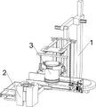
图1为本发明的第一种立体结构示意图;Fig. 1 is the first three-dimensional structure schematic diagram of the present invention;
图2为本发明的第二种立体结构示意图;2 is a schematic diagram of a second three-dimensional structure of the present invention;
图3为本发明的第三种立体结构示意图;3 is a schematic diagram of a third three-dimensional structure of the present invention;
图4为本发明移动系统的立体结构示意图;4 is a schematic three-dimensional structure diagram of the mobile system of the present invention;
图5为本发明保护部件拿取系统的第一种立体结构示意图;5 is a schematic diagram of the first three-dimensional structure of the protection component taking system of the present invention;
图6为本发明保护部件拿取系统的第二种立体结构示意图;6 is a schematic diagram of a second three-dimensional structure of the protection component taking system of the present invention;
图7为本发明保护部件拿取系统的第一种局部立体结构示意图;7 is a schematic diagram of a first partial three-dimensional structure of the protection component taking system of the present invention;
图8为本发明保护部件拿取系统的第二种局部立体结构示意图;8 is a schematic diagram of a second partial three-dimensional structure of the protection component taking system of the present invention;
图9为本发明保护部件拿取系统的第三种局部立体结构示意图;9 is a schematic diagram of a third partial three-dimensional structure of the protection component taking system of the present invention;
图10为本发明保护部件拿取系统的第四种局部立体结构示意图;10 is a schematic diagram of the fourth partial three-dimensional structure of the protection component taking system of the present invention;
图11为本发明核废料桶夹取系统的立体结构示意图;Figure 11 is a schematic three-dimensional structure diagram of the nuclear waste barrel clamping system of the present invention;
图12为本发明核废料桶夹取系统的第一种局部立体结构示意图;Figure 12 is a schematic diagram of the first partial three-dimensional structure of the nuclear waste barrel clamping system of the present invention;
图13为本发明核废料桶夹取系统的第二种局部立体结构示意图;Figure 13 is a schematic diagram of a second partial three-dimensional structure of the nuclear waste barrel clamping system of the present invention;
图14为本发明核废料桶夹取系统的第三种局部立体结构示意图;Figure 14 is a schematic diagram of the third partial three-dimensional structure of the nuclear waste barrel clamping system of the present invention;
图15为本发明的A区放大图。FIG. 15 is an enlarged view of area A of the present invention.
图中标号名称:1、移动系统,2、保护部件拿取系统,3、核废料桶夹取系统,101、第一电动转盘,102、连接块,103、电动提升轴,104、提升块,105、第一力臂,106、第一动力电机,107、第二力臂,108、第二动力电机,109、连接座,110、第三动力电机,111、第二电动转盘,112、第一连接板,201、第一连接架,202、驱动电机,203、第一传动轮,204、第二传动轮,205、第三传动轮,206、伸缩杆,207、第二连接板,208、第一电动推杆,209、第一锥齿轮,210、第二锥齿轮,211、第一丝杆,212、第一光杆,213、丝杆传动块,214、第二连接架,215、第二电动推杆,216、C型挡板,217、第一电动滑轨,218、第一电动滑块,219、第二电动滑块,220、第三电动推杆,221、第一插板,222、第四电动推杆,223、第二插板,224、第一夹块,225、中空板,226、第二夹块,227、第三插板,301、第四传动轮,302、转动杆,303、转动套,304、第一齿轮,305、第三连接板,306、第五电动推杆,307、第二齿轮,308、第二丝杆,309、第五传动轮,310、第二光杆,311、第一传动板,312、第六传动轮,313、第三丝杆,314、第三光杆,315、第二传动板,316、第三连接架,317、第四连接架,318、第六电动推杆,319、第四连接板,320、第四光杆,321、第二电动滑轨,322、第三电动滑块,323、第五连接板,324、第五连接架,325、第一弧形夹持块,326、第六连接板,327、第一弹簧传感器,328、第一压板,329、光线发射器,330、第四电动滑块,331、第七连接板,332、第六连接架,333、第八连接板,334、第二弹簧传感器,335、第二压板,336、接收器,337、第二弧形夹持块,338、模拟核废料桶。Label names in the figure: 1. Moving system, 2. Protecting parts picking system, 3. Nuclear waste barrel gripping system, 101, First electric turntable, 102, Connecting block, 103, Electric lifting shaft, 104, Lifting block, 105, the first force arm, 106, the first power motor, 107, the second force arm, 108, the second power motor, 109, the connecting seat, 110, the third power motor, 111, the second electric turntable, 112, the first A connecting plate, 201, a first connecting frame, 202, a drive motor, 203, a first transmission wheel, 204, a second transmission wheel, 205, a third transmission wheel, 206, a telescopic rod, 207, a second connection plate, 208 , the first electric push rod, 209, the first bevel gear, 210, the second bevel gear, 211, the first screw rod, 212, the first polished rod, 213, the screw drive block, 214, the second connecting frame, 215, The second electric push rod, 216, C-shaped baffle, 217, the first electric slide rail, 218, the first electric slider, 219, the second electric slider, 220, the third electric push rod, 221, the first plug plate, 222, fourth electric push rod, 223, second plug, 224, first clamp, 225, hollow plate, 226, second clamp, 227, third plug, 301, fourth drive wheel, 302, rotating rod, 303, rotating sleeve, 304, first gear, 305, third connecting plate, 306, fifth electric push rod, 307, second gear, 308, second screw, 309, fifth transmission wheel , 310, the second polished rod, 311, the first transmission plate, 312, the sixth transmission wheel, 313, the third screw, 314, the third polished rod, 315, the second transmission plate, 316, the third connecting frame, 317, Fourth connecting frame, 318, sixth electric push rod, 319, fourth connecting plate, 320, fourth polished rod, 321, second electric sliding rail, 322, third electric sliding block, 323, fifth connecting plate, 324 , the fifth connecting frame, 325, the first arc-shaped clamping block, 326, the sixth connecting plate, 327, the first spring sensor, 328, the first pressing plate, 329, the light emitter, 330, the fourth electric slider, 331, seventh connecting plate, 332, sixth connecting frame, 333, eighth connecting plate, 334, second spring sensor, 335, second pressing plate, 336, receiver, 337, second arc clamping block, 338 , Simulate nuclear waste barrels.
具体实施方式Detailed ways
以下结合具体实施例对上述方案做进一步说明。应理解,这些实施例是用于说明本申请而不限于限制本申请的范围。实施例中采用的实施条件可以根据具体厂家的条件做进一步调整,未注明的实施条件通常为常规实验中的条件。The above scheme will be further described below in conjunction with specific embodiments. It should be understood that these examples are intended to illustrate the present application and not to limit the scope of the present application. The implementation conditions used in the examples can be further adjusted according to the conditions of specific manufacturers, and the implementation conditions that are not specified are usually the conditions in routine experiments.
实施例1Example 1
一种多功能智能机械臂,如图1-15所示,包括有移动系统1、保护部件拿取系统2和核废料桶夹取系统3;移动系统1与保护部件拿取系统2相连接;保护部件拿取系统2与核废料桶夹取系统3相连接。A multi-functional intelligent robotic arm, as shown in Figure 1-15, includes a
在使用本多功能智能机械臂时,先将其固定在移动设备上,通过移动设备带动本多功能智能机械臂移动,对模拟核废料桶338进行操作,将本多功能智能机械臂的相应控制运行的部件安装在移动设备上或遥控设备上,工作时,通过移动系统1带动保护部件拿取系统2和核废料桶夹取系统3进行移动,保护部件拿取系统2拿取闭合在一起的第一夹块224和第二夹块226,核废料桶夹取系统3夹取模拟核废料桶338,通过保护部件拿取系统2和核废料桶夹取系统3相互配合将模拟核废料桶338平稳放置在需要堆放的地方,同时在其外表面包裹第一夹块224和第二夹块226,达到了可以适应多种工作环境,对模拟核废料桶338进行定位夹持,防止夹持时晃动,将模拟核废料桶338堆放在一起时,可以在其外表面包裹闭合的第一夹块224和第二夹块226,防止模拟核废料桶338受到磕碰,并提高堆放稳定性的效果。When using the multifunctional intelligent robotic arm, first fix it on the mobile device, drive the multifunctional intelligent robotic arm to move through the mobile device, operate the simulated
移动系统1包括有第一电动转盘101、连接块102、电动提升轴103、提升块104、第一力臂105、第一动力电机106、第二力臂107、第二动力电机108、连接座109、第三动力电机110、第二电动转盘111和第一连接板112;第一电动转盘101下方四角依次与四个连接块102进行固接;第一电动转盘101上方中部与电动提升轴103进行固接;电动提升轴103与提升块104进行滑动连接;提升块104与第一力臂105相连接;提升块104与第一动力电机106相连接,并且第一动力电机106输出轴与第一力臂105相连接;第一力臂105与第二力臂107相连接;第一力臂105与第二动力电机108相连接,并且第二动力电机108输出轴与第二力臂107相连接;第二力臂107与连接座109相连接;连接座109与第三动力电机110相连接,并且第三动力电机110与第二力臂107相连接;连接座109下方与第二电动转盘111进行固接;第二电动转盘111下方与第一连接板112进行固接,并且第一连接板112与保护部件拿取系统2相连接。The
在使用时,移动系统1带动保护部件拿取系统2和核废料桶夹取系统3移动,进而可将模拟核废料桶338转移到需要放置的地方,同时在其外面包裹有第一夹块224和第二夹块226,起保护作用,工作时,第一电动转盘101通电时,可带动电动提升轴103转动,电动提升轴103通电时,可带动提升块104上下移动,第一动力电机106通电时,可带动第一力臂105与提升块104之间发生偏转,第二动力电机108通电时,可带动第二力臂107与第一力臂105之间发生偏转,第三动力电机110通电时,可以连接座109与第二力臂107之间发生偏转,第二电动转盘111通电时,可带动第一连接板112转动,进而第一连接板112带动保护部件拿取系统2和核废料桶夹取系统3整体转动,相应部件相互配合,同时在外接的移动设备的辅助下,可以实现让保护部件拿取系统2和核废料桶夹取系统3在三维空间内自由移动,从而提高工作环境的适应能力。When in use, the moving
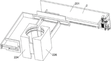
保护部件拿取系统2包括有第一连接架201、驱动电机202、第一传动轮203、第二传动轮204、第三传动轮205、伸缩杆206、第二连接板207、第一电动推杆208、第一锥齿轮209、第二锥齿轮210、第一丝杆211、第一光杆212、丝杆传动块213、第二连接架214、第二电动推杆215、C型挡板216、第一电动滑轨217、第一电动滑块218、第二电动滑块219、第三电动推杆220、第一插板221、第四电动推杆222、第二插板223、第一夹块224、中空板225、第二夹块226和第三插板227;第一连接架201与第一连接板112进行固接;第一连接架201与驱动电机202相连接;驱动电机202输出轴依次与第一传动轮203和第二传动轮204进行固接;第一传动轮203与核废料桶夹取系统3相连接;第二传动轮204外环面通过皮带与第三传动轮205进行传动连接;第三传动轮205与伸缩杆206进行固接,并且伸缩杆206与第一连接架201进行转动连接;伸缩杆206与第二连接板207进行转动连接;第二连接板207与第一电动推杆208进行固接,并且第一电动推杆208与第一连接架201进行固接;伸缩杆206与第一锥齿轮209进行固接;第一锥齿轮209侧面设置有第二锥齿轮210;第二锥齿轮210与第一丝杆211进行固接,并且第一丝杆211两侧均与第一连接架201进行转动连接;第一丝杆211侧面设置有第一光杆212,并且第一光杆212两侧均与第一连接架201进行固接;第一丝杆211外表面与丝杆传动块213进行传动连接,并且丝杆传动块213与第一光杆212进行滑动连接;丝杆传动块213与第二连接架214进行固接;第二连接架214与第二电动推杆215进行固接;第二电动推杆215与C型挡板216进行固接;第二连接架214与第一电动滑轨217进行固接;第一电动滑轨217依次与第一电动滑块218和第二电动滑块219进行滑动连接;第一电动滑块218与第三电动推杆220进行固接;第三电动推杆220与第一插板221进行固接;第二电动滑块219与第四电动推杆222进行固接;第四电动推杆222与第二插板223进行固接;第一插板221远离第一电动滑块218的一侧设置有第一夹块224;第一夹块224设置有一个供第一插板221插入的开槽;第一夹块224两侧分别与两组中空板225进行固接;第二插板223远离第二电动滑块219的一侧设置有第二夹块226;第二夹块226设置有一个供第二插板223插入的开槽;第二夹块226两侧分别与两组第三插板227进行固接。The protection component taking system 2 includes a first connecting frame 201, a driving motor 202, a first transmission wheel 203, a second transmission wheel 204, a third transmission wheel 205, a telescopic rod 206, a second connection plate 207, a first electric pusher Rod 208, first bevel gear 209, second bevel gear 210, first screw 211, first polished rod 212, screw transmission block 213, second connecting frame 214, second electric push rod 215, C-type baffle 216 , the first electric slide rail 217, the first electric slider 218, the second electric slider 219, the third electric push rod 220, the first plug board 221, the fourth electric push rod 222, the second plug board 223, the first plug The clamping block 224, the hollow plate 225, the second clamping block 226 and the third plug board 227; the first connecting frame 201 is fixedly connected with the first connecting plate 112; the first connecting frame 201 is connected with the driving motor 202; the driving motor 202 The output shaft is sequentially fixed with the first transmission wheel 203 and the second transmission wheel 204; the first transmission wheel 203 is connected with the nuclear waste barrel clamping system 3; the outer ring surface of the second transmission wheel 204 is connected to the third transmission wheel through a belt 205 for transmission connection; the third transmission wheel 205 is fixedly connected with the telescopic rod 206, and the telescopic rod 206 is rotationally connected with the first connecting frame 201; the telescopic rod 206 is rotationally connected with the second connecting plate 207; the second connecting plate 207 It is fixedly connected with the first electric push rod 208, and the first electric push rod 208 is fixed with the first connecting frame 201; the telescopic rod 206 is fixed with the first bevel gear 209; Two bevel gears 210; the second bevel gear 210 is fixedly connected with the first screw rod 211, and both sides of the first screw rod 211 are rotatably connected with the first connecting frame 201; the side of the first screw rod 211 is provided with a first polished rod 212, and both sides of the first polished rod 212 are fixed with the first connecting frame 201; the outer surface of the first screw rod 211 is connected with the screw rod transmission block 213, and the screw rod transmission block 213 slides with the first polished rod 212 connection; the screw drive block 213 is fixed with the second connecting frame 214; the second connecting frame 214 is fixed with the second electric push rod 215; the second electric push rod 215 is fixed with the C-type baffle 216; The second connecting frame 214 is fixedly connected with the first electric sliding rail 217; the first electric sliding rail 217 is slidably connected with the first electric sliding block 218 and the second electric sliding block 219 in turn; the first electric sliding block 218 is connected with the third electric sliding block 218 The push rod 220 is fixedly connected; the third electric push rod 220 is fixedly connected with the first plug board 221; the second electric slider 219 is fixed with the fourth electric push rod 222; the fourth electric push rod 222 is connected with the second plug The board 223 is fixed; the side of the first plug board 221 away from the first electric slider 218 is provided with a first clamping block 224; the first clamping block 224 is provided with a slot for the first plug board 221 to be inserted; Both sides of the clamping block 224 are respectively fixed with two sets of hollow plates 225 ; the second plug plate 223 is far away from the second electric slider 2 One side of the 19 is provided with a second clamping block 226; the second clamping block 226 is provided with a slot for the insertion of the second plug board 223; the two sides of the second clamping block 226 are respectively fixed with two sets of third plug boards 227. .
在使用时,首先人工将用来包裹模拟核废料桶338的第一夹块224和第二夹块226放置在保护部件拿取系统2可操作的范围内,通过移动系统1将保护部件拿取系统2移动到可对第一夹块224和第二夹块226拿取的位置,此时第一夹块224和第二夹块226相互闭合成一个整体,利于使用前的转移运输,工作时,第一插板221正对第一夹块224的开槽,同时第二插板223正对第二夹块226的开槽,随后第二电动推杆215带动C型挡板216移动,进而C型挡板216同时与第一夹块224和第二夹块226侧面接触,然后,第三电动推杆220和第四电动推杆222的推杆同时朝外部推,进而同时带动第一插板221和第二插板223移动,然后第一插板221插入第一夹块224的开槽中,同时第二插板223插入第二夹块226的开槽中,此时通过C型挡板216进行限位,防止插入时,第一夹块224和第二夹块226移动,进一步地,第一电动滑块218和第二电动滑块219同时在第一电动滑轨217内滑动,且移动的方向为朝彼此远离的方向移动,进而实现带动第一夹块224和第二夹块226朝两侧移动,使得原本闭合的两组中空板225和两组第三插板227分开,此时第一夹块224和第二夹块226彼此分离,进一步地,在核废料桶夹取系统3向下移动夹取模拟核废料桶338时,第一电动推杆208带动第二连接板207移动,进而让第一锥齿轮209和第二锥齿轮210彼此啮合,此时伸缩杆206被拉伸,随后,驱动电机202输出轴同时带动第一传动轮203和第二传动轮204转动,在第一传动轮203转动时,第一传动轮203可以给核废料桶夹取系统3提供动力,在第二传动轮204转动时,第二传动轮204外环面通过皮带带动第三传动轮205转动,第三传动轮205通过伸缩杆206带动第一锥齿轮209转动,进而第一锥齿轮209带动此时与其啮合的第二锥齿轮210转动,第二锥齿轮210带动第一丝杆211转动,随后第一丝杆211带动丝杆传动块213在水平方向移动,在此过程中,丝杆传动块213在第一光杆212外表面滑动导向,进而,丝杆传动块213移动带动第二连接架214移动,从而带动此时分离且被插入固定的第一夹块224和第二夹块226移动,进而将其移动到不影响核废料桶夹取系统3工作的位置,进一步地,在核废料桶夹取系统3成功夹取模拟核废料桶338后,第一夹块224和第二夹块226移动到模拟核废料桶338正下方,然后将模拟核废料桶338放置在第一夹块224和第二夹块226之间,随后保护部件拿取系统2工作让第一夹块224和第二夹块226再次闭合,从而包裹住模拟核废料桶338,此时模拟核废料桶338移动到需要用来存放的位置,此系统实现了可以自动拿取第一夹块224和第二夹块226,并配合核废料桶夹取系统3将第一夹块224和第二夹块226包裹在模拟核废料桶338外表面,从而保护模拟核废料桶338,使其在堆放时,可以更加稳定,同时防止相互碰撞。When in use, first manually place the
核废料桶夹取系统3包括有第四传动轮301、转动杆302、转动套303、第一齿轮304、第三连接板305、第五电动推杆306、第二齿轮307、第二丝杆308、第五传动轮309、第二光杆310、第一传动板311、第六传动轮312、第三丝杆313、第三光杆314、第二传动板315、第三连接架316、第四连接架317、第六电动推杆318、第四连接板319、第四光杆320、第二电动滑轨321、第三电动滑块322、第五连接板323、第五连接架324、第一弧形夹持块325、第六连接板326、第一弹簧传感器327、第一压板328、光线发射器329、第四电动滑块330、第七连接板331、第六连接架332、第八连接板333、第二弹簧传感器334、第二压板335、接收器336、第二弧形夹持块337和模拟核废料桶338;第四传动轮301外环面通过皮带与第一传动轮203进行传动连接;第四传动轮301与转动杆302进行固接,并且转动杆302与第一连接架201进行转动连接;转动杆302外表面与转动套303相连接;转动套303依次与第一齿轮304和第三连接板305相连接;第三连接板305与第五电动推杆306进行固接,并且第五电动推杆306与第一连接架201进行固接;第一齿轮304侧面设置有第二齿轮307;第二齿轮307与第二丝杆308进行固接;第二丝杆308与第五传动轮309进行固接;第二丝杆308外侧面设置有第二光杆310;第二丝杆308和第二光杆310均与第一传动板311相连接,并且第二丝杆308和第二光杆310均与第一连接架201相连接;第五传动轮309外环面通过皮带与第六传动轮312进行传动连接;第六传动轮312与第三丝杆313进行固接;第三丝杆313侧面设置有第三光杆314;第三丝杆313和第三光杆314均与第二传动板315相连接,并且第三丝杆313和第三光杆314与第一连接架201相连接;第三连接架316下方与第一连接架201进行螺栓连接,并且第三连接架316依次与第二光杆310、第二丝杆308、第三丝杆313和第三光杆314相连接;第一传动板311和第二传动板315依次与第四连接架317上方两侧进行螺栓连接;第四连接架317下方与第六电动推杆318进行固接;第六电动推杆318与第四连接板319进行固接;第四连接板319与第四光杆320进行滑动连接,并且第四光杆320与第四连接架317进行固接;第四连接板319下方与第二电动滑轨321进行固接;第二电动滑轨321依次与第三电动滑块322和第四电动滑块330进行滑动连接;第三电动滑块322与第五连接板323进行固接;第五连接板323与第五连接架324进行螺栓连接;第五连接架324与第一弧形夹持块325进行螺栓连接;第五连接架324下方与第六连接板326进行螺栓连接;第六连接板326侧面中部与第一弹簧传感器327进行固接;第一弹簧传感器327与第一压板328进行固接;第六连接板326依次与两组光线发射器329进行固接;第四电动滑块330与第七连接板331进行固接;第七连接板331与第六连接架332进行螺栓连接;第六连接架332下方与第八连接板333进行螺栓连接;第六连接架332与第二弧形夹持块337进行螺栓连接;第八连接板333侧面中部与第二弹簧传感器334进行固接;第二弹簧传感器334与第二压板335进行固接;第八连接板333依次与两组接收器336进行固接;两组光线发射器329依次与两组接收器336对应;第一弧形夹持块325和第二弧形夹持块337之间设置有模拟核废料桶338。The nuclear waste barrel clamping system 3 includes a fourth transmission wheel 301, a rotating rod 302, a rotating sleeve 303, a first gear 304, a third connecting plate 305, a fifth electric push rod 306, a second gear 307, and a second screw rod 308, the fifth transmission wheel 309, the second polished rod 310, the first transmission plate 311, the sixth transmission wheel 312, the third screw rod 313, the third polished rod 314, the second transmission plate 315, the third connecting frame 316, the fourth Connecting frame 317, sixth electric push rod 318, fourth connecting plate 319, fourth polished rod 320, second electric sliding rail 321, third electric sliding block 322, fifth connecting plate 323, fifth connecting frame 324, first Arc clamping block 325, sixth connecting plate 326, first spring sensor 327, first pressing plate 328, light emitter 329, fourth electric slider 330, seventh connecting plate 331, sixth connecting frame 332, eighth The connecting plate 333, the second spring sensor 334, the second pressing plate 335, the receiver 336, the second arc clamping block 337 and the simulated nuclear waste barrel 338; the outer ring surface of the fourth transmission wheel 301 is connected to the first transmission wheel 203 through the belt The transmission connection is carried out; the fourth transmission wheel 301 is fixedly connected with the rotating rod 302, and the rotating rod 302 is rotatably connected with the first connecting frame 201; the outer surface of the rotating rod 302 is connected with the rotating sleeve 303; The gear 304 is connected with the third connecting plate 305; the third connecting plate 305 is fixed with the fifth electric push rod 306, and the fifth electric push rod 306 is fixed with the first connecting frame 201; the side of the first gear 304 is arranged There is a second gear 307; the second gear 307 is fixed with the second screw rod 308; the second screw rod 308 is fixed with the fifth transmission wheel 309; the outer side of the second screw rod 308 is provided with a second polished rod 310; Both the second screw rod 308 and the second polished rod 310 are connected with the first transmission plate 311, and the second screw rod 308 and the second polished rod 310 are both connected with the first connecting frame 201; the outer ring surface of the fifth transmission wheel 309 passes through the belt The sixth transmission wheel 312 is fixedly connected with the third screw rod 313; the side of the third screw rod 313 is provided with a third polished rod 314; the third screw rod 313 and the third polished rod 314 are both connected with The second transmission plate 315 is connected, and the third screw rod 313 and the third polished rod 314 are connected with the first connecting frame 201; the lower part of the third connecting frame 316 is bolted with the first connecting frame 201, and the third connecting frame 316 Connect with the second polished rod 310, the second screw rod 308, the third screw rod 313 and the third polished rod 314 in sequence; the first transmission plate 311 and the second transmission plate 315 are bolted to the upper sides of the fourth connection frame 317 in sequence The fourth connecting frame 317 is fixed with the sixth electric push rod 318; the sixth electric push rod 318 is fixed with the fourth connecting plate 319; the fourth connecting plate 319 is slidably connected with the fourth polished rod 320, and the first Four polished rods 320 and fourth connecting frame 317 The bottom of the fourth connecting plate 319 is fixed with the second electric sliding rail 321; the second electric sliding rail 321 is slidably connected with the third electric sliding block 322 and the fourth electric sliding block 330 in turn; The block 322 is fixedly connected to the fifth connecting plate 323; the fifth connecting plate 323 is bolted to the fifth connecting frame 324; the fifth connecting frame 324 is bolted to the first arc-shaped clamping block 325; the fifth connecting frame 324 The bottom part is bolted to the sixth connecting plate 326; the middle part of the side surface of the sixth connecting plate 326 is fixed to the first spring sensor 327; the first spring sensor 327 is fixed to the first pressing plate 328; The group of light emitters 329 are fixed; the fourth electric slider 330 is fixed with the seventh connecting plate 331; the seventh connecting plate 331 is bolted with the sixth connecting frame 332; the bottom of the sixth connecting frame 332 is connected with the eighth connection The plate 333 is bolted; the sixth connecting frame 332 is bolted to the second arc-shaped clamping block 337; the middle part of the side surface of the eighth connecting plate 333 is fixed to the second spring sensor 334; the second spring sensor 334 is connected to the second pressure plate 335 are fixed; the eighth connecting plate 333 is fixed with the two sets of receivers 336 in sequence; the two sets of light emitters 329 correspond to the two sets of receivers 336 in sequence; A simulated nuclear waste barrel 338 is arranged between the holding blocks 337 .
在使用时,首先核废料桶夹取系统3移动到需要模拟核废料桶338上方,工作时,第一传动轮203外环面通过皮带带动第四传动轮301转动,进一步地,第五电动推杆306通过第三连接板305带动转动套303移动,使得第一齿轮304与第二齿轮307彼此啮合,随后第四传动轮301通过转动杆302带动转动套303转动,转动套303带动第一齿轮304转动,第一齿轮304带动此时与其啮合的第二齿轮307转动,第二齿轮307带动第二丝杆308转动,同时第五传动轮309也会被带动转动,进而第二丝杆308带动第一传动板311向下移动,此时第一传动板311在第二光杆310外表面滑动进行导向,与此同时,第五传动轮309外环面通过皮带带动第六传动轮312转动,第六传动轮312带动第三丝杆313转动,进而第三丝杆313带动第二传动板315向下移动,此时第二传动板315在第三光杆314外表面滑动进行导向,如此实现第一传动板311和第二传动板315带动第四连接架317向下移动,进而可以带动第一弧形夹持块325和第二弧形夹持块337向下移动,并与模拟核废料桶338上方的凸起高度一致,随后第三电动滑块322和第四电动滑块330在第二电动滑轨321中滑动,并且移动方向为朝彼此靠近的方向,进而第三电动滑块322通过第五连接板323带动第五连接架324移动,随后带动第一弧形夹持块325移动,同时第四电动滑块330通过第七连接板331带动第六连接架332移动,从而带动第二弧形夹持块337移动,如此实现第一弧形夹持块325和第二弧形夹持块337夹住模拟核废料桶338,从而实现对模拟核废料桶338的稳定夹持,进一步地,在第一弧形夹持块325和第二弧形夹持块337将模拟核废料桶338完全夹持之前,需要进行定位,在此过程中,两组光线发射器329发出光线,然后两组接收器336接收,两组光线发射器329之间的距离为模拟核废料桶338直径,进而在两组接收器336都接收到光线时,模拟核废料桶338恰好位于第一弧形夹持块325和第二弧形夹持块337的中心点连线上,否则,通过第六电动推杆318带动第四连接板319移动,进而第四连接板319带动第二电动滑轨321移动,从而实现带动第一弧形夹持块325和第二弧形夹持块337移动,此时第四连接板319在第四光杆320外表面滑动,进一步地,在第三电动滑块322和第四电动滑块330在第二电动滑轨321中滑动时,第一压板328和第二压板335与模拟核废料桶338外表面接触,进而分别压缩第一弹簧传感器327和第二弹簧传感器334,在此过程中,第一弹簧传感器327和第二弹簧传感器334检测出各自的受力情况,进而控制第二电动滑轨321和第四电动滑块330在第二电动滑轨321中移动的距离,使得第一弹簧传感器327和第二弹簧传感器334两者受力一致,进而实现第一弧形夹持块325和第二弧形夹持块337对模拟核废料桶338精确夹取,可以防止模拟核废料桶338发生晃动,进而引发事故,进一步地,在第一弧形夹持块325和第二弧形夹持块337夹紧模拟核废料桶338后,通过第二电动滑轨321带动第三电动滑块322和第四电动滑块330整体移动,使得模拟核废料桶338位于第二电动滑轨321正下方,进一步地,通过驱动电机202反向转动,让模拟核废料桶338向上移动,随后保护部件拿取系统2带动第一夹块224和第二夹块226移动到模拟核废料桶338正下方,然后通过外接的移动设备和移动系统1将第一夹块224和第二夹块226移动到模拟核废料桶338需要放置的地方,然后模拟核废料桶338再次向下移动并移动到第一夹块224和第二夹块226之间,之后核废料桶夹取系统3松开模拟核废料桶338,并将第一夹块224和第二夹块226包裹在模拟核废料桶338外表面,从而完成模拟核废料桶338的堆放工作,此系统实现了可以精准定位模拟核废料桶338,并对其稳固夹持,配合保护部件拿取系统2完成对模拟核废料桶338堆放工作。When in use, firstly, the nuclear waste
第一夹块224和第二夹块226相互靠近的一侧上方设置有两组开槽,并且下方也设置有两组开槽,第一夹块224和第二夹块226闭合时,形成的空间与模拟核废料桶338大小相同。Two sets of slots are provided on the side where the
有利于更好的包裹住模拟核废料桶338。It is beneficial to better wrap the simulated
两组第三插板227的两侧均设置有四个凸起。Four protrusions are provided on both sides of the two sets of
可以让第一夹块224和第二夹块226闭合的更紧。The
第六电动推杆318、第四连接板319和第四光杆320均设置有两组,呈对称分布在第四连接架317下方两侧。There are two groups of the sixth
配合工作,实现第二电动滑轨321的平稳移动。Working together, the second
第一弧形夹持块325和第二弧形夹持块337相互靠近的一侧均设置有两组弧形凹槽,模拟核废料桶338外表面上方设置有两组凸起,并且外表面下方也设置有两组凸起。The sides of the first arc-shaped
可以实现更稳定的夹持。More stable clamping can be achieved.
上述实施例,只是本发明的较佳实施例,并非用来限制本发明实施范围,故凡以本发明权利要求所述内容所做的等效变化,均应包括在本发明权利要求范围之内。The above-mentioned embodiments are only preferred embodiments of the present invention, and are not intended to limit the scope of implementation of the present invention. Therefore, all equivalent changes made based on the contents described in the claims of the present invention shall be included within the scope of the claims of the present invention. .
Claims (6)
Priority Applications (1)
| Application Number | Priority Date | Filing Date | Title |
|---|---|---|---|
| CN202110411300.9A CN113059552B (en) | 2021-04-16 | 2021-04-16 | Multifunctional intelligent mechanical arm |
Applications Claiming Priority (1)
| Application Number | Priority Date | Filing Date | Title |
|---|---|---|---|
| CN202110411300.9A CN113059552B (en) | 2021-04-16 | 2021-04-16 | Multifunctional intelligent mechanical arm |
Publications (2)
| Publication Number | Publication Date |
|---|---|
| CN113059552A CN113059552A (en) | 2021-07-02 |
| CN113059552B true CN113059552B (en) | 2022-04-26 |
Family
ID=76566904
Family Applications (1)
| Application Number | Title | Priority Date | Filing Date |
|---|---|---|---|
| CN202110411300.9A Active CN113059552B (en) | 2021-04-16 | 2021-04-16 | Multifunctional intelligent mechanical arm |
Country Status (1)
| Country | Link |
|---|---|
| CN (1) | CN113059552B (en) |
Families Citing this family (3)
| Publication number | Priority date | Publication date | Assignee | Title |
|---|---|---|---|---|
| CN113928849B (en) * | 2021-11-06 | 2023-05-05 | 广东汇雄实业投资有限公司 | Chemical dangerous goods clamping device for safety production |
| CN114750140A (en) * | 2022-03-02 | 2022-07-15 | 陈威 | Manipulator for grabbing and quantitatively discharging liquid material barrel |
| CN115923093B (en) * | 2022-11-16 | 2023-11-03 | 佛山市南海功成塑料有限公司 | Plastic bottle blow molding production equipment and plastic bottle blow molding method |
Citations (3)
| Publication number | Priority date | Publication date | Assignee | Title |
|---|---|---|---|---|
| CN108818597A (en) * | 2018-08-25 | 2018-11-16 | 陈明亮 | A kind of column lithium ion battery is intelligent to clamp system and its clamping processing method |
| CN109015594A (en) * | 2018-10-08 | 2018-12-18 | 李友朋 | Industrial robot |
| CN111736197A (en) * | 2020-03-09 | 2020-10-02 | 上海交通大学 | A device for detecting the surface dose rate of a low and medium level radioactive waste barrel and its application |
Family Cites Families (1)
| Publication number | Priority date | Publication date | Assignee | Title |
|---|---|---|---|---|
| CN108436897B (en) * | 2018-06-14 | 2018-11-27 | 象山浩力信息科技有限公司 | A kind of industrial robot device |
-
2021
- 2021-04-16 CN CN202110411300.9A patent/CN113059552B/en active Active
Patent Citations (3)
| Publication number | Priority date | Publication date | Assignee | Title |
|---|---|---|---|---|
| CN108818597A (en) * | 2018-08-25 | 2018-11-16 | 陈明亮 | A kind of column lithium ion battery is intelligent to clamp system and its clamping processing method |
| CN109015594A (en) * | 2018-10-08 | 2018-12-18 | 李友朋 | Industrial robot |
| CN111736197A (en) * | 2020-03-09 | 2020-10-02 | 上海交通大学 | A device for detecting the surface dose rate of a low and medium level radioactive waste barrel and its application |
Also Published As
| Publication number | Publication date |
|---|---|
| CN113059552A (en) | 2021-07-02 |
Similar Documents
| Publication | Publication Date | Title |
|---|---|---|
| CN113059552B (en) | Multifunctional intelligent mechanical arm | |
| CN207142319U (en) | A kind of pallet automatic charging & discharging machine | |
| CN115365332A (en) | An intelligent bending equipment for plates | |
| CN110950076B (en) | Top rotation type composite sheet storage device | |
| CN108328273A (en) | Battery modules switching mechanism and its full-automatic module group assembling stacking machine | |
| CN112713027B (en) | Full-automatic intelligent manufacturing process for intelligent power switch button cap | |
| CN221234789U (en) | Sheet layering feeding equipment | |
| CN218806780U (en) | High-throughput biological reagent automatic filling machine | |
| CN220222700U (en) | Electric fitting stacking device | |
| CN208669051U (en) | A kind of underground Multi-storey up-down & translation stereo garage | |
| CN217943375U (en) | Clamping device for carrying industrial robot | |
| CN217437129U (en) | Solar glass placing equipment with stacking function | |
| CN116923143A (en) | Portable new energy automobile battery charging outfit | |
| CN219258483U (en) | Logistics storage robot | |
| CN206516718U (en) | Laminating machine | |
| CN214495586U (en) | Quick elevating gear of electricity liquid push rod driven | |
| CN212695432U (en) | Material moving structure for machining end of high-voltage-resistant connecting wire of new energy automobile | |
| CN212050357U (en) | Lifting device for stereoscopic warehouse | |
| CN221776725U (en) | A cargo handling equipment for a three-dimensional warehouse | |
| CN209626339U (en) | A kind of battery pack brush tab and enter casing equipment | |
| CN217349875U (en) | Automatic barreled water stacking machine | |
| CN214058071U (en) | Facial mask packagine machine and extracting device thereof | |
| CN112373780A (en) | Packing device for sequentially packing paper case | |
| CN219469035U (en) | Intelligent stacking device | |
| CN219384665U (en) | A mobile device for container stacking machine |
Legal Events
| Date | Code | Title | Description |
|---|---|---|---|
| PB01 | Publication | ||
| PB01 | Publication | ||
| SE01 | Entry into force of request for substantive examination | ||
| SE01 | Entry into force of request for substantive examination | ||
| GR01 | Patent grant | ||
| GR01 | Patent grant |