CN112975548B - Cutting fluid treatment device and method applied to machine tool - Google Patents
Cutting fluid treatment device and method applied to machine tool Download PDFInfo
- Publication number
- CN112975548B CN112975548B CN202110204360.3A CN202110204360A CN112975548B CN 112975548 B CN112975548 B CN 112975548B CN 202110204360 A CN202110204360 A CN 202110204360A CN 112975548 B CN112975548 B CN 112975548B
- Authority
- CN
- China
- Prior art keywords
- cutting
- plate
- machine tool
- fixedly arranged
- filtering
- Prior art date
- Legal status (The legal status is an assumption and is not a legal conclusion. Google has not performed a legal analysis and makes no representation as to the accuracy of the status listed.)
- Active
Links
Images



Classifications
-
- B—PERFORMING OPERATIONS; TRANSPORTING
- B23—MACHINE TOOLS; METAL-WORKING NOT OTHERWISE PROVIDED FOR
- B23Q—DETAILS, COMPONENTS, OR ACCESSORIES FOR MACHINE TOOLS, e.g. ARRANGEMENTS FOR COPYING OR CONTROLLING; MACHINE TOOLS IN GENERAL CHARACTERISED BY THE CONSTRUCTION OF PARTICULAR DETAILS OR COMPONENTS; COMBINATIONS OR ASSOCIATIONS OF METAL-WORKING MACHINES, NOT DIRECTED TO A PARTICULAR RESULT
- B23Q11/00—Accessories fitted to machine tools for keeping tools or parts of the machine in good working condition or for cooling work; Safety devices specially combined with or arranged in, or specially adapted for use in connection with, machine tools
- B23Q11/10—Arrangements for cooling or lubricating tools or work
- B23Q11/1069—Filtration systems specially adapted for cutting liquids
-
- B—PERFORMING OPERATIONS; TRANSPORTING
- B23—MACHINE TOOLS; METAL-WORKING NOT OTHERWISE PROVIDED FOR
- B23Q—DETAILS, COMPONENTS, OR ACCESSORIES FOR MACHINE TOOLS, e.g. ARRANGEMENTS FOR COPYING OR CONTROLLING; MACHINE TOOLS IN GENERAL CHARACTERISED BY THE CONSTRUCTION OF PARTICULAR DETAILS OR COMPONENTS; COMBINATIONS OR ASSOCIATIONS OF METAL-WORKING MACHINES, NOT DIRECTED TO A PARTICULAR RESULT
- B23Q11/00—Accessories fitted to machine tools for keeping tools or parts of the machine in good working condition or for cooling work; Safety devices specially combined with or arranged in, or specially adapted for use in connection with, machine tools
- B23Q11/10—Arrangements for cooling or lubricating tools or work
Landscapes
- Engineering & Computer Science (AREA)
- Mechanical Engineering (AREA)
- Grinding-Machine Dressing And Accessory Apparatuses (AREA)
Abstract
The invention discloses a cutting fluid processing device applied to a machine tool and a processing method thereof, wherein the device comprises: the device comprises a diversion trench assembly fixedly arranged on a machine tool, a filtering device fixedly arranged at the bottom of the diversion trench assembly and simultaneously arranged below the machine tool, and a spraying device embedded in cutting equipment of the machine tool; the filtering device includes: the first filtering device is rotatably arranged at the bottom of the collecting cover; the second filtering device is positioned at the bottom of the first filtering device; and a recovery pipeline fixedly arranged at the bottom of the second filtering device. The guide chute assembly can collect the cutting waste liquid dropping on the cutting workbench, coarse waste residues and waste residue particles in the cutting waste liquid are filtered and adsorbed in the filtering device after being collected, and turbidity monitoring is carried out on the filtered cutting liquid through the recovery pipeline, so that damage to a liquid supply pipe diameter and a pump body caused by the fact that the filtering device breaks down and the recovery liquid with excessive impurities is avoided.
Description
Technical Field
The invention belongs to the field of precision machining manufacturing equipment, and particularly relates to a cutting fluid treatment device and a treatment method applied to a machine tool.
Background
After the cutting fluid is put into use, a large amount of cutting chips are mixed in the cutting fluid, and the size and the shape of the cutting chips are different, so that filter meshes are easily blocked by the existing filtering device, and the recycling of the cutting fluid is influenced; secondly, the blocked cutting debris is easy to scratch the wall of the filtering device and the circulating pipeline, so that the cutting fluid cannot be recycled.
Disclosure of Invention
The purpose of the invention is as follows: provides a cutting fluid processing device and a processing method applied to a machine tool, which are used for solving the problems in the prior art.
The technical scheme is as follows: a cutting fluid treatment apparatus for use in a machine tool, comprising:
the device comprises a diversion trench assembly fixedly arranged on a machine tool, a filtering device fixedly arranged at the bottom of the diversion trench assembly and simultaneously arranged below the machine tool, a spraying device embedded in cutting equipment of the machine tool, and a camera shooting mechanism fixedly arranged above the machine tool.
In a further embodiment, the flow leader assembly comprises: the guide plate is symmetrically arranged below the edge of the cutting workbench, the two guide grooves are fixedly arranged at the edge of the cutting workbench and correspond to the guide plate, and the lifting device is fixedly arranged at the bottom of the guide plate; and the bottoms of the two diversion trenches are provided with discharge pipes communicated with the filtering device.
In a further embodiment, the guide plate abuts against the edge of the workbench, and an arc-shaped cover is integrally connected to one end far away from the edge, and the height of the arc-shaped cover exceeds the edge of the workbench; the baffle includes: the flexible metal plate comprises a first bottom plate, a second bottom plate, a hinge assembly and a flexible metal plate, wherein the first bottom plate is hinged to one end of a machine tool, the second bottom plate is hinged to the other end of the machine tool and is positioned on the same horizontal line with the first bottom plate, the hinge assembly is connected between the first bottom plate and the second bottom plate, and the flexible metal plate covers and is fixed on the first bottom plate, the second bottom plate and the hinge assembly; one side of the hinge assembly is fixedly connected with the lifting device;
the lifting device is a micro hydraulic assembly fixedly mounted on a machine tool, a power output rod of the micro hydraulic assembly is fixedly connected with the hinge assembly and then drives the hinge assembly to move up and down, the hinge assembly enables a first bottom plate and a second bottom plate hinged to two sides to synchronously rotate around the machine tool while moving up and down, and then the guide plate forms two wedge surfaces relative to the guide grooves on the two sides during flow guiding, so that the flow speed of cutting fluid on the flexible metal plate is accelerated.
In a further embodiment, the filter device comprises: the first filtering device is rotatably arranged at the bottom of the collecting cover; the second filtering device is positioned at the bottom of the first filtering device; and a recovery pipeline fixedly arranged at the bottom of the second filtering device.
In a further embodiment, the first filtering device comprises: the bearing seats are fixedly arranged on two sides of the collecting cover; the slag collecting device comprises a rotating shaft inserted on two bearing blocks, a connecting cylinder fixedly arranged on the rotating shaft, a driving device arranged on one side of the rotating shaft in a transmission manner, and a slag collecting groove integrally connected to a collecting cover and positioned on one side below the connecting cylinder, wherein a through opening is formed in the outer part of the slag collecting groove; the top fixed mounting of opening is sealed, the inside in collection sediment groove is provided with takes out the core, take out the core and be embedded to have a weight sensor, take out the core and can take out from the opening.
In a further embodiment, a plurality of filter plates are inserted into the connecting cylinder; the filter plate is provided with filter meshes; the driving device includes: the setting is at the driving motor who collects the cover outside, and fixed mounting is at the drive gear of driving motor power take off end to and cup joint the driving chain on drive gear, the other end of driving chain cup joints in the pivot, driving motor's power is rotatory on the bearing frame through driving chain drive shaft, and then the connecting cylinder is rotatory, thereby makes the filter topple over the board of taking out in the collection sediment groove with the large granule residue that filters out when filtering cutting fluid.
In a further embodiment, a drawing device is further arranged outside the slag collecting groove, and the drawing device comprises: the slide rail of fixed mounting in collection slag chute bottom portion, the fixed rack that sets up in board top one side of loosing core rotates the driven gear who installs in rack one side, driven gear's center department grafting transmission shaft, the power take off end at driving motor is connected in the other end transmission of transmission shaft, and then driving motor's power passes through the transmission shaft and drives driven gear, the rack motion of screwing in driven gear one side and then making the board of loosing core move on the slide rail when driven gear is rotatory, can follow sealed the roll-off in the lid automatically when opening sealed lid.
In a further embodiment, the second filtering means comprises: the magnetic adsorption plate is fixedly arranged at the bottom of the collecting cover, the diaphragm filter plate is arranged on one side of the magnetic adsorption plate, and the recovery pipeline is fixedly arranged on one side of the diaphragm filter plate.
In a further embodiment, the recovery conduit communicates with the cutting fluid injection device through a conduit assembly comprising: the system comprises a first liquid supply pump communicated with a recovery pipeline, a liquid supply pipe communicated with a liquid outlet of the liquid supply pump, a three-way valve fixedly arranged at the other end of the liquid supply pipe, and a turbidity measuring meter fixedly arranged in the liquid supply pipe; the outlet end of the three-way valve is respectively and fixedly connected with the first branch pipe and the second branch pipe for communication; the other end of the first branch pipe is communicated with a high-pressure pipe of the cutting fluid injection device, and the second branch pipe is communicated with the collection cover through a second fluid supply pump.
In a further embodiment, the following working steps are included:
in the cutting process, the used cutting fluid carries cutting residues and enters the collecting cover from the edge of the workbench and then the guide plate through the guide groove at one end of the guide plate;
after cutting is finished, the camera mechanism detects residual large residues or accumulated residue piles in the workbench, the injection device is started to inject the large residues and the residue piles into the guide plate, and then the lifting device is started, the guide plate forms two wedge surfaces relative to the guide grooves on the two sides during flow guide, so that the flow rate of cutting fluid on the flexible metal plate is accelerated; the spray gun device is started to assist in cleaning the diversion trench; metal impurities are prevented from being remained and accumulated in the guide plate and the guide groove;
the cutting waste liquid entering the collecting cover passes through the first filtering device, when a driving motor in the first filtering device operates, the power of the driving motor drives a rotating shaft to rotate on a bearing seat through a transmission chain, and then a connecting cylinder rotates, so that a filtering plate filters the cutting liquid and pours large-particle filtered residues onto a core-pulling plate in a residue collecting groove;
filtering the filtered cutting waste liquid again, and performing magnetic attraction and diaphragm filtration on the metal dust remained in the cutting waste liquid through a second filtering device so as to convey the metal dust into a recovery pipeline;
a turbidity measuring meter in the recovery pipeline measures the recovery liquid, and then sends a detection result to a controller, the controller evaluates the quality of the recovery liquid, and controls a three-way valve to communicate a liquid supply pipe and a first branch pipe after the use standard is reached, so that the first branch pipe provides supply for an injection device in the cutting equipment;
the controller is used for reminding maintenance personnel to overhaul the filtering equipment when the evaluation result of the recovered liquid does not meet the use standard; after the filter equipment is replaced, the three-way valve is controlled to be communicated with the liquid supply pipe and the second branch pipe, so that the cutting liquid flowing into the recovery pipeline is extracted by the second branch pipe and enters the collection cover to enter the filtering process again.
Has the advantages that: the invention has the following advantages:
1. the water conservancy diversion groove subassembly can be collected the cutting waste liquid that drops on cutting workstation and then, can carry out unified collection and retrieve to the cutting waste liquid.
2. Go into through first filter equipment among the filter equipment and second filter equipment to the thick waste residue and the waste residue granule in the cutting waste liquid and filter and adsorb, filter among the first filter equipment rotates and then forms the circulation and emptys and filterable process in collecting the cover under the drive of connecting cylinder, the thick waste residue that filters out emptys on the board of taking out of below through the inertia of rotatory in-process, through in the automatic discharge filter equipment of pull device, tentatively screen out thick waste residue, and then reduce thick waste residue and block up the absorption and the piling up that influence thin waste residue granule to second filter equipment.
3. The recovered cutting fluid is collected and monitored through the recovery pipeline, and the situation that metal particles enter the injection device to block a spray head and a pump body in a pipeline after the filter device is damaged is avoided.
Drawings
FIG. 1 is a schematic view showing the mounting of a cutting fluid treatment apparatus of the present invention on a machine tool.
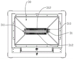
Fig. 2 is a schematic view of the structure of the first filtering means and the collecting cover of the present invention.
Fig. 3 is a schematic structural view of the driving device of the present invention.
Fig. 4 is a schematic view of the construction of the drawer according to the invention.
Fig. 5 is a schematic view of the structure of a second filter device according to the present invention.
FIG. 6 is a schematic view of the construction of the recovery pipeline of the present invention.
The reference signs are: the device comprises a machine tool 1, a diversion trench assembly 2, a diversion plate 20, a first bottom plate 200, a second bottom plate 201, a hinge assembly 202, a diversion trench 21, a micro hydraulic assembly 22, a discharge pipe 23, a filtering device 3, a collecting cover 30, a first filtering device 311, a bearing seat 310, a rotating shaft 311, a connecting cylinder 312, a filtering plate 3120, a driving device 313, a driving motor 3130, a transmission chain 3131, a transmission gear 3132, a slag collecting groove 314, a core-pulling plate 315, a first filtering device 322, a magnetic adsorption plate 320, a membrane filtering plate 321, a recovery pipeline 322, a first liquid supply pump 3220, a liquid supply pipe 3221, a three-way valve 3222, a first branch pipe 3223, a second branch pipe 3224, a drawing device 34, a sliding rail 340, a rack 341, a driven gear 342, a driving motor 343, a spraying device 4 and a camera shooting mechanism 5.
Detailed Description
In the following description, numerous specific details are set forth in order to provide a more thorough understanding of the present invention. It will be apparent, however, to one skilled in the art, that the present invention may be practiced without one or more of these specific details. In other instances, well-known features have not been described in order to avoid obscuring the invention.
The applicant finds that after the cutting fluid is put into use, a large amount of cutting chips are mixed in the cutting fluid, and the size and the shape of the cutting chips are different, and the cutting chips are easy to block a filter mesh after passing through the conventional filter device, so that the recycling of the cutting fluid is influenced; secondly, the blocked cutting debris is easy to scratch the wall of the filtering device and the circulating pipeline, so that the cutting fluid cannot be recycled.
A cutting fluid treatment apparatus applied to a machine tool as shown in fig. 1 to 6 includes: the device comprises a guide groove component 2, a guide plate 20, a first bottom plate 200, a second bottom plate 201, a hinge component 202, a guide groove 21, a micro hydraulic component 22, a discharge pipe 23, a filter device 3, a collection cover 30, a first filter device 311, a bearing seat 310, a rotating shaft 311, a connecting cylinder 312, a filter plate 3120, a driving device 313, a driving motor 3130, a transmission chain 3131, a transmission gear 3132, a slag collection groove 314, a core-pulling plate 315, a first filter device 322, a magnetic adsorption plate 320, a membrane filter plate 321, a recovery pipeline 322, a first liquid supply pump 3220, a liquid supply pipe 3221, a three-way valve 3222, a first branch pipe 3223, a second branch pipe 3224, a drawing device 34, a sliding rail 340, a rack 341, a driven gear 342, a driving motor 343, a spraying device 4 and a camera shooting mechanism 5.
The guide groove 21 assembly 2 is fixedly arranged on the machine tool 1 and can collect and guide cutting fluid used on the machine tool 1; the filtering device 3 is fixedly arranged at the bottom of the diversion trench 21 component 2 and is arranged below the machine tool 1 at the same time, and can filter the cutting waste liquid guided by the diversion trench 21 component 2; the injection device 4 is embedded in the cutting equipment of the machine tool 1 and can move synchronously along with the cutting tool so as to cool the cutting tool, and the camera mechanism 5 is fixedly installed above the machine tool 1 and can monitor the machining data of the machine tool 1 and the residual chips machined by the machine tool 1.
The existing diversion trench 21 assembly 2 can only play a basic diversion and collection role, and when cutting chips on the machine tool 1 are cleaned, cutting fluid can only be continuously sprayed by the spraying device 4, so that the chips on the machine tool 1 enter the diversion trench 21 assembly 2 along with high-pressure fluid, and the cleaning effect on the machine tool 1 is achieved, but the cutting fluid is greatly wasted in the process, so that the diversion trench 21 assembly 2 which can be used for collecting and diverting waste residues and waste liquid at the same time in an accelerated manner can be used for reducing the waste of the cutting fluid; the diversion trench 21 assembly 2 comprises: the guide plates 20 are symmetrically arranged below the edge of the cutting workbench, the guide plates 20 are fixedly arranged at the edge of the cutting workbench and are arranged in the two guide grooves 21 corresponding to the guide plates 20, and the lifting devices are fixedly arranged at the bottom of the guide plates 20; the bottom of the two diversion trenches 21 is provided with a discharge pipe 23 communicated with the filter device 3, and the discharge of waste liquid and waste residue can be accelerated by matching with an air gun.
The guide plate 20 is abutted against the edge of the workbench, and an arc-shaped cover is integrally connected to one end far away from the edge, and the height of the arc-shaped cover exceeds that of the edge of the workbench; the arc-shaped hood can prevent collected waste liquid from overflowing the guide plate 20. The baffle 20 includes: the machine tool comprises a first base plate 200 hinged at one end of the machine tool 1, a second base plate 201 hinged at the other end of the machine tool 1 and positioned on the same horizontal line with the first base plate 200, a hinge assembly 202 connected between the first base plate 200 and the second base plate 201, and a flexible metal plate covering and fixed on the first base plate 200, the second base plate 201 and the hinge assembly 202; the integrally formed structure can be bent along with the rotation of the first bottom plate 200 and the second bottom plate 201 to form a seamless flow guide slope surface; one side of the hinge assembly 202 is fixedly connected with a lifting device; the lifting device is a miniature hydraulic assembly 22 fixedly mounted on the machine tool 1, a power output rod of the miniature hydraulic assembly 22 is fixedly connected with the hinge assembly 202 to further drive the hinge assembly 202 to move up and down, the hinge assembly 202 enables the first bottom plate 200 and the second bottom plate 201 hinged to the two sides to synchronously rotate around the machine tool 1 while moving up and down, and then the guide plate 20 forms two wedge surfaces relative to the guide grooves 21 on the two sides during flow guide, so that the flow rate of cutting fluid on the flexible metal plate is accelerated. Thereby eliminating the residual debris on the machine tool 1 and saving the use of the cutting fluid.
The existing filtering device 3 usually adopts a filtering device 3 with single function, and a large amount of suspended particles still remain in the filtered cutting fluid to influence the quality of the filtered waste fluid; the problem that coarse particles and micro particles can not be filtered in a double-layered mode by the conventional filtering device 3 is solved, so that the filtering device 3 is frequently blocked by mixed coarse and fine particles, and high cleaning rate and maintenance rate of a filtering filter element are further caused; filter device 3 in the present invention: a collecting cover 30 communicated with the other end of the discharge pipe 23, and a first filtering device 31 rotatably installed at the bottom of the collecting cover 30; a first filter unit 32 located at the bottom of the first filter unit 31; and a recovery pipe 322 fixedly installed at the bottom of the first filtering device 32. Go into through the coarse waste residue and the waste residue granule of first filter equipment 31 and first filter equipment 32 in filter equipment 3 in to the cutting waste liquid and filter and adsorb, filter 3120 in first filter equipment 31 rotates and then forms the circulation and emptys and filterable process in collecting cover 30 under the drive of connecting cylinder 312, the coarse waste residue that filters out emptys on the board 315 of taking out of below through the inertia of rotatory in-process, in the automatic filter equipment 3 that discharges of pull device 34, tentatively screen out coarse waste residue, and then reduce coarse waste residue and block up the absorption and the piling up that influence fine waste residue granule to first filter equipment 32.
The first filter device 31 includes: bearing seats 310 fixedly installed at both sides of the collecting cover 30; the slag collecting device comprises a rotating shaft 311 inserted in the two bearing blocks 310, a connecting cylinder 312 fixedly installed on the rotating shaft 311, a driving device 313 installed on one side of the rotating shaft 311 in a transmission manner, and a slag collecting groove 314 integrally connected to the collecting cover 30 and located on one side below the connecting cylinder 312, wherein a through opening is formed in the outer part of the slag collecting groove 314; the sealed lid of top fixed mounting of opening, the inside of collection sediment groove 314 is provided with takes out the core board 315, take out embedded weight sensor in the core board 315, take out the core board 315 and can take out from the opening.
Further, a plurality of filter plates 3120 are inserted into the connecting cylinder 312; the filter plate 3120 is provided with a filter mesh; the driving device 313 includes: the filter plate cleaning machine comprises a driving motor 3130 arranged outside a collecting cover 30, a transmission gear 3132 fixedly arranged at the power output end of the driving motor 3130, and a transmission chain 3131 sleeved on the transmission gear 3132, wherein the other end of the transmission chain 3131 is sleeved on a rotating shaft 311, the power of the driving motor 3130 drives the rotating shaft 311 to rotate on a bearing seat 310 through the transmission chain 3131, and then a connecting cylinder 312 rotates, so that a filter plate 3120 filters cutting fluid and pours filtered large-particle residues onto a core pulling plate 315 in a residue collecting groove 314 on one side below the filter plate 3120, further, the circular filtering effect of coarse particles at the inlet of the collecting cover 30 can be realized, the filtered coarse particles can be automatically poured onto the core pulling plate 315 through inertia generated in the rotating process, the later-stage cleaning is convenient, further, the automatic cleaning process can be carried out by a plurality of filter plates 3120, the technical problem that the filter screen plate needs to be detached and cleaned due to blockage of the coarse particles is avoided, but also can be matched with the drawing device 34 to realize the automatic guiding-out process of the coarse filter residue.
Further, the drawing device 34 is fixedly installed outside the slag collecting groove 314, and can act on the core-pulling plate 315 to enable the core-pulling plate 315 to draw and pull in the slag collecting groove 314 in a reciprocating manner, so that the function of automatically dumping filter residues is realized; the drawing device 34 includes: the core pulling plate comprises a sliding rail 340 fixedly installed at the bottom of the slag collecting groove 314, a rack 341 fixedly arranged on one side above the core pulling plate 315, and a driven gear 342 rotatably installed on one side of the rack 341, wherein a transmission shaft is inserted into the center of the driven gear 342, the other end of the transmission shaft is in transmission connection with the power output end of a driving motor 343, so that the power of the driving motor 343 drives the driven gear 342 through the transmission shaft, the rack 341 screwed on one side of the driven gear 342 moves when the driven gear 342 rotates, so that the core pulling plate 315 moves on the sliding rail 340, and can automatically slide out of a sealing cover when the sealing cover is opened.
The existing waste liquid is usually finely filtered by adopting a membrane filtering method, but the cost of the membrane is high in the long-term use process, and the continuous accumulation of metal particles causes the rupture of the membrane, so that the service cycle of the membrane is shortened, and the use cost of equipment is increased. The first filter device 32 includes: the magnetic adsorption plate 320 is fixedly arranged at the bottom of the collection cover 30, the membrane filter plate 321 is arranged at one side of the magnetic adsorption plate 320, and the recovery pipeline 322 is fixedly arranged at one side of the membrane filter plate 321. Can adsorb the collection to the metal particle that the diaphragm blockked through magnetic adsorption board 320, avoid metal particle constantly to pile up and gather in the filtration in later stage and extrude the too fast problem of iteration rate that the diaphragm caused.
Cutting fluid need carry out turbidity's monitoring to the cutting fluid after filtering at the recovery process, avoid filter equipment 3 to break down the too much recovery liquid of impurity and lead to the damage to feed pipe 3221 footpath and the pump body, consequently design one and can switch over circulating path's recovery pipeline 322, and then can form and in time switch over into closed loop's backflow pipeline after filter equipment 3 goes wrong with intercommunication injection apparatus 4's open loop supply line, avoid the too much waste liquid of impurity to damage injection apparatus 4 in flowing into feed pipe 3221.
The recovery pipe 322 communicates with the cutting fluid injection apparatus 4 through a pipe assembly including: a first liquid supply pump 3220 communicated with the recovery pipeline 322, a liquid supply pipe 3221 communicated with a liquid outlet of the liquid supply pump, a three-way valve 3222 fixedly arranged at the other end of the liquid supply pipe 3221, and a turbidity measuring meter fixedly arranged in the liquid supply pipe 3221; the outlet end of the three-way valve 3222 is respectively and fixedly connected with the first branch pipe 3223 and the second branch pipe 3224 for communication; the other end of the first branch pipe 3223 is communicated with a high-pressure pipe of the cutting fluid injection device 4, and the second branch pipe 3224 is communicated with the collection cover 30 through a second fluid supply pump. Thereby monitoring the quality of the waste liquid in the supply tube 3221 while constantly providing high quality recycled waste liquid to the supply tube 3221 during normal use of the filter arrangement 3.
The working principle is as follows:
in the cutting process, the used cutting fluid carries cutting residues and enters the collecting cover 30 from the edge of the workbench and then the guide plate 20 through the guide groove 21 at one end of the guide plate 20;
after cutting is finished, the camera shooting mechanism 5 detects residual large residues or accumulated residue piles in the workbench, the injection device 4 is started to inject the large residues and the residue piles into the guide plate 20, then the lifting device is started, the guide plate 20 forms two wedge surfaces relative to the guide grooves 21 on the two sides during flow guiding, and the flow rate of cutting fluid on the flexible metal plate is accelerated; the cleaning of the diversion trench 21 is assisted when the spray gun device is started; avoiding the residual and accumulated metal impurities in the guide plate 20 and the guide groove 21;
the cutting waste liquid entering the collecting cover 30 passes through the first filtering device 31, when the driving motor 3130 in the first filtering device 31 is in operation, the power of the driving motor 3130 drives the rotating shaft 311 to rotate on the bearing seat 310 through the driving chain 3131, and then the connecting cylinder 312 rotates, so that the filtering plate 3120 filters the cutting liquid and simultaneously pours the filtered large-particle residues onto the core pulling plate 315 in the residue collecting groove 314;
the filtered cutting waste liquid is filtered again, and the metal dust remaining in the cutting waste liquid is subjected to magnetic attraction and membrane filtration through the first filtering device 32 and then is conveyed into the recovery pipeline 322;
the turbidity meter in the recovery pipeline 322 measures the recovered liquid, and then sends the detection result to the controller, the controller evaluates the quality of the recovered liquid, and after the use standard is reached, the three-way valve 3222 is controlled to communicate the liquid supply pipe 3221 and the first branch pipe 3223, so that the first branch pipe 3223 provides supply for the injection device 4 in the cutting equipment;
the controller is used for reminding maintenance personnel to overhaul the filtering equipment when the evaluation result of the recovered liquid does not meet the use standard; after the filtration equipment is replaced, the three-way valve 3222 is controlled to communicate the liquid supply pipe 3221 with the second branch pipe 3224, so that the second branch pipe 3224 pumps the cutting fluid flowing into the recovery pipeline 322 into the collection cover 30 to enter the filtration process again.
The diversion trench 21 assembly 2 can collect the cutting waste liquid dropping on the cutting workbench, and further can uniformly collect and recycle the cutting waste liquid. Go into through the coarse waste residue and the waste residue granule of first filter equipment 31 and first filter equipment 32 in the recovery pipeline 322 in to the cutting waste liquid and filter and adsorb, filter 3120 in first filter equipment 31 rotates and then forms the circulation and emptys and filterable process under the drive of connecting cylinder 312 in collecting cover 30, the coarse waste residue that filters out emptys on the board 315 of taking out of below through the inertia of rotatory in-process, in the automatic filter equipment 3 that discharges of pull device 34, tentatively screen out coarse waste residue, and then reduce coarse waste residue and block up the absorption and the piling up that influence fine waste residue granule to first filter equipment 32. The recovered cutting fluid is collected and monitored through the recovery pipeline 322, and the situation that metal particles enter the injection device 4 to block a spray head and a pump body in a pipeline after the filter device 3 is damaged is avoided.
The preferred embodiments of the present invention have been described in detail with reference to the accompanying drawings, however, the present invention is not limited to the specific details of the embodiments, and various equivalent changes can be made to the technical solution of the present invention within the technical idea of the present invention, and these equivalent changes are within the protection scope of the present invention.
Claims (6)
1. A cutting fluid treatment apparatus for use in a machine tool, comprising:
the device comprises a diversion trench assembly fixedly arranged on a machine tool, a filtering device fixedly arranged at the bottom of the diversion trench assembly and simultaneously arranged below the machine tool, a spraying device embedded in cutting equipment of the machine tool, and a camera shooting mechanism fixedly arranged above the machine tool;
the guiding gutter subassembly includes: the guide plate is symmetrically arranged below the edge of the cutting workbench, the two guide grooves are fixedly arranged at the edge of the cutting workbench and correspond to the guide plate, and the lifting device is fixedly arranged at the bottom of the guide plate; the bottoms of the two diversion trenches are provided with discharge pipes communicated with the filtering device;
the guide plate is abutted against the edge of the workbench, an arc-shaped cover is integrally connected to one end, far away from the edge, of the guide plate, and the height of the arc-shaped cover exceeds that of the edge of the workbench; the baffle includes: the flexible metal plate comprises a first bottom plate, a second bottom plate, a hinge assembly and a flexible metal plate, wherein the first bottom plate is hinged to one end of a machine tool, the second bottom plate is hinged to the other end of the machine tool and is positioned on the same horizontal line with the first bottom plate, the hinge assembly is connected between the first bottom plate and the second bottom plate, and the flexible metal plate covers and is fixed on the first bottom plate, the second bottom plate and the hinge assembly; one side of the hinge assembly is fixedly connected with the lifting device;
the lifting device is a micro hydraulic assembly fixedly mounted on a machine tool, a power output rod of the micro hydraulic assembly is fixedly connected with the hinge assembly and then drives the hinge assembly to move up and down, the hinge assembly enables a first bottom plate and a second bottom plate hinged to two sides to synchronously rotate around the machine tool while moving up and down, and then the guide plate forms two wedge surfaces relative to the guide grooves on the two sides during flow guiding, so that the flow speed of cutting fluid on the flexible metal plate is accelerated.
2. The apparatus for treating cutting fluid applied to a machine tool according to claim 1, wherein the filtering means comprises: the first filtering device is rotatably arranged at the bottom of the collecting cover; the second filtering device is positioned at the bottom of the first filtering device; the recovery pipeline is fixedly arranged at the bottom of the second filtering device;
the first filter device includes: the bearing seats are fixedly arranged on two sides of the collecting cover; the slag collecting device comprises a rotating shaft inserted on two bearing blocks, a connecting cylinder fixedly arranged on the rotating shaft, a driving device arranged on one side of the rotating shaft in a transmission manner, and a slag collecting groove integrally connected to a collecting cover and positioned on one side below the connecting cylinder, wherein a through opening is formed in the outer part of the slag collecting groove; a sealing cover is fixedly arranged above the through opening, a core-pulling plate is arranged inside the slag collecting groove, a weight sensor is embedded in the core-pulling plate, and the core-pulling plate can be pulled out from the through opening;
the second filtering device includes: the magnetic adsorption plate is fixedly arranged at the bottom of the collecting cover, the diaphragm filter plate is arranged on one side of the magnetic adsorption plate, and the recovery pipeline is fixedly arranged on one side of the diaphragm filter plate.
3. The apparatus as claimed in claim 2, wherein a plurality of filter plates are inserted into the connecting cylinder; the filter plate is provided with filter meshes; the driving device includes: the setting is at the driving motor who collects the cover outside, and fixed mounting is at the drive gear of driving motor power take off end to and cup joint the driving chain on drive gear, the other end of driving chain cup joints in the pivot, driving motor's power is rotatory on the bearing frame through driving chain drive shaft, and then the connecting cylinder is rotatory, thereby makes the filter topple over the board of taking out in the collection sediment groove with the large granule residue that filters out when filtering cutting fluid.
4. The cutting fluid processing device applied to the machine tool according to claim 2, wherein a drawing device is further arranged outside the slag collecting groove, and the drawing device comprises: the slide rail of fixed mounting in collection slag chute bottom portion, the fixed rack that sets up in board top one side of loosing core rotates the driven gear who installs in rack one side, driven gear's center department grafting transmission shaft, the power take off end at driving motor is connected in the other end transmission of transmission shaft, and then driving motor's power passes through the transmission shaft and drives driven gear, the rack motion of screwing in driven gear one side and then making the board of loosing core move on the slide rail when driven gear is rotatory, can follow sealed the roll-off in the lid automatically when opening sealed lid.
5. A cutting fluid treatment device for use in a machine tool according to claim 3 wherein the recovery conduit communicates with the cutting fluid injection means via a conduit assembly comprising: the system comprises a first liquid supply pump communicated with a recovery pipeline, a liquid supply pipe communicated with a liquid outlet of the liquid supply pump, a three-way valve fixedly arranged at the other end of the liquid supply pipe, and a turbidity measuring meter fixedly arranged in the liquid supply pipe; the outlet end of the three-way valve is respectively and fixedly connected with the first branch pipe and the second branch pipe for communication; the other end of the first branch pipe is communicated with a high-pressure pipe of the cutting fluid injection device, and the second branch pipe is communicated with the collection cover through a second fluid supply pump.
6. The processing method of the cutting fluid processing device applied to the machine tool is characterized by comprising the following working steps of:
in the cutting process, the used cutting fluid carries cutting residues and enters the collecting cover from the edge of the workbench and then the guide plate through the guide groove at one end of the guide plate;
after cutting is finished, the camera mechanism detects residual large residues or accumulated residue piles in the workbench, the injection device is started to inject the large residues and the residue piles into the guide plate, and then the lifting device is started, the guide plate forms two wedge surfaces relative to the guide grooves on the two sides during flow guide, so that the flow rate of cutting fluid on the flexible metal plate is accelerated; the spray gun device is started to assist in cleaning the diversion trench; metal impurities are prevented from being remained and accumulated in the guide plate and the guide groove;
the cutting waste liquid entering the collecting cover passes through the first filtering device, when a driving motor in the first filtering device operates, the power of the driving motor drives a rotating shaft to rotate on a bearing seat through a transmission chain, and then a connecting cylinder rotates, so that a filtering plate filters the cutting liquid and pours large-particle filtered residues onto a core-pulling plate in a residue collecting groove;
filtering the filtered cutting waste liquid again, and performing magnetic attraction and diaphragm filtration on the metal dust remained in the cutting waste liquid through a second filtering device so as to convey the metal dust into a recovery pipeline;
a turbidity measuring meter in the recovery pipeline measures the recovery liquid, and then sends a detection result to a controller, the controller evaluates the quality of the recovery liquid, and controls a three-way valve to communicate a liquid supply pipe and a first branch pipe after the use standard is reached, so that the first branch pipe provides supply for an injection device in the cutting equipment;
the controller is used for reminding maintenance personnel to overhaul the filtering equipment when the evaluation result of the recovered liquid does not meet the use standard; after the filter equipment is replaced, the three-way valve is controlled to be communicated with the liquid supply pipe and the second branch pipe, so that the cutting liquid flowing into the recovery pipeline is extracted by the second branch pipe and enters the collection cover to enter the filtering process again.
Priority Applications (1)
| Application Number | Priority Date | Filing Date | Title |
|---|---|---|---|
| CN202110204360.3A CN112975548B (en) | 2021-02-23 | 2021-02-23 | Cutting fluid treatment device and method applied to machine tool |
Applications Claiming Priority (1)
| Application Number | Priority Date | Filing Date | Title |
|---|---|---|---|
| CN202110204360.3A CN112975548B (en) | 2021-02-23 | 2021-02-23 | Cutting fluid treatment device and method applied to machine tool |
Publications (2)
| Publication Number | Publication Date |
|---|---|
| CN112975548A CN112975548A (en) | 2021-06-18 |
| CN112975548B true CN112975548B (en) | 2022-03-08 |
Family
ID=76349909
Family Applications (1)
| Application Number | Title | Priority Date | Filing Date |
|---|---|---|---|
| CN202110204360.3A Active CN112975548B (en) | 2021-02-23 | 2021-02-23 | Cutting fluid treatment device and method applied to machine tool |
Country Status (1)
| Country | Link |
|---|---|
| CN (1) | CN112975548B (en) |
Families Citing this family (2)
| Publication number | Priority date | Publication date | Assignee | Title |
|---|---|---|---|---|
| CN114535710A (en) * | 2022-03-03 | 2022-05-27 | 安徽双虎智能装备有限公司 | Numerical control metal cutting machine tool based on cutting fluid recycling and cutting method |
| CN114670052B (en) * | 2022-03-18 | 2023-04-07 | 大成(常熟)机械有限公司 | Cutting fluid recovery system of automatic machining equipment |
Citations (6)
| Publication number | Priority date | Publication date | Assignee | Title |
|---|---|---|---|---|
| JP2000061774A (en) * | 1998-08-13 | 2000-02-29 | Kitamura Mach Co Ltd | Cutting liquid washing-off device |
| CN204246889U (en) * | 2014-11-05 | 2015-04-08 | 南京路欧机械有限公司 | Washing bay is without the circulating filtration of blowdown |
| CN108746702A (en) * | 2018-07-05 | 2018-11-06 | 吕刚 | A kind of drilling hole machine tool of platform inclination setting |
| CN109454494A (en) * | 2018-11-20 | 2019-03-12 | 泉州市汇达工业设计有限公司 | A kind of numerically controlled lathe of cutting fluid recoverable |
| CN110732690A (en) * | 2019-10-24 | 2020-01-31 | 杭州铭锻机床有限公司 | lathe with cooling liquid recovery device |
| CN210731865U (en) * | 2019-10-29 | 2020-06-12 | 深圳市康迈斯科技有限公司 | High accuracy lathe of environment-friendly |
-
2021
- 2021-02-23 CN CN202110204360.3A patent/CN112975548B/en active Active
Patent Citations (6)
| Publication number | Priority date | Publication date | Assignee | Title |
|---|---|---|---|---|
| JP2000061774A (en) * | 1998-08-13 | 2000-02-29 | Kitamura Mach Co Ltd | Cutting liquid washing-off device |
| CN204246889U (en) * | 2014-11-05 | 2015-04-08 | 南京路欧机械有限公司 | Washing bay is without the circulating filtration of blowdown |
| CN108746702A (en) * | 2018-07-05 | 2018-11-06 | 吕刚 | A kind of drilling hole machine tool of platform inclination setting |
| CN109454494A (en) * | 2018-11-20 | 2019-03-12 | 泉州市汇达工业设计有限公司 | A kind of numerically controlled lathe of cutting fluid recoverable |
| CN110732690A (en) * | 2019-10-24 | 2020-01-31 | 杭州铭锻机床有限公司 | lathe with cooling liquid recovery device |
| CN210731865U (en) * | 2019-10-29 | 2020-06-12 | 深圳市康迈斯科技有限公司 | High accuracy lathe of environment-friendly |
Also Published As
| Publication number | Publication date |
|---|---|
| CN112975548A (en) | 2021-06-18 |
Similar Documents
| Publication | Publication Date | Title |
|---|---|---|
| CN112975548B (en) | Cutting fluid treatment device and method applied to machine tool | |
| CN108579191B (en) | Liquid and scrap separating device for metal cutting machine tool | |
| CN201366269Y (en) | On-line decontamination and cleaning filter with two-stage filtering function | |
| CN214972167U (en) | Multistage filter equipment of cutting fluid | |
| CN115015510A (en) | Integration quality of water on-line monitoring cabinet | |
| CN211439466U (en) | Burnishing device is used in processing of sealed butterfly valve | |
| CN211836522U (en) | Novel filter cloth rapid cleaning device of filter press | |
| CN110538494A (en) | Novel rapid filter cloth cleaning device of filter press | |
| CN114146465B (en) | Filter device applied to wire cutting machine | |
| CN109396938A (en) | A kind of machining platform scrap collection system | |
| CN212597466U (en) | A belt cleaning device for automobile parts production | |
| CN111035960B (en) | Extraction equipment with prefilter function for slurry and application method of extraction equipment | |
| CN210786499U (en) | Filter equipment for sewage treatment convenient to clearance debris | |
| CN210683247U (en) | Multifunctional membrane grating | |
| CN217988647U (en) | Semiconductor dewaxing liquid filtering device | |
| CN220502768U (en) | Precipitation filtration equipment for sewage treatment | |
| CN216604262U (en) | Grinding machine cooling water treatment device for machining of machine tool and cutter | |
| CN218980621U (en) | Garbage leachate pretreatment device with backwashing function | |
| CN212043783U (en) | Numerical control machine tool | |
| CN220700700U (en) | Feeding device for ink printing | |
| CN220899678U (en) | Waste oil regeneration filter equipment | |
| CN219091209U (en) | Safe and environment-friendly plate filter press | |
| CN217069889U (en) | Be applied to belt cleaning device of clean coating line of automobile parts | |
| CN219272294U (en) | Novel sludge discharge device for sewage treatment | |
| CN113384983A (en) | Steel smelting waste gas environmental protection processing system |
Legal Events
| Date | Code | Title | Description |
|---|---|---|---|
| PB01 | Publication | ||
| PB01 | Publication | ||
| SE01 | Entry into force of request for substantive examination | ||
| SE01 | Entry into force of request for substantive examination | ||
| GR01 | Patent grant | ||
| GR01 | Patent grant |