CN112930911A - Green trimming means that plants for afforestation - Google Patents
Green trimming means that plants for afforestation Download PDFInfo
- Publication number
- CN112930911A CN112930911A CN202110201611.2A CN202110201611A CN112930911A CN 112930911 A CN112930911 A CN 112930911A CN 202110201611 A CN202110201611 A CN 202110201611A CN 112930911 A CN112930911 A CN 112930911A
- Authority
- CN
- China
- Prior art keywords
- sliding
- blade
- green plant
- groove
- sleeve
- Prior art date
- Legal status (The legal status is an assumption and is not a legal conclusion. Google has not performed a legal analysis and makes no representation as to the accuracy of the status listed.)
- Pending
Links
- 238000009966 trimming Methods 0.000 title claims abstract description 43
- 230000007246 mechanism Effects 0.000 claims abstract description 39
- 241001464837 Viridiplantae Species 0.000 claims abstract description 23
- 230000009471 action Effects 0.000 claims abstract description 13
- 238000013138 pruning Methods 0.000 claims description 21
- 238000003780 insertion Methods 0.000 claims description 8
- 230000037431 insertion Effects 0.000 claims description 8
- 238000009434 installation Methods 0.000 claims description 6
- 239000000725 suspension Substances 0.000 claims description 4
- 210000005056 cell body Anatomy 0.000 claims description 3
- 230000003028 elevating effect Effects 0.000 claims description 3
- 230000009286 beneficial effect Effects 0.000 abstract 1
- 238000000034 method Methods 0.000 description 7
- 230000008569 process Effects 0.000 description 7
- 239000000203 mixture Substances 0.000 description 3
- 238000010276 construction Methods 0.000 description 2
- 238000013016 damping Methods 0.000 description 2
- 238000010521 absorption reaction Methods 0.000 description 1
- 238000005516 engineering process Methods 0.000 description 1
- 238000012986 modification Methods 0.000 description 1
- 230000004048 modification Effects 0.000 description 1
- 238000000465 moulding Methods 0.000 description 1
- 238000002360 preparation method Methods 0.000 description 1
- 230000035939 shock Effects 0.000 description 1
- XLYOFNOQVPJJNP-UHFFFAOYSA-N water Substances O XLYOFNOQVPJJNP-UHFFFAOYSA-N 0.000 description 1
Images


Classifications
-
- A—HUMAN NECESSITIES
- A01—AGRICULTURE; FORESTRY; ANIMAL HUSBANDRY; HUNTING; TRAPPING; FISHING
- A01G—HORTICULTURE; CULTIVATION OF VEGETABLES, FLOWERS, RICE, FRUIT, VINES, HOPS OR SEAWEED; FORESTRY; WATERING
- A01G3/00—Cutting implements specially adapted for horticultural purposes; Delimbing standing trees
- A01G3/08—Other tools for pruning, branching or delimbing standing trees
Landscapes
- Life Sciences & Earth Sciences (AREA)
- Biodiversity & Conservation Biology (AREA)
- Ecology (AREA)
- Forests & Forestry (AREA)
- Environmental Sciences (AREA)
- Cultivation Of Plants (AREA)
Abstract
The invention discloses a green plant trimming device for landscaping, which comprises a movable chassis, a support column, a lifting mechanism, a cross beam and a collecting mechanism, wherein the center of the movable chassis is provided with the support column; the green plant trimming device for landscaping has the beneficial effects that the green plant trimming device is simple in structure and convenient to operate, can move automatically, trim corresponding positions according to setting, is provided with the lifting mechanism and the adjusting sliding mechanism, and can adjust the height and the transverse direction according to requirements, so that the automatic reciprocating trimming action structure is driven to perform reciprocating occlusion trimming, simpler automatic trimming is performed, the trimming pressure of workers is reduced, and the overall structure is simple and low in cost.
Description
Technical Field
The invention relates to the technical field of landscaping, in particular to a green plant trimming device for landscaping.
Background
Gardens, refer to the natural environment and recreational areas of a particular culture. The garden is a beautiful natural environment and a rest area which are created by applying engineering technology and artistic means in a certain region and modifying the terrain (or further building a mountain, stacking stones and managing water), planting trees, flowers and plants, building buildings, arranging garden roads and the like, and is called as a garden.
In the afforestation engineering in city, gardens are important composition part, and gardens require highly to the molding of green planting, therefore need regularly prune green planting, in the pruning process of the green planting in gardens of present stage, prune through manual work more, and prune at manual work, not only the work load is huge, the inefficiency of pruning moreover, and in the pruning process, according to the height needs preparation diversified instruments such as ladder of green planting, therefore the more transport of working tool is hard.
Disclosure of Invention
The invention aims to solve the problems, designs a green plant trimming device for landscaping, and solves the problems of the prior art.
The technical scheme of the invention for realizing the aim is as follows: a green plant trimming device for landscaping comprises a moving chassis, a support column, a lifting mechanism, a cross beam and a collecting mechanism, wherein the center of the moving chassis is provided with the support column, the support column is connected with the top surface of the moving chassis and is provided with the lifting mechanism, the cross beam is arranged on the lifting mechanism, the cross beam is provided with an adjusting slippage mechanism, and the adjusting slippage mechanism is provided with a trimming action structure;
the trimming action structure includes: the device comprises a rotating base, a fixing block, a fixed blade, a sliding blade, a pair of supporting sheets, a rebound assembly and an adjusting push rod;
rotating base assembles on adjusting glide machanism, the rotating base bottom surface is equipped with the fixed block, fixed blade installs on the fixed block, the rotating base bottom surface just is located fixed blade one side and has seted up the slide, the slip blade assembles on the slide, be equipped with the slip blade on the slide, the sharp sword interlock of slip blade and fixed blade, be equipped with a pair of backing sheet of matcing on slip blade and the fixed blade, it is a pair of be equipped with the resilience subassembly of matcing between the backing sheet, backing sheet one side on the slip blade is connected with the regulation push rod, the flexible end and the backing sheet of regulation push rod are connected.
The regulation glide mechanism includes: the device comprises a sleeve, an inserted link, a linear module, a sliding block, a connecting piece and a mounting block;
the improved beam structure is characterized in that the top surface of the beam is provided with a sleeve, a cylindrical cavity is formed in the sleeve, the insertion rod is inserted into the sleeve, a linear module is arranged on the top surface of the beam and positioned on one side of the sleeve, a sliding block is arranged on the linear module, a sliding groove is formed in one side of the sleeve, a connecting piece is arranged on the sliding block and penetrates through the sliding groove to be connected with the insertion rod, an installation block is arranged at the end part of the insertion rod, and the rotating base is installed on.
The lifting mechanism comprises: the lifting device comprises a lifting groove, a through groove, a rotary screw rod, a rotary block and a supporting seat;
the utility model discloses a supporting beam, including support column, lift groove, rotatory piece and rotatory lead screw thread engagement, the horizontal lift groove of perpendicular to is seted up at the support column center, the lift groove is the cavity cell body of rectangle structure, logical groove has been seted up to lift groove one side, lift inslot movable mounting has rotatory lead screw, the cover is equipped with rotatory piece on the rotatory lead screw, rotatory piece and rotatory lead screw thread engagement, be equipped with the supporting seat on the rotatory piece, the crossbeam is installed in supporting seat one side, the supporting seat matches with the lift groove size, the crossbeam width matches.
A pair of triangular supports is arranged between the supporting seat and the cross beam.
The rebound assembly comprises: the sliding rod, the sliding hole and the return spring;
the sliding blade is characterized in that a sliding rod is arranged on a supporting sheet on the sliding blade, a sliding hole is formed in the supporting sheet of the fixed blade, the sliding rod is inserted into the sliding hole, a return spring is sleeved outside the sliding rod, and two ends of the return spring are supported between the supporting sheets.
Two pairs of wheel grooves are formed in the bottom surface of the movable chassis, two pairs of idler wheels are arranged in the two pairs of wheel grooves, and two pairs of damping suspensions are arranged between the two pairs of idler wheels and the wheel grooves.
The connecting part of the mounting block and the end part of the inserted bar is provided with a circular groove which is sleeved on the end part of the inserted bar, and the outer ring of the circular groove is provided with a plurality of mounting bolts for fixing.
The inner side of the sleeve is annularly provided with a plurality of sliding grooves, and the outer ring of the inserted link is provided with a plurality of sliding bars which are inserted into the sliding grooves.
And a fixed bolt is arranged between the fixed block and the fixed blade for connection.
The end part of the sliding blade is provided with a sliding block matched with the slideway.
The green plant trimming device for landscaping, which is manufactured by the technical scheme of the invention, has the advantages of simple structure and convenient operation, can move automatically, trim corresponding positions according to setting, and is provided with the lifting mechanism and the adjusting sliding mechanism, so that the height and transverse adjustment can be carried out according to requirements, the automatic reciprocating trimming action structure is driven to carry out reciprocating occlusion trimming, simpler automatic trimming is carried out, the trimming pressure of workers is reduced, the whole structure is simple, and the cost is low.
Drawings
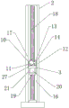
Fig. 1 is a schematic front view of a green plant trimming device for landscaping according to the present invention.
Fig. 2 is a schematic side view of the green plant trimming device for landscaping according to the present invention.
Fig. 3 is a schematic view of a partial bottom view of the green plant trimming device for landscaping according to the present invention.
Fig. 4 is a schematic partial sectional view of a green plant trimming device for landscaping according to the present invention.
Fig. 5 is a partially enlarged schematic structural view of a green plant trimming device for landscaping according to the present invention.
In the figure: 1. moving the chassis; 2. a support pillar; 3. a cross beam; 4. rotating the base; 5. a fixed block; 6. fixing a blade; 7. a sliding blade; 8. a support sheet; 9. adjusting the push rod; 10. a sleeve; 11. inserting a rod; 12. a linear module; 13. a slider; 14. connecting sheets; 15. mounting blocks; 16. a lifting groove; 17. a through groove; 18. rotating the screw rod; 19. rotating the block; 20. a supporting seat; 21. a triangular bracket; 22. a slide bar; 23. a return spring; 24. a roller; 25. damping suspension; 26. installing a bolt; 27. a slide bar; 28. fixing the bolt; 29. a slide block.
Detailed Description
The present invention is described in detail with reference to the accompanying drawings, as shown in fig. 1-5, the present embodiment is characterized by comprising a moving chassis 1, a supporting column 2, a lifting mechanism, a beam 3 and a collecting mechanism, wherein the center of the moving chassis 1 is provided with the supporting column 2, the supporting column 2 is connected with the top surface of the moving chassis 1 and is provided with the lifting mechanism, the beam 3 is installed on the lifting mechanism, the beam 3 is provided with an adjusting sliding mechanism, and the adjusting sliding mechanism is provided with a trimming action structure; the trimming action structure comprises: the device comprises a rotating base 4, a fixed block 5, a fixed blade 6, a sliding blade 7, a pair of supporting sheets 8, a rebound assembly and an adjusting push rod 9; the rotary base 4 is assembled on the sliding adjusting mechanism, the fixed block 5 is arranged on the bottom surface of the rotary base 4, the fixed blade 6 is installed on the fixed block 5, a slide way is formed in the bottom surface of the rotary base 4 and located on one side of the fixed blade 6, the sliding blade 7 is assembled on the slide way, the sliding blade 7 is arranged on the slide way, the sharp edge of the sliding blade 7 is occluded with the sharp edge of the fixed blade 6, a pair of matched supporting sheets 8 are arranged on the sliding blade 7 and the fixed blade 6, a matched rebounding assembly is arranged between the pair of supporting sheets 8, one side of the supporting sheet 8 on the sliding blade 7 is connected with an adjusting push rod; this pruning device is planted with green for afforestation, simple structure, convenient operation can move by oneself, carries out the pruning of relevant position according to setting for, is equipped with elevating system and adjusts glide machanism on the pruning device, can carry out height and horizontal regulation according to the demand to the pruning that the interlock was carried out to the automatic reciprocal pruning action structure of drive, and then carries out comparatively simple automatic pruning, alleviates staff's pruning pressure, overall structure is simple with low costs.
All the electrical components in the present application are connected with the power supply adapted to the electrical components through the wires, and an appropriate controller should be selected according to actual conditions to meet the control requirements, and specific connection and control sequences should be obtained.
Example (b): as can be seen from the attached drawings 1-5 of the specification, the green plant pruning device for landscaping comprises a movable chassis 1, a support column 2, a lifting mechanism, a cross beam 3 and a collecting mechanism, wherein the support column 2 is arranged in the center of the movable chassis 1, the support column 2 is connected with the top surface of the movable chassis 1 and is provided with the lifting mechanism, the cross beam 3 is installed on the lifting mechanism, an adjusting and sliding mechanism is arranged on the cross beam 3, a pruning action structure is arranged on the adjusting and sliding mechanism, in the specific implementation process, the movable chassis 1 can automatically move, a power supply is arranged on the movable chassis 1 to drive the movable chassis 1 to be used as the energy supply of equipment, two pairs of wheel grooves are formed in the bottom surface of the movable chassis 1, two pairs of rollers 24 are arranged in the two pairs of wheel grooves, two pairs of shock absorption suspensions 25 are arranged between, the lifting mechanism on the movable chassis 1 drives the cross beam 3 to move up and down for height adjustment, the sliding mechanism is adjusted to drive the trimming action structure to move transversely to determine the trimming position, and trimming is carried out through the trimming action structure;
as can be seen from fig. 1 to 5 of the specification, the lifting mechanism includes: the lifting groove 16, the through groove 17, the rotary screw 18, the rotary block 19 and the support base 20 are connected and positioned as follows;
the horizontal lifting groove 16 of perpendicular to is seted up at support column 2 center, lifting groove 16 is the cavity cell body of rectangle structure, logical groove 17 has been seted up to lifting groove 16 one side, movable mounting has rotatory lead screw 18 in the lifting groove 16, the cover is equipped with rotatory piece 19 on the rotatory lead screw 18, rotatory piece 19 and 18 threaded engagement of rotatory lead screw, be equipped with supporting seat 20 on the rotatory piece 19, crossbeam 3 is installed in supporting seat 20 one side, supporting seat 20 matches with lifting groove 16 size, crossbeam 3 width matches with the width that leads to groove 17.
In the specific implementation process, through the rotation of rotatory lead screw 18, make the screw thread of rotatory lead screw 18 and rotatory piece 19 meshing, make rotatory piece 19 do perpendicular and horizontally motion, and then drive supporting seat 20 and carry out the altitude variation, drive crossbeam 3 and carry out the altitude mixture control, be equipped with a pair of A-frame 21 between supporting seat 20 and the crossbeam 3 for strengthen the stability of being connected of supporting seat 20 and crossbeam 3, through 16 limit support seats 20 in lift groove, utilize logical groove 17 limit beam 3, and then make supporting seat 20 drive crossbeam 3 and carry out the altitude mixture control and slide.
As can be seen from fig. 1 to 5 of the specification, the adjusting slip mechanism comprises: the connecting structure comprises a sleeve 10, an inserted link 11, a linear module 12, a sliding block 13, a connecting piece 14 and a mounting block 15, wherein the connecting relation and the position relation are as follows;
the top surface of the crossbeam 3 is provided with a sleeve 10, a cylindrical cavity is arranged in the sleeve 10, an insertion rod 11 is inserted into the sleeve 10, a linear module 12 is arranged on the top surface of the crossbeam 3 and positioned on one side of the sleeve 10, a sliding block 13 is arranged on the linear module 12, a sliding groove is arranged on one side of the sleeve 10, a connecting piece 14 is arranged on the sliding block 13 and penetrates through the sliding groove to be connected with the insertion rod 11, an installation block 15 is arranged at the end part of the insertion rod 11, and the rotating base 4 is installed on;
in the concrete implementation process, slide block 13 through on the straight line module 12 drives connection piece 14 and slides, thereby make connection piece 14 slide on the sliding tray, utilize the spacing connection piece 14 of sliding tray, sleeve 10 is spacing with 11 cartridge of inserted bar, it slides in sleeve 10 to drive inserted bar 11 through straight line module 12, the side ring is equipped with a plurality of spouts in sleeve 10, 11 outer rings of inserted bar are equipped with a plurality of slivers 27 cartridge in a plurality of spouts, utilize the relative motion between the spacing inserted bar 11 of slivers 27 and sleeve 10, installation piece 15 has been seted up the circular slot cover with 11 end connection of inserted bar and has been located 11 tip of inserted bar, the circular slot outer ring is equipped with a plurality of construction bolts 26 and fixes, installation piece 15 accessible construction bolt 26 dismantles.
As can be seen from fig. 1 to 5 of the specification, the above-mentioned trimming operation structure includes: the device comprises a rotating base 4, a fixed block 5, a fixed blade 6, a sliding blade 7, a pair of supporting sheets 8, a rebound assembly and an adjusting push rod 9, wherein the connection relationship and the position relationship are as follows;
rotating base 4 assembles on adjusting glide machanism, rotating base 4 bottom surface is equipped with fixed block 5, fixed blade 6 is installed on fixed block 5, rotating base 4 bottom surface just is located fixed blade 6 one side and has seted up the slide, slide blade 7 assembles on the slide, be equipped with slide blade 7 on the slide, slide blade 7 and fixed blade 6's sharp edge interlock, slide blade 7 and fixed blade 6 are last to be equipped with a pair of backing sheet 8 that matches, be equipped with the resilience subassembly of matching between a pair of backing sheet 8, 8 one side of backing sheet on the slide blade 7 is connected with the regulation push rod 9, the flexible end and the backing sheet 8 of regulation push rod 9 are connected.
In the specific implementation process, the rotating base 4 can rotate on the mounting block 15, the fixing bolt 28 is arranged between the fixing block 5 for determining the trimming angle and the fixed blade 6 for connection, the sliding block 29 is arranged at the end of the sliding blade 7 and matched with the slide way, when the linear module 12 sends the mounting block 15 to the trimming position, the adjusting push rod 9 is used for pushing the supporting sheet 8 to enable the sliding blade 7 to slide in the slide way, the sliding blade 7 is further enabled to be close to the fixed blade 6 for occlusion, the tree is trimmed, and the rebounding assembly is used for pushing the supporting sheet 8 to be separated when rebounding.
As can be seen from fig. 1-5 of the specification, the rebound assembly comprises: a slide rod 22, a slide hole, and a return spring 23, which are connected and positioned as follows;
the support sheet 8 on the sliding blade 7 is provided with a sliding rod 22, the support sheet 8 on the fixed blade 6 is provided with a sliding hole, the sliding rod 22 is inserted into the sliding hole, the sliding rod 22 is sleeved with a return spring 23, and two ends of the return spring 23 are supported between the pair of support sheets 8.
In the implementation process, when the sliding sheets are close to each other, the sliding rod 22 is inserted into the sliding hole to press the return spring 23, and when the sliding sheets are returned, the reverse thrust of the return spring 23 is used for pushing away a pair of sliding sheets to move reversely so as to return.
To sum up, this pruning device is planted with green for afforestation, simple structure, convenient operation can remove by oneself, carries out the pruning of relevant position according to setting for, is equipped with elevating system and adjusts glide machanism on the pruning device, can carry out height and horizontal regulation according to the demand to the pruning that the automatic reciprocal pruning action structure of drive carries out reciprocal interlock, and then carries out comparatively simple automatic pruning, alleviates staff's pruning pressure, and overall structure is simple with low costs.
The technical solutions described above only represent the preferred technical solutions of the present invention, and some possible modifications to some parts of the technical solutions by those skilled in the art all represent the principles of the present invention, and fall within the protection scope of the present invention.
Claims (10)
1. A green plant trimming device for landscaping comprises a movable chassis (1), a support column (2), a lifting mechanism, a cross beam (3) and a collecting mechanism, wherein the support column (2) is arranged at the center of the movable chassis (1), the support column (2) is connected with the top surface of the movable chassis (1) and is provided with the lifting mechanism, and the cross beam (3) is installed on the lifting mechanism, and is characterized in that an adjusting sliding mechanism is arranged on the cross beam (3), and a trimming action structure is arranged on the adjusting sliding mechanism;
the trimming action structure includes: the device comprises a rotary base (4), a fixed block (5), a fixed blade (6), a sliding blade (7), a pair of supporting sheets (8), a rebound assembly and an adjusting push rod (9);
rotating base (4) assemble on adjusting glide machanism, rotating base (4) bottom surface is equipped with fixed block (5), install on fixed block (5) fixed blade (6), rotating base (4) bottom surface just is located fixed blade (6) one side and has seted up the slide, slip blade (7) assemble on the slide, be equipped with slip blade (7) on the slide, the sharp sword interlock of slip blade (7) and fixed blade (6), be equipped with backing sheet (8) of a pair of matching on slip blade (7) and fixed blade (6), it is a pair of be equipped with the resilience subassembly of matching between backing sheet (8), backing sheet (8) one side on slip blade (7) is connected with adjusts push rod (9), the flexible end and the backing sheet (8) of adjusting push rod (9) are connected.
2. A green plant trimming apparatus for landscaping as defined in claim 1, wherein the adjusting slide mechanism includes: the device comprises a sleeve (10), an inserted link (11), a linear module (12), a sliding block (13), a connecting piece (14) and a mounting block (15);
crossbeam (3) top surface is equipped with sleeve (10), the cylindricality cavity has been seted up in sleeve (10), inserted bar (11) cartridge is in sleeve (10), it is equipped with sharp module (12) just to be located sleeve (10) one side on crossbeam (3) top surface, be equipped with sliding block (13) on sharp module (12), the sliding tray has been seted up to sleeve (10) one side, it runs through the sliding tray and is connected with inserted bar (11) to be equipped with connection piece (14) on sliding block (13), inserted bar (11) tip is equipped with installation piece (15), rotating base (4) are installed on installation piece (15).
3. A green plant trimming apparatus for use in landscaping, as defined in claim 1, wherein the elevating mechanism comprises: a lifting groove (16), a through groove (17), a rotary screw rod (18), a rotary block (19) and a support seat (20);
the utility model discloses a supporting beam, including support column (2), the horizontal lift groove of perpendicular to (16) has been seted up at the center, lift groove (16) is the cavity cell body of rectangle structure, logical groove (17) have been seted up to lift groove (16) one side, movable mounting has rotatory lead screw (18) in lift groove (16), the cover is equipped with rotatory piece (19) on rotatory lead screw (18), rotatory piece (19) and rotatory lead screw (18) thread engagement, be equipped with supporting seat (20) on rotatory piece (19), install in supporting seat (20) one side crossbeam (3), supporting seat (20) and lift groove (16) size match, crossbeam (3) width matches with the width that leads to groove (17).
4. A green plant trimming apparatus for garden greening according to claim 3, characterized in that a pair of triangular brackets (21) is provided between the supporting base (20) and the cross beam (3).
5. A green plant trimming apparatus for use in landscaping as defined in claim 1, wherein the rebound assembly comprises: a slide rod (22), a slide hole and a return spring (23);
the novel cutting blade is characterized in that a sliding rod (22) is arranged on a supporting sheet (8) on the sliding blade (7), a sliding hole is formed in the supporting sheet (8) of the fixed blade (6), the sliding rod (22) is inserted into the sliding hole, a return spring (23) is sleeved outside the sliding rod (22), and two ends of the return spring (23) are supported between the supporting sheets (8).
6. A pruning device for green plants for landscaping as defined in claim 1, wherein said mobile chassis (1) has two pairs of wheel grooves formed in its bottom surface, two pairs of rollers (24) are disposed in said two pairs of wheel grooves, and two pairs of shock-absorbing suspensions (25) are disposed between said two pairs of rollers (24) and the wheel grooves.
7. A green plant trimming device for garden greening according to claim 2, characterized in that the connection between the mounting block (15) and the end of the inserting rod (11) is provided with a circular groove sleeved on the end of the inserting rod (11), and the outer ring of the circular groove is provided with a plurality of mounting bolts (26) for fixing.
8. A pruning device for green plants for landscaping, as defined in claim 2, wherein said sleeve (10) has a plurality of sliding slots formed around its inner side, and said insertion rod (11) has a plurality of sliding bars (27) formed around its outer periphery for insertion into said plurality of sliding slots.
9. A green plant trimming apparatus for garden greening according to claim 1, wherein the fixing block (5) is connected with the fixed blade (6) by a fixing bolt (28).
10. A green plant trimming apparatus for garden greening according to claim 1, characterized in that the end of the sliding blade (7) is provided with a slider (29) matching with the slideway.
Priority Applications (1)
| Application Number | Priority Date | Filing Date | Title |
|---|---|---|---|
| CN202110201611.2A CN112930911A (en) | 2021-02-23 | 2021-02-23 | Green trimming means that plants for afforestation |
Applications Claiming Priority (1)
| Application Number | Priority Date | Filing Date | Title |
|---|---|---|---|
| CN202110201611.2A CN112930911A (en) | 2021-02-23 | 2021-02-23 | Green trimming means that plants for afforestation |
Publications (1)
| Publication Number | Publication Date |
|---|---|
| CN112930911A true CN112930911A (en) | 2021-06-11 |
Family
ID=76245557
Family Applications (1)
| Application Number | Title | Priority Date | Filing Date |
|---|---|---|---|
| CN202110201611.2A Pending CN112930911A (en) | 2021-02-23 | 2021-02-23 | Green trimming means that plants for afforestation |
Country Status (1)
| Country | Link |
|---|---|
| CN (1) | CN112930911A (en) |
Citations (8)
| Publication number | Priority date | Publication date | Assignee | Title |
|---|---|---|---|---|
| GB391898A (en) * | 1931-12-05 | 1933-05-11 | Owen Frank Stevens | Improved mechanism for cutting hedges and the like |
| CN203251693U (en) * | 2013-05-28 | 2013-10-30 | 长春工业大学 | Espalier trimmer |
| CN205623352U (en) * | 2016-05-07 | 2016-10-12 | 杭州天仁建设环境有限公司 | Tree pruning device |
| CN107360868A (en) * | 2017-07-19 | 2017-11-21 | 佛山市广师自动化科技有限公司 | A kind of comprehensive greenbelt clipping device in municipal gardens |
| CN206658587U (en) * | 2017-03-23 | 2017-11-24 | 吴菲 | A kind of ornamental plant modeling scissors car |
| CN108522058A (en) * | 2018-04-24 | 2018-09-14 | 华南理工大学广州学院 | A kind of electrically driven (operated) hedge trimming device and method |
| CN209030663U (en) * | 2018-10-29 | 2019-06-28 | 四川一贝动力科技有限公司 | A kind of ornamental plant modeling scissors vehicle |
| CN209806525U (en) * | 2019-03-21 | 2019-12-20 | 广东中京建设有限公司 | Municipal afforestation equipment |
-
2021
- 2021-02-23 CN CN202110201611.2A patent/CN112930911A/en active Pending
Patent Citations (8)
| Publication number | Priority date | Publication date | Assignee | Title |
|---|---|---|---|---|
| GB391898A (en) * | 1931-12-05 | 1933-05-11 | Owen Frank Stevens | Improved mechanism for cutting hedges and the like |
| CN203251693U (en) * | 2013-05-28 | 2013-10-30 | 长春工业大学 | Espalier trimmer |
| CN205623352U (en) * | 2016-05-07 | 2016-10-12 | 杭州天仁建设环境有限公司 | Tree pruning device |
| CN206658587U (en) * | 2017-03-23 | 2017-11-24 | 吴菲 | A kind of ornamental plant modeling scissors car |
| CN107360868A (en) * | 2017-07-19 | 2017-11-21 | 佛山市广师自动化科技有限公司 | A kind of comprehensive greenbelt clipping device in municipal gardens |
| CN108522058A (en) * | 2018-04-24 | 2018-09-14 | 华南理工大学广州学院 | A kind of electrically driven (operated) hedge trimming device and method |
| CN209030663U (en) * | 2018-10-29 | 2019-06-28 | 四川一贝动力科技有限公司 | A kind of ornamental plant modeling scissors vehicle |
| CN209806525U (en) * | 2019-03-21 | 2019-12-20 | 广东中京建设有限公司 | Municipal afforestation equipment |
Similar Documents
| Publication | Publication Date | Title |
|---|---|---|
| CN111837687A (en) | Multi-functional afforestation clipping machine | |
| CN107926595B (en) | Gardens are transplanted and are used trees fixing device | |
| CN112930911A (en) | Green trimming means that plants for afforestation | |
| CN212232085U (en) | Pit digging equipment for garden planting | |
| CN216362696U (en) | Angle-adjustable nursery stock pruning device | |
| CN114667854A (en) | A cut device for afforestation | |
| CN212232259U (en) | Pruning device for garden maintenance | |
| CN211210754U (en) | Afforestation plant fixed knot constructs | |
| CN218104254U (en) | Branch and leaf trimming means for afforestation | |
| CN220799190U (en) | Novel arbor is pruned with adjustable rotatory eyelidretractor | |
| CN220235599U (en) | Stabilizing device for transplanting seedlings | |
| CN219395638U (en) | Afforestation trimming machine | |
| CN219577890U (en) | Adjustable municipal landscape flower stand | |
| CN214902587U (en) | Movable shading device for flowers, plants and seedlings for landscape greening | |
| CN216650509U (en) | Trimming means is used in gardens | |
| CN215582776U (en) | Auxiliary fixing support for growth of small seedlings | |
| CN213152851U (en) | Landscape plant machine of making a hole | |
| CN212184281U (en) | Afforestation trimming means | |
| CN218831392U (en) | Greening modeling pruning robot | |
| CN213306274U (en) | Afforestation is with afforestation trimming means | |
| CN216492160U (en) | Special trimming machine for garden maintenance | |
| CN210157703U (en) | Afforestation curing means | |
| CN220493778U (en) | Ornamental trees and shrubs support | |
| CN213187217U (en) | Afforestation is with long arm grass trimmer | |
| CN220965700U (en) | Garden construction trimming device |
Legal Events
| Date | Code | Title | Description |
|---|---|---|---|
| PB01 | Publication | ||
| PB01 | Publication | ||
| SE01 | Entry into force of request for substantive examination | ||
| SE01 | Entry into force of request for substantive examination | ||
| RJ01 | Rejection of invention patent application after publication | ||
| RJ01 | Rejection of invention patent application after publication |
Application publication date: 20210611 |