CN112879420A - Ceramic bearing - Google Patents

Ceramic bearing Download PDF

Info

Publication number
CN112879420A
CN112879420A CN202110048057.9A CN202110048057A CN112879420A CN 112879420 A CN112879420 A CN 112879420A CN 202110048057 A CN202110048057 A CN 202110048057A CN 112879420 A CN112879420 A CN 112879420A
Authority
CN
China
Prior art keywords
oil
groove
sealing
ceramic bearing
wall
Prior art date
Legal status (The legal status is an assumption and is not a legal conclusion. Google has not performed a legal analysis and makes no representation as to the accuracy of the status listed.)
Granted
Application number
CN202110048057.9A
Other languages
Chinese (zh)
Other versions
CN112879420B (en
Inventor
沈睿
张晓宇
Current Assignee (The listed assignees may be inaccurate. Google has not performed a legal analysis and makes no representation or warranty as to the accuracy of the list.)
Nanjing Chaojing Photoelectric New Material Technology Research Institute Co ltd
Original Assignee
Individual
Priority date (The priority date is an assumption and is not a legal conclusion. Google has not performed a legal analysis and makes no representation as to the accuracy of the date listed.)
Filing date
Publication date
Application filed by Individual filed Critical Individual
Priority to CN202110048057.9A priority Critical patent/CN112879420B/en
Publication of CN112879420A publication Critical patent/CN112879420A/en
Application granted granted Critical
Publication of CN112879420B publication Critical patent/CN112879420B/en
Active legal-status Critical Current
Anticipated expiration legal-status Critical

Links

Images

Classifications

    • FMECHANICAL ENGINEERING; LIGHTING; HEATING; WEAPONS; BLASTING
    • F16ENGINEERING ELEMENTS AND UNITS; GENERAL MEASURES FOR PRODUCING AND MAINTAINING EFFECTIVE FUNCTIONING OF MACHINES OR INSTALLATIONS; THERMAL INSULATION IN GENERAL
    • F16CSHAFTS; FLEXIBLE SHAFTS; ELEMENTS OR CRANKSHAFT MECHANISMS; ROTARY BODIES OTHER THAN GEARING ELEMENTS; BEARINGS
    • F16C19/00Bearings with rolling contact, for exclusively rotary movement
    • F16C19/22Bearings with rolling contact, for exclusively rotary movement with bearing rollers essentially of the same size in one or more circular rows, e.g. needle bearings
    • F16C19/34Bearings with rolling contact, for exclusively rotary movement with bearing rollers essentially of the same size in one or more circular rows, e.g. needle bearings for both radial and axial load
    • F16C19/38Bearings with rolling contact, for exclusively rotary movement with bearing rollers essentially of the same size in one or more circular rows, e.g. needle bearings for both radial and axial load with two or more rows of rollers
    • FMECHANICAL ENGINEERING; LIGHTING; HEATING; WEAPONS; BLASTING
    • F16ENGINEERING ELEMENTS AND UNITS; GENERAL MEASURES FOR PRODUCING AND MAINTAINING EFFECTIVE FUNCTIONING OF MACHINES OR INSTALLATIONS; THERMAL INSULATION IN GENERAL
    • F16CSHAFTS; FLEXIBLE SHAFTS; ELEMENTS OR CRANKSHAFT MECHANISMS; ROTARY BODIES OTHER THAN GEARING ELEMENTS; BEARINGS
    • F16C33/00Parts of bearings; Special methods for making bearings or parts thereof
    • F16C33/30Parts of ball or roller bearings
    • F16C33/38Ball cages
    • F16C33/40Ball cages for multiple rows of balls
    • FMECHANICAL ENGINEERING; LIGHTING; HEATING; WEAPONS; BLASTING
    • F16ENGINEERING ELEMENTS AND UNITS; GENERAL MEASURES FOR PRODUCING AND MAINTAINING EFFECTIVE FUNCTIONING OF MACHINES OR INSTALLATIONS; THERMAL INSULATION IN GENERAL
    • F16CSHAFTS; FLEXIBLE SHAFTS; ELEMENTS OR CRANKSHAFT MECHANISMS; ROTARY BODIES OTHER THAN GEARING ELEMENTS; BEARINGS
    • F16C33/00Parts of bearings; Special methods for making bearings or parts thereof
    • F16C33/30Parts of ball or roller bearings
    • F16C33/58Raceways; Race rings
    • F16C33/583Details of specific parts of races
    • FMECHANICAL ENGINEERING; LIGHTING; HEATING; WEAPONS; BLASTING
    • F16ENGINEERING ELEMENTS AND UNITS; GENERAL MEASURES FOR PRODUCING AND MAINTAINING EFFECTIVE FUNCTIONING OF MACHINES OR INSTALLATIONS; THERMAL INSULATION IN GENERAL
    • F16CSHAFTS; FLEXIBLE SHAFTS; ELEMENTS OR CRANKSHAFT MECHANISMS; ROTARY BODIES OTHER THAN GEARING ELEMENTS; BEARINGS
    • F16C33/00Parts of bearings; Special methods for making bearings or parts thereof
    • F16C33/30Parts of ball or roller bearings
    • F16C33/66Special parts or details in view of lubrication
    • F16C33/6637Special parts or details in view of lubrication with liquid lubricant
    • F16C33/664Retaining the liquid in or near the bearing
    • FMECHANICAL ENGINEERING; LIGHTING; HEATING; WEAPONS; BLASTING
    • F16ENGINEERING ELEMENTS AND UNITS; GENERAL MEASURES FOR PRODUCING AND MAINTAINING EFFECTIVE FUNCTIONING OF MACHINES OR INSTALLATIONS; THERMAL INSULATION IN GENERAL
    • F16CSHAFTS; FLEXIBLE SHAFTS; ELEMENTS OR CRANKSHAFT MECHANISMS; ROTARY BODIES OTHER THAN GEARING ELEMENTS; BEARINGS
    • F16C33/00Parts of bearings; Special methods for making bearings or parts thereof
    • F16C33/72Sealings
    • F16C33/76Sealings of ball or roller bearings
    • F16C33/78Sealings of ball or roller bearings with a diaphragm, disc, or ring, with or without resilient members
    • F16C33/7816Details of the sealing or parts thereof, e.g. geometry, material

Landscapes

  • Engineering & Computer Science (AREA)
  • General Engineering & Computer Science (AREA)
  • Mechanical Engineering (AREA)
  • Rolling Contact Bearings (AREA)

Abstract

The invention relates to the field of bearings, in particular to a ceramic bearing, which comprises an outer ring, a retainer, rollers and an inner ring, and further comprises a sealing structure, wherein the retainer is arranged between the outer ring and the inner ring, the retainer is uniformly provided with a plurality of rollers, two sides of the retainer are respectively provided with the sealing structure, the sealing structure comprises a sealing plate, a sealing spring and a rubber sealing ring, two ends of the outer wall of the inner ring are respectively surrounded with a first sealing groove, the sealing plate is clamped with the inner ring through the first sealing groove, the ceramic bearing can automatically and dynamically lubricate, simultaneously filters internal lubricating oil to remove dirt in the lubricating oil, ensures the lubricating environment of the ceramic bearing, realizes cooling through liquid in the high-speed rotation process, has high efficiency and high speed, is not easy to break when impacted, and plays a good role in protecting the ceramic bearing while dissipating heat and cooling, the service life of the ceramic bearing is prolonged.

Description

Ceramic bearing
Technical Field
The invention relates to the field of bearings, in particular to a ceramic bearing.
Background
The Bearing (Bearing) is a part for fixing and reducing the friction coefficient of load in the mechanical transmission process, and its main function is to support the mechanical rotating body, reduce the friction coefficient in the motion process, and ensure the rotation precision, also can be said, when other parts produce relative motion on the shaft, the part for reducing the friction coefficient in the power transmission process and keeping the shaft center position fixed, the Bearing is a very important part in the present mechanical equipment, the ceramic Bearing is one kind of Bearing, because it has the superior performance that the metal Bearing can not compare, the high temperature resistance, the super strength, etc. are used in the new material world at first, in recent more than ten years, and have been increasingly widely used in various fields of the national civilization.
Zirconia ceramic bearing is adopted on current computer CUP radiator fan more, but the existence can't refuel in the use and lubricate, and the most high-speed operation of CPU radiator, high-speed rotation in-process easily generates heat, easily causes the fan to burn out, meets the easy broken scheduling problem of impact, seriously influences ceramic bearing's life-span.
Disclosure of Invention
Aiming at the problems in the prior art, the invention provides a ceramic bearing which realizes automatic dynamic lubrication in the working process, simultaneously filters internal lubricating oil to remove dirt in the lubricating oil, ensures the lubricating environment of the ceramic bearing, realizes cooling through liquid in the high-speed rotation process, has high efficiency and high speed of cooling, is not easy to break when impacted, plays a good role in protecting the ceramic bearing while playing a role in heat dissipation and cooling, and prolongs the service life of the ceramic bearing.
The technical scheme adopted by the invention for solving the technical problems is as follows: the utility model provides a ceramic bearing, includes outer lane, holder, roller and inner circle this ceramic bearing still includes seal structure, the holder is arranged in between outer lane and the inner circle, a plurality of rollers of even installation in the holder, the holder both sides all are equipped with seal structure, seal structure includes closing plate, sealing spring and rubber seal ring, the outer wall both ends of inner circle are encircleed and are equipped with first seal groove, the closing plate is through first seal groove and inner circle joint, the closing plate lateral wall is equipped with the annular spring groove, sealing spring arranges the annular spring inslot in, closing plate outer wall middle part all encircles and is equipped with the second seal groove, the rubber seal ring is arranged in the second seal groove, and with the.
Specifically, the inside oil groove of leading that is equipped with of closing plate, the closing plate internal surface is equipped with one-way oil outlet, first oil groove and the one-way oil outlet link up the setting of leading, the closing plate inboard is equipped with the second and leads the oil groove, the second is led and is connected with through the axis of rotation and lead the oiled-plate in the oil groove.
Specifically, the oil tank bottom is led to the second and is equipped with the filtration oil inlet, it runs through the closing plate to filter the oil inlet, it is equipped with on the one-way oil outlet one side inner wall to keep away from to first oil groove and filters the oil-out, filter the oil-out and run through the closing plate, and with it is coaxial to filter the oil inlet, it separates through the baffle to filter between oil-out and the filtration oil inlet, can dismantle on the closing plate outer wall and be connected with the filter core, just the oil inlet and the oil-out of filter core correspond respectively to connect.
Specifically, the middle part of the outer wall of the outer ring is provided with a buffer groove, a plurality of water bags are fixedly connected in the buffer groove, the water bags are connected in a through mode through a connecting pipe, an oil changing hole is formed in one side of the outer wall of the outer ring, and a sealing plug matched with the oil changing hole is arranged inside the oil changing hole.
Specifically, the retainer middle part is equipped with annular oil groove, be equipped with a plurality of oil through holes on the annular oil groove, oil through hole one end fixedly connected with overhead gage, the opposite side fixedly connected with lower baffle of the oil through hole other end, overhead gage and lower baffle slope setting in opposite directions.
The invention has the beneficial effects that:
(1) the ceramic bearing has the advantages that the outer ring rotates relative to the inner ring, the rollers between the outer ring and the inner ring rotate simultaneously, the retainer is driven to rotate together in the rotation process of the rollers, the outer ring has a heat dissipation function simultaneously during transmission, the retainer is arranged to support and mount the rollers, the circulating flow of lubricating oil in the ceramic bearing is accelerated, the sealing plate is always in a static state relative to the inner ring, the inner ring of the sealing plate is arranged in the first sealing groove and is arranged in the annular spring groove through the sealing spring to realize the sealing between the sealing plate and the inner ring, the sealing plate is provided with the second sealing groove, the rubber sealing ring is arranged in the second sealing groove and is contacted with the inner wall of the outer ring through the rubber sealing ring, the sealing between the sealing plate and the outer ring is realized, the ceramic bearing is ensured not to have oil leakage phenomenon, and meanwhile, dust is prevented from entering the ceramic bearing, the effect of assisting lubrication is achieved, the purposes of filtering lubricating oil and sealing are achieved, and the service life of the ceramic bearing is prolonged.
(2) According to the ceramic bearing, the middle part of the outer surface of the outer ring is provided with the buffer groove, the plurality of water bags are fixedly connected in the buffer groove, the water bags play a role in buffering and radiating, the plurality of water bags are communicated through the connecting pipe, and the internal liquid is quickly transferred and circulated.
(3) According to the ceramic bearing, lubricating oil in the ceramic bearing flows along the annular oil groove, flows to one side of the inner wall of the retainer along the oil through hole under the action of the upper baffle plate in the flowing process of the lubricating oil, and continuously flows to two sides along the inner wall of the retainer to continuously and dynamically lubricate a roller; when the roller rotates anticlockwise, the lubricating oil flows to one side of the outer wall of the retainer along the oil through hole under the action of the lower baffle plate in the flowing process of the lubricating oil, and the lubricating oil continuously flows to two sides along the outer wall of the retainer to dynamically lubricate the roller continuously.
Drawings
The invention is further illustrated with reference to the following figures and examples.
Fig. 1 is a perspective view of a ceramic bearing according to the present invention.
Fig. 2 is a perspective view of the cage and rollers provided by the present invention.
Fig. 3 is a partial cross-sectional view of fig. 2 provided in accordance with the present invention.
Fig. 4 is an enlarged view of the area a in fig. 3 according to the present invention.
Fig. 5 is a perspective view of a seal structure provided by the present invention.
Fig. 6 is an axial view of fig. 5 provided by the present invention.
FIG. 7 is a perspective view of the oil guide plate and the rotating shaft provided by the present invention
FIG. 8 is a schematic view of the relationship between the positions of the second oil guiding groove and the oil filtering inlet provided by the present invention.
Fig. 9 is a cross-sectional view of fig. 8 provided by the present invention.
Fig. 10 is a perspective view of a filter cartridge provided by the present invention.
Fig. 11 is a cross-sectional view of fig. 10 provided by the present invention.
In the figure: 1. an outer ring; 11. a water bladder; 12. a connecting pipe; 13. a buffer tank; 14. an oil changing hole; 2. a holder; 21. a roller; 22. an annular oil groove; 23. an oil through hole; 24. an upper baffle plate; 25. a lower baffle plate; 3. an inner ring; 31. a first seal groove; 4. a sealing structure; 41. a sealing plate; 411. an oil guide plate; 412. a rotating shaft; 413. a filter element; 4131. a filtering oil inlet; 4132. filtering the oil outlet; 414. a first oil guide groove; 415. a one-way oil outlet hole; 416. a second oil guide groove; 42. a seal spring; 43. a rubber seal ring.
Detailed Description
In order to make the technical means, the creation characteristics, the achievement purposes and the effects of the invention easy to understand, the invention is further described with the specific embodiments.
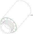
As shown in fig. 1 to 11, the ceramic bearing according to the present invention includes an outer ring 1, a cage 2, rollers 21, and an inner ring 3, and is characterized in that: the ceramic bearing also comprises a sealing structure 4, the retainer 2 is arranged between the outer ring 1 and the inner ring 3, a plurality of rollers 21 are uniformly arranged in the retainer 2, the sealing structures 4 are arranged on two sides of the retainer 2, the sealing structure 4 comprises a sealing plate 41, a sealing spring 42 and a rubber sealing ring 43, a first sealing groove 31 is arranged at two ends of the outer wall of the inner ring 3 in a surrounding manner, the sealing plate 41 is clamped with the inner ring 3 through the first sealing groove 31, an annular spring groove is arranged on the outer side wall of the sealing plate 41, the sealing spring 42 is arranged in the annular spring groove, a second sealing groove is arranged in the middle of the outer wall of the sealing plate 41 in a surrounding manner, the rubber sealing ring 43 is arranged in the second sealing groove and is contacted with the inner wall of the outer ring 1, the outer ring 1 rotates relative to the inner ring 3, the rollers 21 between the outer ring 1 and the inner ring 3, play supporting role and installation effect to roller 21 through setting up holder 2, still have the function of accelerating the interior lubricating oil circulation flow of this ceramic bearing simultaneously, the relative inner circle 3 of closing plate 41 is in quiescent condition always, the closing plate 41 inner ring is arranged in first seal groove 31, and arrange the annular spring inslot in through sealing spring 42, realize sealed between closing plate 41 and the inner circle 3, be equipped with the second seal groove on the closing plate 41, rubber seal ring 43 is arranged in the second seal groove, through rubber seal ring 43 and 1 inner wall contact in outer lane, sealing between closing plate 41 and outer lane 1 has been realized, ensure this ceramic bearing oil leak phenomenon can not appear, avoid having the dust to get into this ceramic bearing simultaneously and influence normal work, the effect of assisting lubrication has been reached, the mesh of filtering lubricating oil and sealing has been realized simultaneously, the life-span of this ceramic bearing has been prolonged.
Specifically, the inside first oil groove 414 that leads that is equipped with of sealing plate 41, sealing plate 41 internal surface is equipped with one-way oil outlet 415, first oil groove 414 and one-way oil outlet 415 link up the setting of leading, sealing plate 41 inboard is equipped with the second and leads oil groove 416, it is connected with through rotation axis 412 rotation in the oil groove 416 to lead the second leads oil groove 411, and this ceramic bearing rotates the in-process, and inside lubricating oil also can flow, makes to lead oil plate 411 along rotation axis 412 axial rotation through the mobile thrust of lubricating oil, and lubricating oil gets into the second along leading oil groove 416 along leading oil plate 411 simultaneously, and the lubricating oil after the filtration flows out through one-way oil outlet 415 from first oil groove 414 of leading, realizes the dynamic filtration of lubricating oil in the course of the work.
Specifically, the bottom of the second oil guiding groove 416 is provided with a filtering oil inlet 4131, the filtering oil inlet 4131 penetrates through the sealing plate 41, the inner wall of the first oil guiding groove 414, which is away from the one-way oil outlet 415, is provided with a filtering oil outlet 4132, the filtering oil outlet 4132 penetrates through the sealing plate 41 and is coaxial with the filtering oil inlet 4131, the filtering oil outlet 4132 is separated from the filtering oil inlet 4131 by a partition, the outer wall of the sealing plate 41 is detachably connected with a filter element 413, and the oil inlet and the oil outlet of the filter element 413 are respectively and correspondingly connected with the filtering oil inlet 4131 and the filtering oil outlet 4132, meanwhile, the retainer 2 drives the lubricating oil to flow clockwise during the rotation process, one end of the oil guiding plate 411 is thrust by the flowing of the lubricating oil and starts to rotate axially along the rotating shaft 412, so that the lubricating oil enters the second oil guiding groove 416 along the oil guiding, can collect and get rid of the impurity in this ceramic bearing through filter core 413, the machine oil after the filtration flows to first oil groove 414 in through filtering oil outlet 4132, flows out through one-way oil outlet 415 at last, has further realized the dynamic filtration of lubricating oil, has got rid of the impurity in the lubricating oil, has further prolonged this ceramic bearing's life-span.
Specifically, a buffer groove 13 is formed in the middle of the outer wall of the outer ring 1, a plurality of water bags 11 are fixedly connected in the buffer groove 13, the water bags 11 are communicated and connected through a connecting pipe 12, an oil changing hole 14 is formed in one side of the outer wall of the outer ring 1, a sealing plug matched with the oil changing hole 14 is arranged in the oil changing hole 14, the sealing plug matched with the oil changing hole 14 is firstly pulled out in the year before installation and use, lubricating oil is injected through the oil changing hole 14, and the sealing plug is plugged again after injection, so that the ceramic bearing is smoother in the working process, and the friction force is reduced; outer lane 1 surface middle part is equipped with dashpot 13, a plurality of water sacs 11 of fixedly connected with in dashpot 13, water sac 11 plays cushioning effect and radiating effect, a plurality of water sacs 11 pass through connecting pipe 12 intercommunication, the fast transfer circulation of inside liquid, it is to receive the impact when one of them water sac 11, inside liquid realizes the buffering in the middle of flowing another water sac 11 through connecting pipe 12, avoid this ceramic bearing direct atress to appear broken phenomenon, the most high-speed operation of CPU radiator, high-speed rotation in-process is easily generated heat, cool down the heat dissipation through the liquid in the water sac 11, play fine cushioning effect again and play fine guard action to ceramic bearing when receiving external impact simultaneously, further the life-span of this ceramic bearing has been prolonged.
Specifically, an annular oil groove 22 is formed in the middle of the retainer 2, a plurality of oil through holes 23 are formed in the annular oil groove 22, one end of each oil through hole 23 is fixedly connected with an upper baffle plate 24, the opposite side of the other end of each oil through hole 23 is fixedly connected with a lower baffle plate 25, the upper baffle plates 24 and the lower baffle plates 25 are arranged in an opposite inclined mode and rotate clockwise, lubricating oil in the ceramic bearing flows along the annular oil groove 22, the lubricating oil flows to one side of the inner wall of the retainer 2 along the oil through holes 23 under the action of the upper baffle plates 24 in the flowing process of the lubricating oil, and the lubricating oil continuously flows to two sides along the inner wall of the retainer 2 to dynamically; when the roller rotates anticlockwise, the lubricating oil flows to one side of the outer wall of the retainer 2 along the oil through hole 23 under the action of the lower baffle plate 25 in the flowing process of the lubricating oil, and the lubricating oil continuously flows to two sides along the outer wall of the retainer 2 to dynamically lubricate the roller 21 continuously.
According to the working principle, in the year before installation and use, the sealing plug matched with the oil changing hole 14 is firstly pulled out, lubricating oil is injected through the oil changing hole 14, and the sealing plug is plugged again after the lubricating oil is injected, so that the ceramic bearing is smoother in the working process, and the friction force is reduced;
in the working process, the outer ring 1 rotates relative to the inner ring 3, the roller 21 between the outer ring 1 and the inner ring 3 rotates simultaneously, the retainer 2 is driven to rotate together in the rotation process of the roller 21, at the moment, the sealing plate 41 is in a static state relative to the inner ring 3, the inner ring of the sealing plate 41 is arranged in the first sealing groove 31 and is arranged in the annular spring groove through the sealing spring 42, the sealing between the sealing plate 41 and the inner ring 3 is realized, the sealing plate 41 is provided with a second sealing groove, the rubber sealing ring 43 is arranged in the second sealing groove, and the sealing between the sealing plate 41 and the outer ring 1 is realized through the contact of the rubber sealing ring 43 and the inner;
in the working process, when the ceramic bearing rotates clockwise, the lubricating oil in the ceramic bearing flows along the annular oil groove 22, the lubricating oil flows to one side of the inner wall of the retainer 2 along the oil through hole 23 under the action of the upper baffle plate 24 in the flowing process, the lubricating oil continuously flows to two sides along the inner wall of the retainer 2 to continuously and dynamically lubricate the roller 21, meanwhile, the retainer 2 rotates clockwise, the lubricating oil reversely flows relative to the retainer 2, one end of the oil guide plate 411 is thrust by the flowing of the lubricating oil and starts to rotate axially along the rotating shaft 412, so that the lubricating oil enters the second oil guide groove 416 along the oil guide plate 411, the lubricating oil enters the filter element 413 through the filter oil inlet 4131 to filter the lubricating oil, impurities in the ceramic bearing can be collected and removed through the filter element 413, the filtered lubricating oil flows into the first oil guide groove 414 through the filter oil outlet 4132 and finally flows out through the one-way oil, in the flowing process of the lubricating oil, the lubricating oil flows to one side of the outer wall of the retainer 2 along the oil through hole 23 under the action of the lower baffle plate 25, the lubricating oil continuously flows to two sides along the outer wall of the retainer 2 to perform continuous dynamic lubrication on the roller 21, meanwhile, in the rotating process of the retainer 2, the lubricating oil reversely flows relative to the retainer 2, the other end of the oil guide plate 411 receives the thrust of the flowing of the lubricating oil and starts to reversely rotate along the axial direction of the rotating shaft 412, so that the lubricating oil enters the second oil guide groove 416 along the oil guide plate 411, enters the filter element 413 through the filter oil inlet 4131 to filter the engine oil, impurities in the ceramic bearing can be collected and removed through the filter element 413, the filtered engine oil flows into the first oil guide groove 414 through the filter oil outlet 4132 and finally flows out through the one-way oil outlet 415, the ceramic bearing utilizes the power in the working process to realize the dynamic lubrication, the ceramic bearing has the advantages that the oil leakage phenomenon can not occur, meanwhile, dust is prevented from entering the ceramic bearing to influence normal work, the effect of assisting lubrication is achieved, the purposes of filtering lubricating oil and sealing are achieved, and the service life of the ceramic bearing is prolonged.
When this ceramic bearing receives external impact, 1 surface middle part in outer lane is equipped with dashpot 13, a plurality of water sacs 11 of fixedly connected with in dashpot 13, water sacs 11 play cushioning effect and radiating effect, a plurality of water sacs 11 pass through connecting pipe 12 intercommunication, the fast transfer circulation of inside liquid, it is to receive the impact when one of them water sac 11, inside liquid passes through connecting pipe 12 and flows and realize the buffering in the middle of another water sac 11, avoid this ceramic bearing direct atress breaking phenomenon to appear, the most high-speed operation of CPU radiator, high-speed rotation in-process easily generates heat, liquid through in the water sac 11 cools down the heat dissipation, play fine cushioning effect again and play fine guard action to ceramic bearing when receiving external impact simultaneously, further extension this ceramic bearing's life-span.
The foregoing illustrates and describes the principles, general features, and advantages of the present invention. It will be understood by those skilled in the art that the present invention is not limited to the embodiments described above, and the embodiments and descriptions given above are only illustrative of the principles of the present invention, and various changes and modifications may be made without departing from the spirit and scope of the invention, which fall within the scope of the claims. The scope of the invention is defined by the appended claims and equivalents thereof.

Claims (5)

1. A ceramic bearing, includes outer lane (1), holder (2), roller (21) and inner circle (3), its characterized in that: this ceramic bearing still includes seal structure (4), holder (2) are arranged in between outer lane (1) and inner circle (3), evenly install a plurality of rollers (21) in holder (2), holder (2) both sides all are equipped with seal structure (4), seal structure (4) include closing plate (41), sealing spring (42) and rubber seal ring (43), the outer wall both ends of inner circle (3) all encircle and are equipped with first seal groove (31), closing plate (41) are through first seal groove (31) and inner circle (3) joint, closing plate (41) lateral wall is equipped with the annular spring groove, annular spring inslot is arranged in sealing spring (42), closing plate (41) outer wall middle part encircles and is equipped with the second seal groove, rubber seal ring (43) are arranged in the second seal groove, and with outer lane (1) inner wall contact.
2. A ceramic bearing according to claim 1, wherein: the inside oil groove (414) of leading that is equipped with of closing plate (41), closing plate (41) internal surface is equipped with one-way oil outlet (415), first oil groove (414) of leading link up the setting with one-way oil outlet (415), closing plate (41) inboard is equipped with the second and leads oil groove (416), it is connected with through axis of rotation (412) rotation and leads oiled-plate (411) in oil groove (416) to lead the second.
3. A ceramic bearing according to claim 2, wherein: the oil filter is characterized in that a filtering oil inlet (4131) is arranged at the bottom of the second oil guide groove (416), the filtering oil inlet (4131) penetrates through the sealing plate (41), a filtering oil outlet (4132) is arranged on the inner wall of one side, away from the one-way oil outlet (415), of the first oil guide groove (414), the filtering oil outlet (4132) penetrates through the sealing plate (41) and is coaxial with the filtering oil inlet (4131), the filtering oil outlet (4132) and the filtering oil inlet (4131) are separated through a partition plate, a filter element (413) is detachably connected to the outer wall of the sealing plate (41), and the oil inlet and the oil outlet of the filter element (413) are respectively and correspondingly connected with the filtering oil inlet (4131) and.
4. A ceramic bearing according to claim 3, wherein: the outer lane (1) outer wall middle part is equipped with buffer slot (13), a plurality of water pockets (11) of fixedly connected with in buffer slot (13), through connecting pipe (12) through connection between water pocket (11), outer lane (1) outer wall one side is equipped with trades oilhole (14), trade the inside sealing plug rather than the looks adaptation that is equipped with of oilhole (14).
5. A ceramic bearing according to claim 1, wherein: retainer (2) middle part is equipped with annular oil groove (22), be equipped with a plurality of oil through holes (23) on annular oil groove (22), oil through hole (23) one end fixedly connected with overhead gage (24), baffle (25) under the opposition side fixedly connected with of the oil through hole (23) other end, overhead gage (24) and lower baffle (25) slope setting in opposite directions.
CN202110048057.9A 2021-01-14 2021-01-14 Ceramic bearing Active CN112879420B (en)

Priority Applications (1)

Application Number Priority Date Filing Date Title
CN202110048057.9A CN112879420B (en) 2021-01-14 2021-01-14 Ceramic bearing

Applications Claiming Priority (1)

Application Number Priority Date Filing Date Title
CN202110048057.9A CN112879420B (en) 2021-01-14 2021-01-14 Ceramic bearing

Publications (2)

Publication Number Publication Date
CN112879420A true CN112879420A (en) 2021-06-01
CN112879420B CN112879420B (en) 2022-11-04

Family

ID=76048383

Family Applications (1)

Application Number Title Priority Date Filing Date
CN202110048057.9A Active CN112879420B (en) 2021-01-14 2021-01-14 Ceramic bearing

Country Status (1)

Country Link
CN (1) CN112879420B (en)

Cited By (3)

* Cited by examiner, † Cited by third party
Publication number Priority date Publication date Assignee Title
CN113374794A (en) * 2021-06-15 2021-09-10 邓士全 Stainless steel miniature bearing
CN114576266A (en) * 2022-03-07 2022-06-03 山东华工轴承有限公司 Self-aligning roller bearing based on stirring equipment
CN114704545A (en) * 2022-03-28 2022-07-05 安徽孺子牛轴承有限公司 Strong-magnetic-resistance and rust-proof metal bearing

Citations (26)

* Cited by examiner, † Cited by third party
Publication number Priority date Publication date Assignee Title
FR1281749A (en) * 1960-02-29 1962-01-12 Hermann Kolb Maschinenfabrik G Method for sealing ball bearings
GB1288551A (en) * 1968-06-17 1972-09-13
GB1439138A (en) * 1972-10-24 1976-06-09 Skf Uk Ltd Annular sealing members and assemblies incorporating them
JPS6458813A (en) * 1987-08-28 1989-03-06 Koyo Seiko Co Tapered roller bearing
JP2002220079A (en) * 2001-01-24 2002-08-06 Sanyo Electric Co Ltd Vehicle with assisting power
JP2003343736A (en) * 2002-05-29 2003-12-03 Koyo Sealing Techno Co Ltd Seal ring
DE102004007557A1 (en) * 2004-02-17 2005-09-01 Minebea Co., Ltd. Hydrodynamic bearing system for spindle motor used in hard disk drive, comprises threads formed at circumference of outer bearing which is enclosed by sleeve, such that winding channel is formed between outer bearing and sleeve
JP2008232285A (en) * 2007-03-20 2008-10-02 Jtekt Corp Sealing device for rolling bearing
JP2008303938A (en) * 2007-06-06 2008-12-18 Toyota Motor Corp Oil seal structure
JP2009257414A (en) * 2008-04-15 2009-11-05 Ntn Corp Bearing with pulley
WO2011018447A1 (en) * 2009-08-10 2011-02-17 Magna Steyr Fahrzeugtechnik Ag & Co Kg Electric machine having rolling bearing protected from electrical breakdown and gear motor comprising such a bearing
CN204082934U (en) * 2014-07-01 2015-01-07 嘉善博盛滑动轴承有限公司 A kind of refractory seal bearing support
CN104279385A (en) * 2014-08-13 2015-01-14 杭州优能特旋转接头制造厂 Rotating joint with high sealing property
CN105179464A (en) * 2015-06-14 2015-12-23 海宁市科巍轴承厂 Highly non-compact lubricant-containing ceramic bearing
CN205937513U (en) * 2016-07-15 2017-02-08 新昌县万联轴承有限公司 High -speed sealed rolling mill is used and location bearing
CN106812814A (en) * 2017-03-30 2017-06-09 四川高博环保工程有限公司 It is a kind of for it is interior heating hollow shaft equipment the direct-cooled bearing block of oil cooling type
CN107575492A (en) * 2017-10-24 2018-01-12 无锡民联汽车零部件有限公司 Water cooling high-efficiency heat radiating type bearing
CN207975126U (en) * 2018-01-08 2018-10-16 东莞市奥斯特轴承有限公司 A kind of self sealss self-aligning roller bearing
CN109780070A (en) * 2019-03-16 2019-05-21 杨胜 A kind of anti skid bearing
CN209800550U (en) * 2019-03-14 2019-12-17 湘潭伊模轴承有限公司 Annular double-labyrinth multi-lip spring energy storage sealing device for wind power main bearing
CN209800532U (en) * 2019-03-20 2019-12-17 昆山奇千机械科技有限公司 Possesses dust protected linear slideway who leads oily oil storage box
WO2020027102A1 (en) * 2018-08-01 2020-02-06 イーグル工業株式会社 Slide component
CN111022503A (en) * 2019-11-27 2020-04-17 洛阳轴承研究所有限公司 Roller bearing retainer
CN210661037U (en) * 2019-09-12 2020-06-02 新昌县天地轴承有限公司 Self-lubricating bearing
CN211391623U (en) * 2019-12-14 2020-09-01 江苏国盛船舶有限公司 Marine gasbag convenient to change
CN111853062A (en) * 2020-07-08 2020-10-30 宁波市红业肆零智能科技有限公司 One-way bearing of washing machine

Patent Citations (27)

* Cited by examiner, † Cited by third party
Publication number Priority date Publication date Assignee Title
FR1281749A (en) * 1960-02-29 1962-01-12 Hermann Kolb Maschinenfabrik G Method for sealing ball bearings
GB944158A (en) * 1960-02-29 1963-12-11 Aeroquip Ges Mit Beschraenkter Improvements in or relating to ball bearings
GB1288551A (en) * 1968-06-17 1972-09-13
GB1439138A (en) * 1972-10-24 1976-06-09 Skf Uk Ltd Annular sealing members and assemblies incorporating them
JPS6458813A (en) * 1987-08-28 1989-03-06 Koyo Seiko Co Tapered roller bearing
JP2002220079A (en) * 2001-01-24 2002-08-06 Sanyo Electric Co Ltd Vehicle with assisting power
JP2003343736A (en) * 2002-05-29 2003-12-03 Koyo Sealing Techno Co Ltd Seal ring
DE102004007557A1 (en) * 2004-02-17 2005-09-01 Minebea Co., Ltd. Hydrodynamic bearing system for spindle motor used in hard disk drive, comprises threads formed at circumference of outer bearing which is enclosed by sleeve, such that winding channel is formed between outer bearing and sleeve
JP2008232285A (en) * 2007-03-20 2008-10-02 Jtekt Corp Sealing device for rolling bearing
JP2008303938A (en) * 2007-06-06 2008-12-18 Toyota Motor Corp Oil seal structure
JP2009257414A (en) * 2008-04-15 2009-11-05 Ntn Corp Bearing with pulley
WO2011018447A1 (en) * 2009-08-10 2011-02-17 Magna Steyr Fahrzeugtechnik Ag & Co Kg Electric machine having rolling bearing protected from electrical breakdown and gear motor comprising such a bearing
CN204082934U (en) * 2014-07-01 2015-01-07 嘉善博盛滑动轴承有限公司 A kind of refractory seal bearing support
CN104279385A (en) * 2014-08-13 2015-01-14 杭州优能特旋转接头制造厂 Rotating joint with high sealing property
CN105179464A (en) * 2015-06-14 2015-12-23 海宁市科巍轴承厂 Highly non-compact lubricant-containing ceramic bearing
CN205937513U (en) * 2016-07-15 2017-02-08 新昌县万联轴承有限公司 High -speed sealed rolling mill is used and location bearing
CN106812814A (en) * 2017-03-30 2017-06-09 四川高博环保工程有限公司 It is a kind of for it is interior heating hollow shaft equipment the direct-cooled bearing block of oil cooling type
CN107575492A (en) * 2017-10-24 2018-01-12 无锡民联汽车零部件有限公司 Water cooling high-efficiency heat radiating type bearing
CN207975126U (en) * 2018-01-08 2018-10-16 东莞市奥斯特轴承有限公司 A kind of self sealss self-aligning roller bearing
WO2020027102A1 (en) * 2018-08-01 2020-02-06 イーグル工業株式会社 Slide component
CN209800550U (en) * 2019-03-14 2019-12-17 湘潭伊模轴承有限公司 Annular double-labyrinth multi-lip spring energy storage sealing device for wind power main bearing
CN109780070A (en) * 2019-03-16 2019-05-21 杨胜 A kind of anti skid bearing
CN209800532U (en) * 2019-03-20 2019-12-17 昆山奇千机械科技有限公司 Possesses dust protected linear slideway who leads oily oil storage box
CN210661037U (en) * 2019-09-12 2020-06-02 新昌县天地轴承有限公司 Self-lubricating bearing
CN111022503A (en) * 2019-11-27 2020-04-17 洛阳轴承研究所有限公司 Roller bearing retainer
CN211391623U (en) * 2019-12-14 2020-09-01 江苏国盛船舶有限公司 Marine gasbag convenient to change
CN111853062A (en) * 2020-07-08 2020-10-30 宁波市红业肆零智能科技有限公司 One-way bearing of washing machine

Non-Patent Citations (3)

* Cited by examiner, † Cited by third party
Title
李冬梅等: "汽车油箱中油气分离器设计", 《现代制造技术与装备》 *
杨文英: "锥齿轮轴承套密封及结构改进", 《宁夏机械》 *
邵春明等: "锅炉引风机轴承密封失效分析及改进措施", 《风机技术》 *

Cited By (5)

* Cited by examiner, † Cited by third party
Publication number Priority date Publication date Assignee Title
CN113374794A (en) * 2021-06-15 2021-09-10 邓士全 Stainless steel miniature bearing
CN113374794B (en) * 2021-06-15 2022-12-13 馆陶县宇航轴承制造有限公司 Stainless steel miniature bearing
CN114576266A (en) * 2022-03-07 2022-06-03 山东华工轴承有限公司 Self-aligning roller bearing based on stirring equipment
CN114576266B (en) * 2022-03-07 2023-08-04 山东华工轴承有限公司 Self-aligning roller bearing based on stirring equipment is used
CN114704545A (en) * 2022-03-28 2022-07-05 安徽孺子牛轴承有限公司 Strong-magnetic-resistance and rust-proof metal bearing

Also Published As

Publication number Publication date
CN112879420B (en) 2022-11-04

Similar Documents

Publication Publication Date Title
CN112879420B (en) Ceramic bearing
CN103825404B (en) Motor and variator integrated cooling system
CN102974845A (en) High-speed electric main shaft device
CN212202162U (en) Engine lubricating system, engine assembly and vehicle
CN110666194B (en) Electric spindle
CN107031373A (en) Motor, motor vehicles and the method for running motor
CN112271876A (en) Oil-cooled motor
CN203678432U (en) Bidirectional positive-pressure thin oil sealing device of cone crusher
CN202050316U (en) High-power traction motor bearing lubricating structure
CN202646128U (en) Circular lubricating and heat-radiating bearing oil tank for pump
CN202560621U (en) Blower rolling bearing set with two cooling types
CN202646648U (en) Transfer case and engineering machinery
CN207064480U (en) Rotating shaft assembly and there is its engine
CN203044911U (en) High-speed electric main shaft device
CN216306680U (en) Cooling and lubricating structure of reduction gearbox of pure electric oil-cooled motor
CN213419704U (en) Self-circulation lubricating and cooling structure for bearing at end part of spindle of centrifugal pump
CN211550305U (en) Air-cooled vertical sliding bearing
CN210461382U (en) Self-excitation type oil mist jet lubrication high-speed bearing
CN210068902U (en) Electric drive assembly
CN211275049U (en) Direct-connection transmission disc type separator
CN105697100A (en) Engine with oil filtering and cooling device
CN112780686A (en) Bearing cooling structure and driving motor
CN206211730U (en) Motor and the mine car with it
CN111810538A (en) Light nylon retainer for ball bearing of driving motor
CN213479028U (en) Novel torsional vibration damper of oil feed mode

Legal Events

Date Code Title Description
PB01 Publication
PB01 Publication
SE01 Entry into force of request for substantive examination
TA01 Transfer of patent application right

Effective date of registration: 20221010

Address after: No. 96, Shidai Avenue, Liuhe Economic Development Zone, Nanjing, Jiangsu, 211500

Applicant after: Nanjing Chaojing photoelectric New Material Technology Research Institute Co.,Ltd.

Address before: Unit 1, building 5, Yihe home, No.6 Jianhe Road, Chenghua District, Chengdu, Sichuan 610000

Applicant before: Shen Rui

GR01 Patent grant
GR01 Patent grant
PE01 Entry into force of the registration of the contract for pledge of patent right

Denomination of invention: A ceramic bearing

Effective date of registration: 20230803

Granted publication date: 20221104

Pledgee: China Construction Bank Corporation Nanjing Jiangbei new area branch

Pledgor: Nanjing Chaojing photoelectric New Material Technology Research Institute Co.,Ltd.

Registration number: Y2023980050810