CN112875209B - Full-automatic folding material loading conveyer - Google Patents
Full-automatic folding material loading conveyer Download PDFInfo
- Publication number
- CN112875209B CN112875209B CN202110089914.XA CN202110089914A CN112875209B CN 112875209 B CN112875209 B CN 112875209B CN 202110089914 A CN202110089914 A CN 202110089914A CN 112875209 B CN112875209 B CN 112875209B
- Authority
- CN
- China
- Prior art keywords
- folding
- conveying
- locking
- support
- plate
- Prior art date
- Legal status (The legal status is an assumption and is not a legal conclusion. Google has not performed a legal analysis and makes no representation as to the accuracy of the status listed.)
- Active
Links
Images


Classifications
-
- B—PERFORMING OPERATIONS; TRANSPORTING
- B65—CONVEYING; PACKING; STORING; HANDLING THIN OR FILAMENTARY MATERIAL
- B65G—TRANSPORT OR STORAGE DEVICES, e.g. CONVEYORS FOR LOADING OR TIPPING, SHOP CONVEYOR SYSTEMS OR PNEUMATIC TUBE CONVEYORS
- B65G37/00—Combinations of mechanical conveyors of the same kind, or of different kinds, of interest apart from their application in particular machines or use in particular manufacturing processes
-
- B—PERFORMING OPERATIONS; TRANSPORTING
- B65—CONVEYING; PACKING; STORING; HANDLING THIN OR FILAMENTARY MATERIAL
- B65G—TRANSPORT OR STORAGE DEVICES, e.g. CONVEYORS FOR LOADING OR TIPPING, SHOP CONVEYOR SYSTEMS OR PNEUMATIC TUBE CONVEYORS
- B65G47/00—Article or material-handling devices associated with conveyors; Methods employing such devices
- B65G47/22—Devices influencing the relative position or the attitude of articles during transit by conveyors
-
- F—MECHANICAL ENGINEERING; LIGHTING; HEATING; WEAPONS; BLASTING
- F16—ENGINEERING ELEMENTS AND UNITS; GENERAL MEASURES FOR PRODUCING AND MAINTAINING EFFECTIVE FUNCTIONING OF MACHINES OR INSTALLATIONS; THERMAL INSULATION IN GENERAL
- F16L—PIPES; JOINTS OR FITTINGS FOR PIPES; SUPPORTS FOR PIPES, CABLES OR PROTECTIVE TUBING; MEANS FOR THERMAL INSULATION IN GENERAL
- F16L55/00—Devices or appurtenances for use in, or in connection with, pipes or pipe systems
- F16L55/16—Devices for covering leaks in pipes or hoses, e.g. hose-menders
- F16L55/162—Devices for covering leaks in pipes or hoses, e.g. hose-menders from inside the pipe
-
- B—PERFORMING OPERATIONS; TRANSPORTING
- B65—CONVEYING; PACKING; STORING; HANDLING THIN OR FILAMENTARY MATERIAL
- B65G—TRANSPORT OR STORAGE DEVICES, e.g. CONVEYORS FOR LOADING OR TIPPING, SHOP CONVEYOR SYSTEMS OR PNEUMATIC TUBE CONVEYORS
- B65G2201/00—Indexing codes relating to handling devices, e.g. conveyors, characterised by the type of product or load being conveyed or handled
- B65G2201/02—Articles
- B65G2201/0276—Tubes and pipes
Abstract
The utility model relates to a full-automatic folding material loading conveyer, include the carriage, set up the first conveying mechanism on the carriage and set up in the folding mechanism of conveying mechanism one side, folding mechanism includes folding support, sets up the folding roller on folding support and sets up the actuating mechanism who drives the motion of folding roller on folding roller, folding roller sets up respectively in folding support's both sides, the actuating mechanism drive folding roller rotates. This application has the holistic effect of unreeling of bushing pipe in promoting.
Description
Technical Field
The application relates to the technical field of conveyors, in particular to a full-automatic folding feeding conveyor.
Background
Currently, a conveyor is a device for conveying materials.
At present, carry out prosthetic in-process at practical ultraviolet curing technique to the pipeline, need earlier carry interior bushing pipe to the pipeline in, current interior bushing pipe is at the in-process of carrying, generally need earlier with the hose material both sides of about 0.5 meters of end length respectively towards the interior fifty percent discount one-third, vertical fifty percent discount again to place the hoist and mount area in the fifty percent discount line bottom, the hoist and mount area is connected with the hoist engine couple, realizes unreeling to interior bushing pipe.
However, the folding operation of the lining pipe before the lining pipe is placed in the pipeline needs to be manually completed, the lining pipe needs to be folded for one section in the unreeling process and then sent into the pipeline for one section to be unreeled, unreeling and folding work cannot be completed simultaneously, and construction efficiency is low.
Disclosure of Invention
In order to promote the holistic efficiency of unreeling of bushing pipe, this application provides a full-automatic folding material loading conveyer.
The technical scheme provided by the application is as follows:
the utility model provides a full-automatic folding material loading conveyer, includes the delivery support, sets up first conveying mechanism on the delivery support and sets up in the folding mechanism of delivery mechanism one side, folding mechanism includes folding support, sets up folding roller on folding support and sets up the actuating mechanism who drives folding roller motion on folding roller, folding roller sets up respectively in folding support's both sides, the actuating mechanism drive folding roller rotates.
Through adopting above-mentioned technical scheme, during the use, carry out automatic folding to interior bushing pipe through folding mechanism to make interior bushing pipe not need artifical manual folding at the in-process of carrying, the required time of the interior bushing pipe of artifical folding has been shortened greatly, and make interior bushing pipe can fold at the in-process of carrying automatically, and need not unreel after the completion of artificial folding again, thereby the efficiency of unreeling of interior bushing pipe has been promoted at to a great extent, thereby pipeline repair's construction cycle has been shortened, the performance of enterprises has been promoted.
Optionally, actuating mechanism is including the drive folding roller flexible hydro-cylinder and set up in cylinder end portion and be used for driving the rotatory servo motor of folding roller, each actuating mechanism corresponds a folding roller, actuating mechanism follows the length direction symmetry of folding support set up in the both sides of folding support, flexible hydro-cylinder fixed mounting in on the folding support, the rotatory through-hole that supplies servo motor's output shaft to pass is seted up to the piston rod part of flexible hydro-cylinder, servo motor's output shaft pass behind the rotatory through-hole with folding roller fixed connection.
By adopting the technical scheme, the driving mechanism is set to be the combination of the telescopic oil cylinder and the servo motor, the angle of the folding roller relative to the folding bracket can be adjusted through the servo motor, and thus the inner liner tube can be conveniently folded through adjusting the angle of the folding roller; through setting up flexible hydro-cylinder to make the relative width of two folding rollers can adjust according to the demand of difference, thereby make the interior bushing pipe of different diameters all can realize folding to the bilateral symmetry of interior bushing pipe through beta structure, thereby promoted full-automatic folding material loading conveyer's application scope.
Optionally, a guide block is arranged at a piston rod of the telescopic oil cylinder, a guide groove for embedding the guide block is formed in the side wall of the folding support, and the guide block is embedded in the guide groove and then fixed with the piston rod of the telescopic oil cylinder.
By adopting the technical scheme, the folding bracket can provide supporting force for the guide block in the movement process, the probability of falling between the telescopic oil cylinder and the folding bracket is reduced, and the piston rod of the telescopic oil cylinder can better play a role in supporting the servo motor; and the whole folding roller moves more stably in the sliding process.
Optionally, the folding device further comprises a second conveying mechanism, a folding mechanism and a locking mechanism, wherein the folding mechanism is arranged between the second conveying mechanism and the first conveying mechanism, the folding mechanism is arranged on one side of the second conveying mechanism, the folding mechanism is arranged on one side of the folding mechanism, the lining pipe folded by the folding mechanism is turned backwards, and the locking mechanism locks the overlapped part of the turned lining pipe.
Through adopting above-mentioned technical scheme, can realize compressing tightly to inside lining pipe tip automatically, only need a workman to place the tip of inside lining pipe in the whole work progress on second conveying mechanism, control the operation of full-automatic folding material loading conveyer afterwards and can accomplish unreeling to the pipeline for whole roll-over and compress tightly more automatic, reduced the required manpower of construction at to a great extent, thereby promoted the performance of enterprises to a certain extent.
Optionally, the turnover mechanism comprises a telescopic driving piece arranged at the bottom of the conveying support, an ejector plate arranged at the top of the telescopic driving piece, and a rotary driving piece rotatably arranged at the top of the ejector plate and used for driving the turnover plate to rotate along the ejector plate, wherein the ejector plate is arranged between the first conveying mechanism and the second conveying mechanism, the turnover plate is arranged at the top of the ejector plate, and the top of the turnover plate is flush with the top of the first conveying platform.
By adopting the technical scheme, the rolling of the lining pipe can be realized, and the rolling device is simple in structure and convenient to install.
Optionally, a first conveying platform and a second conveying platform are arranged on the conveying support, the first conveying platform and the second conveying platform are respectively flush with the top of the first conveying mechanism, and the ejector plate is arranged between the first conveying platform and the second conveying platform.
By adopting the technical scheme, the whole lining pipe moves linearly in the conveying process, the deformation of the lining pipe in the conveying process is reduced, and the whole lining pipe is more stable in the conveying process.
Optionally, the turnover mechanism further includes a pressing roller disposed on one side of the turnover plate and pressing brackets disposed on two sides of the pressing roller, the pressing brackets are fixedly mounted on the top of the conveying bracket, the pressing roller is slidably mounted on the pressing brackets, and a positioning gap for the lining tube to pass through is formed between the pressing roller and the conveying bracket.
Through adopting above-mentioned technical scheme, through setting up the compressing roller and compressing tightly the support, can compress tightly folding interior bushing pipe of accomplishing, and can play the effect of location to the in-process that the interior bushing pipe was turning over a book, made things convenient for the board that turns over to turn over a book to the tip of interior bushing pipe.
Optionally, the locking mechanism is arranged on one side of the turnover mechanism far away from the second conveying mechanism, the locking mechanism comprises a pressing assembly arranged on one side of the first conveying mechanism facing the second conveying mechanism and a positioning assembly arranged below the pressing assembly, the pressing assembly comprises a pressing support arranged on the conveying support, a positioning driving piece arranged on the pressing support and a locking buckle detachably mounted at the bottom of the pressing driving piece, the positioning assembly comprises a positioning support arranged on the conveying support, a positioning seat arranged on the positioning support and a positioning buckle detachably mounted at the top of the positioning driving piece, and the locking buckle and the positioning buckle tightly press the lining pipe.
By adopting the technical scheme, the end part of the lining pipe after the turning and the folding are finished can be furled and compressed, so that the turning and the compressing of the lining pipe can be automatically finished by the full-automatic folding feeding conveyor, the labor consumption is greatly reduced, and the cost is reduced; the locking to the inside lining pipe end portion is realized to the mode that compresses tightly from top to bottom of adoption to make inside lining pipe can remain throughout fold condition at the whole towed in-process of using the hoist engine, and can not lead to inside lining pipe to take place to warp because the pulling force effect of hoist engine down, thereby make subsequent inside lining pipe when folding mechanism, fold more neatly.
Optionally, the location is detained and is had the locating plate and set up respectively in the limiting plate of locating plate both sides and set up respectively in the limiting plate and keep away from the locking plate of locating plate one side, set up the positioning groove who supplies the locking plate level to slide on the limiting plate, positioning groove's lateral wall is provided with first magnetic sheet, the locking plate is provided with the second magnetic sheet towards one side of first magnetic sheet, first magnetic sheet is opposite with the one side magnetic pole that the second magnetic sheet is relative, one side that the limiting plate was kept away from to the locking plate is provided with a plurality of locking protrudingly along the length direction interval of locking plate, the confession has been seted up to both sides on the locking knot the protruding spacing recess that passes of locking, the locking is protrudingly passed behind the spacing recess and locking knot lock.
Through adopting above-mentioned technical scheme, made things convenient for the location to detain and detain the installation between the locking.
Optionally, a locking ring is disposed on a side of the positioning buckle facing the first conveying mechanism.
By adopting the technical scheme, the locking ring is connected with the hook on the external winch after the lining pipe is tightly pressed by the locking buckle and the positioning buckle, so that the connection between the winch and the positioning buckle is facilitated.
In summary, the present application includes at least one of the following beneficial technical effects:
the overall unreeling efficiency of the lining pipe is improved by arranging the folding mechanism;
by arranging the pressing assembly and the positioning assembly, the folded lining pipe is convenient to lock, and the lining pipe is not easy to deform under the action of a winch in the integral conveying process;
through setting up actuating mechanism for the interior bushing pipe of different pipe diameters all can fold into the seventy percent discount through folding mechanism, and can adjust the width of interior bushing pipe after folding according to actual conditions, thereby has promoted full-automatic folding material loading conveyer's application scope.
Drawings
Fig. 1 is a schematic view of the overall structure of the present application.
Fig. 2 is a schematic view of the overall structure in another direction of the present application.
Fig. 3 is a schematic view of the general structure of the folding mechanism and the folding mechanism in the present application.
Fig. 4 is a schematic cross-sectional view of the folding mechanism of the present application.
Fig. 5 is a schematic view of a partially exploded structure of the folding mechanism of the present application.
Fig. 6 is a schematic view of the overall structure of the locking mechanism in the present application.
Fig. 7 is a schematic cross-sectional view of a locking mechanism of the present application.
Fig. 8 is a schematic view of a locking mechanism of the present application in partial cross-section.
Fig. 9 is a schematic view of the overall structure of the adjusting mechanism in the present application.
Reference number description, 1, delivery stent; 11. a first conveying platform; 111. a roller; 112. a connecting shaft; 113. a supporting base; 12. a second conveying platform; 2. a first conveying mechanism; 21. a conveying frame; 22. a conveying roller; 23. a conveyor belt; 3. a second conveying mechanism; 4. a folding mechanism; 41. folding the bracket; 411. folding the frame; 412. a folding bar; 413. a guide groove; 42. a folding roller; 421. rotating the roller body; 422. a rotating shaft; 43. a drive assembly; 431. a telescopic oil cylinder; 4311. a guide block; 432. adjusting the driving member; 5. a turnover mechanism; 51. a pressure roller; 52. compressing the bracket; 53. a telescopic driving member; 54. ejecting the plate; 541. a hinge groove; 542. a hinge hole; 55. turning the folded plate; 551. a hinged lever; 56. a rotary drive member; 6. a positioning assembly; 61. positioning the bracket; 62. positioning seats; 63. positioning buckles; 631. positioning a plate; 632. a limiting plate; 6321. a positioning groove; 6322. a first magnetic sheet; 6323. embedding the projection; 633. a locking plate; 6331. a second magnetic sheet; 6332. a locking protrusion; 634. locking a ring; 7. a compression assembly; 71. placing a bracket; 72. positioning a driving piece; 73. positioning the magnetic sheet; 74. a locking buckle; 741. a limiting groove; 8. an adjustment mechanism; 81. adjusting the bracket; 82. finely adjusting the driving piece; 83. a positioning roller; 831. a roller seat; 832. and a roller body.
Detailed Description
The present application is described in further detail below with reference to figures 1-9.
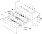
The embodiment of the application discloses full-automatic folding material loading conveyer, refer to fig. 1 and 2, including transfer gantry 1, first conveying mechanism 2, second conveying mechanism 3, folding mechanism 4, a turnover mechanism 5, locking mechanism and adjustment mechanism 8. The first conveying mechanism 2 and the second conveying mechanism 3 are both arranged on the conveying support 1. The folding mechanism 4, the turnover mechanism 5 and the locking mechanism are arranged between the first conveying mechanism 2 and the second conveying mechanism 3. The adjusting mechanism 8 is arranged on one side of the first conveying mechanism 2 far away from the second conveying mechanism 3.
The conveying support 1 comprises a support body 11 and a mounting platform 12 for mounting the first conveying mechanism 2, the second conveying mechanism 3, the folding mechanism 4, the turnover mechanism 5, the locking mechanism and the adjusting mechanism 8, two rollers 111 are arranged on two sides of the support body 11, a connecting shaft 112 is arranged between the two rollers 111, and a supporting seat 113 for supporting the connecting shaft 112 is arranged at the bottom of the support body 11.
In this embodiment, the first conveying mechanism 2 and the second conveying mechanism 3 are both common mechanisms of a conveying belt 23, and include a conveying frame 21, a conveying roller 22, a conveying belt 23 and a conveying motor, the conveying roller 22 is rotatably mounted on the conveying frame 21, the conveying belt 23 is sleeved on the outer side of the conveying roller 22, the conveying motor is fixed on the conveying frame 21, and an output shaft of the conveying motor is connected with the conveying roller 22.
In the transportation process, interior bushing pipe is earlier through second conveying mechanism 3, under second conveying mechanism 3's transport, carry out radial folding earlier through folding mechanism 4 to interior bushing pipe, pass through a folding mechanism 5 again, interior bushing pipe after folding carries out axial folding, interior bushing pipe tip locking after will folding through locking mechanism afterwards, carry towards folding mechanism 4 through first conveying mechanism 2 again, the tip of interior bushing pipe enters into in the pipeline after folding mechanism 4, the part that interior bushing pipe rear portion expandes is under folding mechanism 4 effect, fold along with the transport of interior bushing pipe, the efficiency of unreeling of pipeline has been increased by a wide margin, pipeline repair's construction cycle has been shortened.
The top of the conveying support 1 is respectively provided with a first conveying platform 11 and a second conveying platform 12, the first conveying platform 11 is arranged on one side, facing the second conveying mechanism 3, of the first conveying mechanism 2, the second conveying platform 12 is arranged on one side, facing the first conveying mechanism 2, of the second conveying mechanism 3, and an installation cavity for installing the folding mechanism 4, the folding mechanism 5 and the locking mechanism is formed between the first conveying platform 11 and the second conveying platform 12.
Referring to fig. 3 and 4, the folding mechanism 4 includes a folding bracket 41, a folding roller 42, and a driving assembly 43. The folding support 41 is installed on one side of the second conveying platform 12, the folding support 41 comprises a folding frame 411 and a plurality of folding rods 412 which are uniformly arranged along the length direction of the folding frame 411 at intervals, the driving assembly 43 is installed on the folding rods 412, the rotating shaft of the folding roller 42 is fixed on the driving assembly 43, the folding roller 42 is connected with the driving assembly 43, and the rotation and the extension of the folding roller 42 are realized.
The driving assembly 43 includes a telescopic cylinder 431 and an adjusting drive 432, and each driving assembly 43 corresponds to one folding roller 42. The driving mechanisms are symmetrically arranged on two sides of the folding bracket 41 along the length direction of the folding bracket 41, the side wall of the telescopic cylinder 431 is fixed with the folding bracket 41, and a piston rod part of the telescopic cylinder 431 is provided with a rotary through hole for an output shaft of the adjusting driving part 432 to pass through. The folding roller 42 includes a rotating roller body 421 and a rotating shaft 422 provided in the rotating roller body 421, and the rotating roller body 421 is rotatably fitted around the outside of the rotating shaft 422. The output shaft of the adjusting driver 432 is fixedly connected to the rotating shaft 422 of the folding roller 42 after passing through the rotating through hole. In this embodiment, the adjusting driving member 432 is selected as a servo motor.
When the folding conveying device is used, the distance between the folding rollers 42 positioned on the two sides of the folding support 41 is controlled through the telescopic oil cylinder 431, so that the folding rollers 42 can realize folding conveying of lining pipes with different diameters, and the application range of the conveying machine is widened.
The angle between the folding roller 42 and the folding bracket 41 is adjusted by the adjusting driving member 432, so that the angle between the folding roller 42 and the folding bracket 41 gradually increases until the angle is rotated to an obtuse angle. In this embodiment, the folding rollers 42 are symmetrically disposed on two sides of the folding bracket 41, so that the lining tube can be sequentially folded into three in the folding process, thereby reducing the probability of interference of the lining tube in the folding process.
A piston rod of the telescopic cylinder 431 is provided with a guide block 4311, the side wall of the folding rod 412 is provided with a guide groove 413 in which the guide block 4311 is embedded, the guide groove 413 horizontally penetrates through the folding rod 412, a cover plate covering the guide groove 413 is arranged at the end of the folding rod 412, and the cover plate and the folding rod 412 are welded and fixed. The guide block 4311 is embedded in the guide groove 413 and then welded and fixed with the piston rod of the telescopic cylinder 431, so that the telescopic cylinder 431 moves more stably in the operation process. In this embodiment, the guide block 4311 is disposed in a T shape, and the guide groove 413 is also disposed in a T shape, so that the folding bracket 41 can provide a supporting force for the guide block 4311 during the movement process, and the probability of falling between the telescopic cylinder 431 and the folding bracket 41 is reduced.
Referring to fig. 3, the folding mechanism 5 is disposed at one side of the folding mechanism 4, and the folding mechanism 5 includes a pressing roller 51, a pressing bracket 52, a telescopic driving member 53, an ejector plate 54, a folding plate 55, and a rotary driving member 56.
The pressing support 52 is a door-shaped support and is directly welded and fixed on the second conveying platform 12, the pressing roller 51 is rotatably mounted at the bottom of the pressing support 52, a pressing gap for passing the lining pipe is formed between the pressing roller 51 and the second conveying platform 12, and the lining pipe after being folded by the folding assembly is pressed through the pressing gap.
Referring to fig. 3 and 5, the telescopic driving member 53 is installed on the conveying support 1 and located below the second conveying platform 12, and the telescopic driving member 53 is selected as an oil cylinder. The top piston rod of the telescopic driving member 53 is fixedly connected with the ejector plate 54, the top of the ejector plate 54 is hinged to the turnover plate 55, the top of the ejector plate 54 is provided with a hinged groove 541 for hinging the turnover plate 55, the side wall of the hinged groove 541 is horizontally provided with a hinged hole 542 penetrating through the ejector plate 54, and the top of the hinged hole 542 penetrates through the ejector plate 54.
A hinge bar 551 is fixed to the flap 55, and the hinge bar 551 is placed in a hinge hole 542 formed in the knock-out plate 54. The top of the ejecting plate 54 is provided with a pressing block which presses the hinge rod 551 positioned on the folding plate 55, and the bottom of the pressing block is pressed against the hinge rod 551. The side wall of the rotation driving member 56 is fixed to the ejector plate 54, in this embodiment, the rotation driving member 56 is selected as a stepping motor, an output shaft of the stepping motor is connected to a speed reducer, the side wall of the speed reducer is fixed to the ejector plate 54, and an output end of the speed reducer is fixed to the hinge rod 551.
During the use, interior bushing pipe carries towards folding mechanism 4 under the effect of second conveying mechanism 3, after folding through folding mechanism 4, enters into and compresses tightly the clearance in, compresses tightly interior bushing pipe after folding, turns over the tip of lining pipe through turning over a mechanism 5 afterwards to the completion is rolled up after to the inside lining pipe tip.
Referring to fig. 6 and 7, a locking mechanism is provided at one side of the folding mechanism 5 for compressing and fixing the end of the lining pipe after the folding is completed. The locking mechanism comprises a pressing component 7 and a positioning component 6. The pressing component 7 and the positioning component 6 are arranged on one side of the first conveying platform 11 facing the second conveying platform 12. When the device is used, the pressing component 7 moves towards the positioning component 6, and the end part of the turned lining pipe is pressed and fixed.
The pressing assembly 7 comprises a placing support 71 arranged above the first conveying platform 11, a positioning driving piece 72 arranged at the bottom of the placing support 71, a positioning magnetic piece 73 arranged at the bottom of the positioning driving piece 72 and a locking buckle 74 mutually adsorbed with the positioning magnetic piece 73, in the embodiment, the placing support 71 is a door-shaped support, two sides of the door-shaped support are fixed with the first conveying platform 11, the positioning magnetic piece 73 is fixedly connected with the placing support 71 through an adhesive, and the locking buckle 74 is made of a magnetic material and mutually adsorbed with the positioning magnetic piece 73.
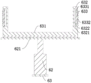
The positioning assembly 6 includes a positioning bracket 61, a positioning seat 62 and a positioning buckle 63. The positioning bracket 61 is mounted on the conveying bracket 1, a limiting magnetic sheet 621 is fixedly mounted at the top of the positioning seat 62, and the positioning buckle 63 is made of a magnetic material and is mutually adsorbed with the limiting magnetic sheet.
The positioning buckle 63 includes a positioning plate 631, a limit plate 632, a locking plate 633 and a locking ring 634, in this embodiment, the limit plate 632 is disposed on both sides of the positioning plate 631, the positioning plate 631 and the limit plate 632 are integrally disposed, and the locking ring 624 is disposed on a side wall of the positioning plate 631 and connected to a hook of the hoisting machine. A U-shaped locking groove is formed between the positioning plate 631 and the limiting plates 632 at both sides. The locking plate 633 is slidably mounted on the side of the limiting plate 632 far away from the positioning plate 631.
Referring to fig. 7 and 8, the limiting plate 632 is provided with a positioning groove 6321 for the locking plate 633 to horizontally slide, a first magnetic sheet 6322 is disposed on a side wall of the positioning groove 6321, a second magnetic sheet 6331 is disposed on a side of the locking plate 633 facing the first magnetic sheet 6322, and a magnetic pole of a face of the first magnetic sheet 6322 opposite to that of the second magnetic sheet 6331 is opposite.
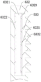
A plurality of locking protrusions 6332 are provided at intervals along the length direction of the locking plate 633 on the side of the locking plate 633 away from the stopper plate 632. In this embodiment, the positioning groove 6321 is a trapezoidal groove, the two sides of the limiting plate 632 are provided with the embedded protrusions 6323 embedded into the trapezoidal groove, during installation, the top of the positioning groove 6321 vertically penetrates through the limiting plate 632, after the locking plate 633 is inserted into the positioning groove 6321, the locking plate 633 is compressed in the positioning groove 6321 through the iron plate, and the iron plate is welded and fixed with the locking plate.
Referring to fig. 6 and 7, two sides of the locking buckle 74 are provided with a limiting groove 741 through which the locking protrusion 6332 and the pressing plate 634 pass, and after the locking protrusion 6332 and the pressing plate 634 pass through the locking buckle 74, the locking protrusion 6332 fits the top surface of the locking buckle 74, so as to achieve compression between the locking buckle 74 and the positioning buckle 63.
When the lining pipe end pressing device is used, the positioning fastener 63 extends towards the locking fastener 74 under the action of the positioning driving piece 62, so that the locking protrusion on the limiting plate 632 penetrates through the limiting groove 741 on the locking fastener 74 and then is locked with the locking fastener 74, then the lining pipe continues to move forwards under the action of the second conveying mechanism 3, at the moment, the positioning fastener 63 is separated from the limiting magnetic sheet, the locking fastener 74 is separated from the positioning magnetic sheet 73, and the pressing and fixing of the end portion of the lining pipe are completed.
Referring to fig. 1 and 9, the adjusting mechanism 8 is disposed on a side of the first conveying mechanism 2 away from the second conveying mechanism 3, and the adjusting mechanism 8 includes an adjusting bracket 81 rotatably connected to the conveying bracket 1, a fine-tuning driving member 82 for driving the adjusting bracket 81 to rotate, and a positioning roller 83 disposed at an end of the adjusting bracket 81. The fine adjustment driving member 82 is an oil cylinder, the cylinder body of the oil cylinder is hinged with the conveying bracket 1, and the output shaft of the oil cylinder is hinged with the adjusting bracket 81. The positioning roller 83 includes a roller seat 831 and a roller body 832, and the roller seat 831 is installed on a side of the adjusting bracket 81 away from the first conveying mechanism 2.
Through the stretching and retracting of the fine adjustment driving piece 82, the relative position of the side wall positioning roller 83 of the adjusting support 81 can be adjusted, so that the position of the lining pipe falling through the positioning roller 83 can be synchronously adjusted, the lining pipe can be right opposite to a pipeline inlet, and the blanking of the conveyor is more convenient.
The implementation principle of the full-automatic folding feeding conveyor of the embodiment is as follows: during the use, carry out automatic folding to interior bushing pipe through folding mechanism 4 to make interior bushing pipe do not need artifical manual folding at the in-process of carrying, shortened the artifical folding time that interior bushing pipe needed greatly, and make interior bushing pipe can fold at the in-process of carrying is automatic, and need not unreel after the completion of artificial folding again, thereby promoted lining pipe unreel efficiency at to a great extent, thereby shortened pipeline restoration construction cycle, promoted the performance of enterprises.
The embodiments of the present invention are all preferred embodiments of the present application, and the protection scope of the present application is not limited thereby, so: equivalent changes in structure, shape and principle of the present application shall be covered by the protection scope of the present application.
Claims (7)
1. The utility model provides a full-automatic folding material loading conveyer which characterized in that: the automatic folding device comprises a conveying support (1), a first conveying mechanism (2) arranged on the conveying support (1) and a folding mechanism (4) arranged on one side of the conveying mechanism, wherein the folding mechanism (4) comprises a folding support (41), folding rollers (42) arranged on the folding support (41) and a driving mechanism arranged on the folding rollers (42) and used for driving the folding rollers (42) to move, the folding rollers (42) are respectively arranged on two sides of the folding support (41), and the driving mechanism drives the folding rollers (42) to rotate;
the driving mechanism comprises telescopic oil cylinders (431) for driving the folding rollers (42) to stretch and retract and servo motors which are arranged at the end parts of the cylinders and are used for driving the folding rollers (42) to rotate, each driving mechanism corresponds to one folding roller (42), the driving mechanisms are symmetrically arranged at two sides of the folding bracket (41) along the length direction of the folding bracket (41), the telescopic oil cylinders (431) are fixedly arranged on the folding bracket (41), a piston rod part of each telescopic oil cylinder (431) is provided with a rotating through hole for an output shaft of each servo motor to pass through, and the output shaft of each servo motor is fixedly connected with the folding rollers (42) after passing through the rotating through hole;
a guide block (4311) is arranged at a piston rod of the telescopic oil cylinder (431), a guide groove (413) for embedding the guide block (4311) is formed in the side wall of the folding support (41), and the guide block (4311) is embedded into the guide groove (413) and then fixed with the piston rod of the telescopic oil cylinder (431);
the folding mechanism (4) is arranged on one side of the second conveying mechanism (3), the folding mechanism (5) is arranged on one side of the folding mechanism (4), the lining pipe after being folded by the folding mechanism (4) is turned backwards, and the overlapping part of the turned lining pipe is locked by the locking mechanism.
2. The full-automatic folding feeding conveyor according to claim 1, characterized in that: turnover mechanism (5) including set up in conveying support (1) bottom flexible driving piece (53), set up in knock-out plate (54), the rotation of telescopic driving piece (53) top install in turnover plate (55) and the drive at knock-out plate (54) top turn over flap plate (55) along knock-out plate (54) rotatory rotation driving piece (56), knock-out plate (54) set up in between first conveying mechanism (2) and second conveying mechanism (3), turn over flap plate (55) set up in the top of knock-out plate (54), the top of turning over flap plate (55) flushes with the top of first conveying platform (11).
3. The full-automatic folding feeding conveyor according to claim 2, characterized in that: the device is characterized in that a first conveying platform (11) which is flush with the top of the first conveying mechanism (2) and a second conveying platform (12) which is flush with the top of the second conveying mechanism (3) are arranged on the conveying support (1), and the ejector plate (54) is arranged between the first conveying platform (11) and the second conveying platform (12).
4. The fully automatic folding feeding conveyor according to claim 2, characterized in that: the turnover mechanism (5) further comprises a pressing roller (51) arranged on one side of the turnover plate (55) and pressing supports (52) arranged on two sides of the pressing roller (51), the pressing supports (52) are fixedly arranged on the top of the conveying support (1), the pressing roller (51) is slidably arranged on the pressing supports (52), and a positioning gap for the lining pipe to pass through is formed between the pressing roller (51) and the conveying support (1).
5. The full-automatic folding feeding conveyor according to claim 1, characterized in that: locking mechanism set up in turn over one side that second conveying mechanism (3) were kept away from in a mechanism (5), locking mechanism including set up in compress tightly subassembly (7) of first conveying mechanism (2) top and set up in locating component (6) of first conveying mechanism (2) below, compress tightly subassembly (7) including set up compress tightly support (52) on conveying support (1), set up compressing tightly the driving piece on compressing tightly support (52) and demountable installation in compressing tightly locking of driving piece bottom and detaining (74), locating component (6) are including setting up locating support (61) on conveying support (1), set up location driving piece (72) on locating support (61) and demountable installation in the location of locating driving piece (72) top detain (63), locking detain (74) with the bushing pipe compresses tightly in location knot (63).
6. The fully automatic folding feeding conveyor according to claim 5, characterized in that: location knot (63) have locating plate (631) and set up respectively in limiting plate (632) of locating plate (631) both sides and set up respectively in limiting plate (632) keep away from locking board (633) of locating plate (631) one side, set up on limiting plate (632) and supply positioning groove (6321) that locking board (633) level slided, the lateral wall of positioning groove (6321) is provided with first magnetic sheet (6322), one side that locking board (633) orientation first magnetic sheet (6322) is provided with second magnetic sheet (6331), first magnetic sheet (6322) is opposite with the relative one side magnetic pole of second magnetic sheet (6331), one side that limiting plate (632) was kept away from in locking board (633) is provided with a plurality of locking protrudingly (6332) along the length direction interval of locking board (633), the confession is seted up to both sides on locking knot (74) spacing recess (741) that locking protrudingly (6332) passed, locking protrudingly (6332) pass with locking knot (74) locking knot (741) locking behind spacing recess (741).
7. The fully automatic folding feeding conveyor according to claim 5, characterized in that: and a locking ring (634) is arranged on one side of the positioning buckle (63) facing the first conveying mechanism (2).
Priority Applications (1)
| Application Number | Priority Date | Filing Date | Title |
|---|---|---|---|
| CN202110089914.XA CN112875209B (en) | 2021-01-22 | 2021-01-22 | Full-automatic folding material loading conveyer |
Applications Claiming Priority (1)
| Application Number | Priority Date | Filing Date | Title |
|---|---|---|---|
| CN202110089914.XA CN112875209B (en) | 2021-01-22 | 2021-01-22 | Full-automatic folding material loading conveyer |
Publications (2)
| Publication Number | Publication Date |
|---|---|
| CN112875209A CN112875209A (en) | 2021-06-01 |
| CN112875209B true CN112875209B (en) | 2022-10-21 |
Family
ID=76050466
Family Applications (1)
| Application Number | Title | Priority Date | Filing Date |
|---|---|---|---|
| CN202110089914.XA Active CN112875209B (en) | 2021-01-22 | 2021-01-22 | Full-automatic folding material loading conveyer |
Country Status (1)
| Country | Link |
|---|---|
| CN (1) | CN112875209B (en) |
Families Citing this family (1)
| Publication number | Priority date | Publication date | Assignee | Title |
|---|---|---|---|---|
| CN113860083A (en) * | 2021-10-19 | 2021-12-31 | 国网山东省电力公司济南市历城区供电公司 | Electric power communication construction pay off rack |
Citations (3)
| Publication number | Priority date | Publication date | Assignee | Title |
|---|---|---|---|---|
| CN107857147A (en) * | 2017-12-08 | 2018-03-30 | 宜昌麦迪科机电设备有限责任公司 | A kind of folding discharging device |
| CN210214342U (en) * | 2019-06-10 | 2020-03-31 | 东莞华成环保包装科技股份有限公司 | Corrugated board turn-over device |
| CN212712065U (en) * | 2020-07-23 | 2021-03-16 | 青州市瑞皓塑料制品有限公司 | Folding machine is used in plastic film production with cover and press mechanism |
Family Cites Families (18)
| Publication number | Priority date | Publication date | Assignee | Title |
|---|---|---|---|---|
| GB1060863A (en) * | 1963-02-27 | 1967-03-08 | Ossakki A G | Conveying equipment |
| GB8530720D0 (en) * | 1985-12-13 | 1986-01-22 | Bio Kil Chemicals Ltd | Applying protective coating |
| GB9709503D0 (en) * | 1997-05-09 | 1997-07-02 | Poole Anthony G | Conduit lining |
| JP3773075B2 (en) * | 1997-07-03 | 2006-05-10 | 日新電機株式会社 | Sheet material processing equipment |
| JP4476853B2 (en) * | 2005-03-24 | 2010-06-09 | タキロン株式会社 | Pipe lining material folding device |
| CN201052658Y (en) * | 2006-11-24 | 2008-04-30 | 宋东辉 | Machinery and equipment for repairing old pipe by using internal lining polythene material liner tube |
| DE102008001678A1 (en) * | 2007-10-17 | 2009-04-23 | Evonik Degussa Gmbh | Use of a polyamide molding compound for lining pipes |
| JP2010149285A (en) * | 2008-12-24 | 2010-07-08 | Shonan Plastic Mfg Co Ltd | Pipe-lining material and pipe-lining method |
| CN103660277B (en) * | 2013-12-31 | 2016-05-11 | 湖南振辉管业有限公司 | A kind of internal lining pipe deformation device |
| JP5982419B2 (en) * | 2014-03-18 | 2016-08-31 | 大林道路株式会社 | Rehabilitation lining material feeding device |
| GB2527618B (en) * | 2014-10-29 | 2016-09-28 | Radius Systems Ltd | Method of lining a tubular structure |
| US9695689B2 (en) * | 2015-01-14 | 2017-07-04 | Reline America, Inc. | Mobile conveyor device for the delivery of tunnel liners |
| CN109179050A (en) * | 2018-10-08 | 2019-01-11 | 常州信息职业技术学院 | Mechanical cloth fold mechanism |
| CN109626028B (en) * | 2019-01-28 | 2020-11-03 | 安徽理工大学 | Anti-tear formula tubulose belt conveyor |
| CN110513564B (en) * | 2019-09-04 | 2021-08-24 | 重庆建工第二建设有限公司 | Ultraviolet curing lining repairing construction method |
| CN110745466B (en) * | 2019-10-25 | 2021-10-12 | 王苏莲 | Production device of hair sample plate |
| CN211942097U (en) * | 2020-01-08 | 2020-11-17 | 天津安纳赛能源科技有限公司 | Folding equipment for installing lining pipe |
| CN211599918U (en) * | 2020-01-10 | 2020-09-29 | 天津安纳赛能源科技有限公司 | Effective rotation-preventing tractive head of inside lining |
-
2021
- 2021-01-22 CN CN202110089914.XA patent/CN112875209B/en active Active
Patent Citations (3)
| Publication number | Priority date | Publication date | Assignee | Title |
|---|---|---|---|---|
| CN107857147A (en) * | 2017-12-08 | 2018-03-30 | 宜昌麦迪科机电设备有限责任公司 | A kind of folding discharging device |
| CN210214342U (en) * | 2019-06-10 | 2020-03-31 | 东莞华成环保包装科技股份有限公司 | Corrugated board turn-over device |
| CN212712065U (en) * | 2020-07-23 | 2021-03-16 | 青州市瑞皓塑料制品有限公司 | Folding machine is used in plastic film production with cover and press mechanism |
Also Published As
| Publication number | Publication date |
|---|---|
| CN112875209A (en) | 2021-06-01 |
Similar Documents
| Publication | Publication Date | Title |
|---|---|---|
| CN112875209B (en) | Full-automatic folding material loading conveyer | |
| CN207791853U (en) | A kind of conveyer belt apparatus convenient for adjusting delivery head | |
| CN111003592A (en) | Winding device for super-length soft rubber hose | |
| CN109228605B (en) | Galvanized steel sheet rubber waterstop production line and production processing technology thereof | |
| CN109159526B (en) | Efficient machining system and machining method for galvanized steel plate water stop | |
| CN112125015A (en) | HDPE geomembrane manufacturing and forming process | |
| CN214526397U (en) | Conveyor for conveying UV repair materials of pipelines | |
| CN116495536A (en) | Waterproof film non-winding core automatic winding device and waterproof film winding method | |
| KR100453373B1 (en) | A Rotary Type Looper | |
| KR20110012615A (en) | Method of manufacturing tube lining bag | |
| CN211945588U (en) | CIPP composite overturning tower | |
| CN208133311U (en) | concrete feeding device with self-locking function | |
| CN212075838U (en) | CIPP assists material feeding unit | |
| KR101110664B1 (en) | centring apparatus of tube lining bag | |
| CN220364116U (en) | Auxiliary belt feeding device controlled by hydraulic pressure | |
| CN117302698B (en) | Automobile wire harness winding equipment | |
| US3019153A (en) | Apparatus for building tires | |
| CN217144983U (en) | Lining side wall laminating equipment | |
| CN115159867B (en) | Automatic edge covering equipment for glass transportation and working method thereof | |
| CN217777862U (en) | Tire building machine template feedway and tire building machine | |
| CN117889267A (en) | Pipeline laying equipment for installing fan | |
| CN216267870U (en) | Feeding device of plastic bag sealing bag making and splitting machine | |
| CN217971179U (en) | Automatic chain driving device capable of automatically adjusting tension | |
| CN214689233U (en) | Connecting and positioning device for automobile freight | |
| CN219687369U (en) | Material conveying device for adhesive tape production |
Legal Events
| Date | Code | Title | Description |
|---|---|---|---|
| PB01 | Publication | ||
| PB01 | Publication | ||
| SE01 | Entry into force of request for substantive examination | ||
| SE01 | Entry into force of request for substantive examination | ||
| GR01 | Patent grant | ||
| GR01 | Patent grant |